EP1375273A2 - Scheibenwischvorrichtung - Google Patents
Scheibenwischvorrichtung Download PDFInfo
- Publication number
- EP1375273A2 EP1375273A2 EP03002359A EP03002359A EP1375273A2 EP 1375273 A2 EP1375273 A2 EP 1375273A2 EP 03002359 A EP03002359 A EP 03002359A EP 03002359 A EP03002359 A EP 03002359A EP 1375273 A2 EP1375273 A2 EP 1375273A2
- Authority
- EP
- European Patent Office
- Prior art keywords
- torsion spring
- spring elements
- facing
- area
- wiper device
- Prior art date
- Legal status (The legal status is an assumption and is not a legal conclusion. Google has not performed a legal analysis and makes no representation as to the accuracy of the status listed.)
- Granted
Links
Images




Classifications
-
- B—PERFORMING OPERATIONS; TRANSPORTING
- B60—VEHICLES IN GENERAL
- B60S—SERVICING, CLEANING, REPAIRING, SUPPORTING, LIFTING, OR MANOEUVRING OF VEHICLES, NOT OTHERWISE PROVIDED FOR
- B60S1/00—Cleaning of vehicles
- B60S1/02—Cleaning windscreens, windows or optical devices
- B60S1/04—Wipers or the like, e.g. scrapers
- B60S1/32—Wipers or the like, e.g. scrapers characterised by constructional features of wiper blade arms or blades
-
- B—PERFORMING OPERATIONS; TRANSPORTING
- B60—VEHICLES IN GENERAL
- B60S—SERVICING, CLEANING, REPAIRING, SUPPORTING, LIFTING, OR MANOEUVRING OF VEHICLES, NOT OTHERWISE PROVIDED FOR
- B60S1/00—Cleaning of vehicles
- B60S1/02—Cleaning windscreens, windows or optical devices
- B60S1/04—Wipers or the like, e.g. scrapers
- B60S1/32—Wipers or the like, e.g. scrapers characterised by constructional features of wiper blade arms or blades
- B60S1/34—Wiper arms; Mountings therefor
- B60S1/3425—Constructional aspects of the arm
- B60S1/3436—Mounting heads
- B60S1/344—Flat-type mounting heads
Definitions
- the invention relates to a windshield wiper device, in particular for a motor vehicle with a drive that can be driven by a drive Wiper arm that can be folded onto a window and from a window is foldable and on which a wiper blade can be arranged, wherein the wiper arm has an area facing the drive and one Has wiper blade facing area.
- Previously known windshield wiper devices have a wiper arm on, which can be folded away from the pane by means of a joint and can be folded onto the pane. So that the wiper arm in the When folded, the window should be as tight as possible against the window is pressed and thus the wiper arm in the folded away from the window Condition remains stable in this folded position, the previously known wiper arms have a tension spring.
- a disadvantage of these conventional wiper arms is that they require a certain amount of assembly work, which is the cost the windshield wiper device increased.
- the Wiper arms of the previously known windshield wiper devices the disc folded state a relatively large distance to the windshield, which is why the wiper arms have since been switched off Condition of the windshield wiper device poorly invisible can be sunk.
- the invention has for its object a windshield wiper device to improve the type mentioned in that the number the components required for the wiper arm is reduced.
- the invention solves this problem by a windshield wiper device of the type mentioned, the invention is characterized in that the area facing the drive and the area of the wiper arm facing the wiper blade is connected to two torsion spring elements, the torsion spring elements with opposite torsion angles are provided and the torsion spring elements have a rectangular cross section have a width greater than its thickness is, so that the torsion spring elements in the longitudinal direction Disc are curved towards or away from the disc. Consequently will in future be the number required for the wiper arm Components reduced to a minimum. The wiper arm will thus point in the future only the area facing the drive and the Wiper blade facing area and the two torsion spring elements on.
- the wiper arm of the windshield wiper device according to the invention can be design as a relatively flat unit, so that it is also invisible, for example in the A-pillar of a vehicle can be sunk, making the overall aesthetic Impression of the vehicle is upgraded.
- the wiper blade When the two torsion spring elements are spaced apart the wiper blade is in the folded state on the window optimally pressed against the pane and in the folded away position The condition of the wiper arm is with a maximum holding force kept away from the window.
- the two torsion spring elements can at their end regions each be connected to one another by a connecting element, so that the torsion spring elements and the connecting elements form a single spring element, reducing the number of required Components of the wiper arm and thus the assembly steps be reduced even further to its manufacture.
- a connecting element of the single spring element can be in one piece and the other connecting element in two parts.
- the two torsion spring elements with one end V-shaped be arranged on the one-piece connecting element and in each case part of the two-part connecting element on the other Be attached end of one of the torsion spring elements.
- the torsion of the torsion spring elements is pressed against each other in this design the V-shaped torsion spring elements achieved because the width of the torsion spring elements is greater than their thickness.
- the torsion spring elements naturally have the tendency towards the lowest section modulus to bend.
- the torsional spring elements have the lowest section modulus over their thickness so that they look when one pushes them against each other across their thickness, around their centerline of thickness bend what is a bending line in the longitudinal direction corresponds to the torsion spring elements.
- the two-part connecting element has fastening means, can the ends of the V-shaped torsion spring elements can be held together with little effort, after they were pressed against each other.
- torsion spring elements and / or the spring element as a stamped part or alternatively be made as a fiber reinforced plastic part.
- the connecting elements of the spring element can be in one piece, and the spring element can be used as a longitudinally bent component their torsion spring elements (41, 42) are twisted his.
- a spring element with these features can be for example in a stamping press as a stamped and bent part in one step.
- the entire wiper arm can be simply plugged together of the spring element with the drive facing Area and the area facing the wiper blade or through simply plug the torsion spring elements together with the Drive facing area and the wiper blade facing Area can be assembled quickly.
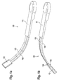
- Fig. 1 A shows a wiper arm 10 in the folded away from the window Condition, the disc is not shown here.
- the wiper arm 10 also does not point you here shown drive facing area 11 and a facing wiper blade, also not shown here Area 12 on.
- Area 12 on. are between areas 11 and 12 two spaced torsion spring elements 13.
- the torsion spring elements 13 have opposite torsion angles on so that the torsion spring elements 13 around their Longitudinal axis are twisted (see Fig. 1 C).
- the torsion spring elements 13 Opposed by the two experienced set torsion angle of the torsion spring elements 13 the torsion spring elements 13 a bending moment in their Longitudinal direction, so that the wiper arm 10 in Fig. 1 A or in Fig. 1 B receives the longitudinal bend shown.
- the opposite to each other Torsion angle of the torsion spring elements 13 and 14 against each other interchanged that is, the torsion spring element 13 shows the same torsion angle when folded away from the window on how the torsion spring element 14 in the disc folded state and vice versa (see Fig. 3 A and 3 C).
- the torsion spring elements 13 and 14 are in the areas 11 and 12 inserted. For this purpose, areas 11 and 12 Openings 15, 16, 17 and 18 on (see Fig. 1 B and 1 C). By The torsion spring elements can not be shown here in detail 13 and 14 slipping out of the areas 11 and 12 are prevented.
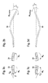
- FIG. 2A shows a spring element 20 with torsion spring elements 21 and 22 which are connected to one another by a connecting element 23. If the torsion spring elements 21 and 22 are pressed against one another by a force F (see FIG. 2 C), the torsion spring elements twist (see FIGS. 2 D, 3 A and 3 C). The torsion of the torsion spring elements 21 and 22 results from the fact that the torsion spring elements 21 and 22 have a rectangular cross section (FIG. 3A), the width of which is greater than its thickness.
- the torsion spring elements in the thickness direction have a lower section modulus than in the direction of their width, so that the force F deforms the torsion spring elements 21 and 22 from their non-twisted position, which becomes unstable when the force F is applied, into the twisted position. Due to the torsional deformation of the torsion spring elements 21 and 22, the torsion spring elements 21 and 22 experience a bending in the longitudinal direction through a force component F B acting perpendicularly on the torsion spring elements 21 and 22 (FIGS. 3 B, 3 D). If the wiper arm folded against the window (FIG. 3 B) is folded away from the window (FIG. 3 D), the torsion angles of the torsion spring elements 21 and 22 are interchanged (see FIGS.
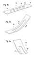
- FIG. 4 A shows a spring element 40 with two torsion spring elements 41 and 42, at their end regions by connecting elements 43 and 44 are interconnected.
- the spring element 40 can be manufactured very easily as a stamped and bent part. During the manufacturing process, the torsion spring elements 41 and 42 after punching out the spring element 40 to each other set torsion angle twisted about its longitudinal axis (Fig. 4 C) and the spring element 40 is bent along its length (Fig. 4 B).
- FIG. 5 A shows a spring element 50 with torsion spring elements 51 and 52.
- the torsion spring elements 51 and 52 are at one End region V-shaped with one another by a connecting element 53 connected.
- the torsion spring element 51 is at its other end with a connecting element part 54 and the torsion spring element 52 is a connector part at its other end 55 connected.
- the connecting element part 55 has hook elements 56, so that after pressing the torsion spring elements against each other 51 and 52 the connecting element part 54 into the connecting element part 55 can be hooked, making the through the compression of the torsion spring elements 51 and 52 created torsion of the torsion spring elements 51 and 52 and resulting longitudinal bending of the spring element 50 obtained remains (see Fig. 5 B).
- FIG. 6 A shows a spring element 60 with torsion spring elements 61 and 62, which is V-shaped at one end portion with a connecting element 63 are connected.
- the torsion spring element 61 has a connecting element part 64 at its other end region on, which is provided with a hole 65.
- the torsion spring element 62 has a connector part at its other end 66, which is connected to a hole 67.
- FIG. 7 A shows a spring element 70 with two torsion spring elements 71 and 72, which are connected by connecting elements 73 and 74 are connected.
- the connecting element 74 is used in the manufacture of the spring element 70 in its central region with a Crank 75 (Fig. 7 B) provided, whereby the V-shaped torsion spring element arranged on the connecting element 73 71 and 72 are pressed against each other so that the Torsion spring elements 71 and 72 experience torsion and that Spring element 70 is bent in its longitudinal direction (Fig. 7 B). Since the spring element 70 is inexpensively manufactured as a stamped part , it is advisable to use the offset 75 also in the Manufacture stamping tool, thereby producing the spring element 70 is significantly simplified.
Landscapes
- Engineering & Computer Science (AREA)
- Mechanical Engineering (AREA)
- Springs (AREA)
- Body Structure For Vehicles (AREA)
- Contacts (AREA)
Abstract
Description
- Fig. 1 A
- eine perspektivische Ansicht eines von der Scheibe weggeklappten Wischarmes;
- Fig. 1 B
- eine perspektivische Ansicht des Wischarmes aus Fig. 1 A im an die Scheibe angeklappten Zustand;
- Fig. 1 C
- eine perspektivische Schnittansicht durch den Wischarm aus Fig. 1 A;
- Fig. 2 A
- eine Draufsicht auf ein ausgestanztes Federelement;
- Fig. 2 B
- eine Vorderansicht auf das Federelement auf Fig. 2 A;
- Fig. 2 C
- eine Draufsicht auf das Federelement aus Fig. 2 A mit gegeneinander gedrückten Torsionsfederelementen;
- Fig. 2 D
- eine Vorderansicht des Federelementes aus Fig. 2 C;
- Fig. 3 A
- einen Querschnitt durch die Torsionsfederelemente des Federelementes aus Fig. 2 C im an die Scheibe angeklappten Zustand;
- Fig. 3 B
- einen Längsschnitt durch das Federelement aus Fig. 2 C im an die Scheibe angeklappten Zustand;
- Fig. 3 C
- einen Querschnitt durch die Torsionsfederelemente aus Fig. 2 C im von der Scheibe weggeklappten Zustand;
- Fig. 3 D
- einen Längsschnitt durch das Federelement aus Fig. 2 C im von der Scheibe weggeklappten Zustand; .
- Fig. 4 A
- eine perspektivische Ansicht auf eine zweite Ausführungsform eines Federelementes;
- Fig. 4 B
- eine perspektivische Ansicht auf das mit einer Längsbiegung versehene Federelement aus Fig. . 4 A;
- Fig. 4 C
- eine perspektivische Schnittansicht durch das in Fig. 4 B dargestellte Federelement;
- Fig. 5 A
- eine perspektivische Ansicht auf eine dritte Ausführungsform eines Federelementes;
- Fig. 5 B
- eine perspektivische Ansicht des mit einer Längsbiegung versehenen Federelementes aus 5 A;
- Fig. 6 A
- eine Draufsicht auf eine vierte Ausführungsform eines Federelementes;
- Fig. 6 B
- eine perspektivische Ansicht des längs gebogenen Federelementes aus Fig. 6 A;
- Fig. 7 A
- eine Draufsicht auf eine fünfte Ausführungsform eines Federelementes;
- Fig. 7 B
- eine perspektivische Ansicht des längs gebogenen Federelements aus Fig. 7 A.
Claims (11)
- Scheibenwischvorrichtung, insbesondere für ein Kraftfahrzeug, mit einem durch einen Antrieb antreibbaren Wischarm (10, 30), der an eine Scheibe anklappbar und von einer Scheibe wegklappbar ist und an dem ein Wischblatt anordenbar ist, wobei der Wischarm (10, 30) einen dem Antrieb zugewandten Bereich (11) und einen dem Wischblatt zugewandten Bereich (12) hat, dadurch gekennzeichnet, dass der dem Antrieb zugewandte Bereich (11) und der dem Wischblatt zugewandte Bereich (12) des Wischarms (10, 30) mit zwei Torsionsfederelementen (13, 14, 21, 22, 41, 42, 51, 52, 61, 62, 71, 72) verbunden sind, wobei die Torsionsfederelemente (13, 14, 21, 22, 41, 42, 51, 52, 61, 62, 71, 72) mit zueinander entgegen gesetzten Torsionswinkeln versehen sind und die Torsionsfederelemente (13, 14, 21, 22, 41, 42, 51, 52, 61, 62, 71, 72) einen Rechteckquerschnitt aufweisen, dessen Breite größer als seine Dicke ist, so dass die Torsionsfederelemente (13, 14, 21, 22, 41, 42, 51, 52, 61, 62, 71, 72) in Längsrichtung zur Scheibe hin gekrümmt oder von der Scheibe weg gekrümmt sind.
- Scheibenwischvorrichtung nach Anspruch 1, dadurch gekennzeichnet, dass die beiden Torsionsfederelemente (13, 14, 21, 22, 41, 42, 51, 52, 61, 62, 71, 72) voneinander beabstandet sind.
- Scheibenwischvorrichtung nach Anspruch 1 oder 2, dadurch gekennzeichnet, dass die beiden Torsionsfederelemente (13, 14, 21, 22, 41, 42, 51, 52, 61, 62, 71, 72) an ihren Endbereichen jeweils durch ein Verbindungselement (23, 43, 44, 53, 54, 55, 63, 64, 66, 73, 74) miteinander verbunden sind, so dass die Torsionsfederelemente (13, 14, 21, 22, 41, 42, 51, 52, 61, 62, 71, 72) und die Verbindungselemente (23, 43, 44, 53, 54, 55, 63, 64, 66, 73, 74) ein einziges Federelement (20, 40, 50, 60, 70) bilden.
- Scheibenwischvorrichtung nach Anspruch 3, dadurch gekennzeichnet, dass ein Verbindungselement (53, 63) einteilig und das andere Verbindungselement zweiteilig ist und die zwei Torsionsfederelemente (51, 52, 61, 62) mit ihrem einen Ende V-förmig an dem einteiligen Verbindungselement (53, 63) angeordnet sind und jeweils ein Teil (54, 55, 64, 66) des zweiteiligen Verbindungselementes am anderen Ende der Torsionsfederelemente (51, 52, 61, 62) angebracht ist.
- Scheibenwischvorrichtung nach Anspruch 4, dadurch gekennzeichnet, dass das zweiteilige Verbindungselement Befestigungsmittel (56, 68) aufweist, um die Enden der V-förmig auseinander laufenden Torsionsfederelemente (51, 52, 61, 62) zusammenzuhalten, nachdem diese gegeneinander gedrückt wurden.
- Scheibenwischvorrichtung nach einem der Ansprüche 3 bis 5, dadurch gekennzeichnet, dass ein Verbindungselement (74) in seinem Mittelbereich mit einer Kröpfung (75) versehen ist.
- Scheibenwischvorrichtung nach Anspruch 3, dadurch gekennzeichnet, dass die Verbindungselemente (43, 44) des Federelements (40) einteilig sind und das Federelement (40) als ein längsgebogenes Bauteil mit um ihre Längsachse tordierten Torsionsfederelementen (41, 42) hergestellt ist.
- Scheibenwischvorrichtung nach einem der Ansprüche 1 bis 7, dadurch gekennzeichnet, dass die Torsionsfederelemente (13, 14) und/oder das Federelement (20, 40, 50, 60, 70) als ein Stanzteil herstellbar sind.
- Scheibenwischvorrichtung nach einem der Ansprüche 1 bis 7, dadurch gekennzeichnet, dass die Torsionsfederelemente (13, 14) und/oder das Federelement (20, 40, 50, 60, 70) als ein Faser verstärktes Kunststoffteil herstellbar sind.
- Scheibenwischvorrichtung nach einem der Ansprüche 1 bis 9, dadurch gekennzeichnet, dass der dem Antrieb zugewandte Bereich (11) und der dem Wischblatt zugewandte Bereich (12) des Wischarmes (10) jeweils eine Öffnung zur Aufnahme des Federelementes (20, 40, 50, 60, 70) aufweist oder diese Bereiche (11, 12) jeweils mit zwei Öffnungen (15, 16, 17, 18) zur Aufnahme der beiden Torsionsfederelemente (13, 14) versehen sind.
- Scheibenwischvorrichtung nach Anspruch 10, dadurch gekennzeichnet, dass das Federelement (20, 40, 50, 60, 70) oder die Torsionsfederelemente (13, 14) in den Öffnungen (15, 16, 17, 18) zur Aufnahme des Federelementes (20, 40, 50, 60, 70) oder der Torsionsfederelemente (13, 14) in den dem Antrieb zugewandten Bereich (11) und/oder in den dem Wischblatt zugewandten Bereich (12) einclipsbar sind.
Applications Claiming Priority (2)
| Application Number | Priority Date | Filing Date | Title |
|---|---|---|---|
| DE10227781A DE10227781B4 (de) | 2002-06-21 | 2002-06-21 | Scheibenwischvorrichtung |
| DE10227781 | 2002-06-21 |
Publications (3)
| Publication Number | Publication Date |
|---|---|
| EP1375273A2 true EP1375273A2 (de) | 2004-01-02 |
| EP1375273A3 EP1375273A3 (de) | 2005-08-10 |
| EP1375273B1 EP1375273B1 (de) | 2008-04-23 |
Family
ID=29716583
Family Applications (1)
| Application Number | Title | Priority Date | Filing Date |
|---|---|---|---|
| EP03002359A Expired - Lifetime EP1375273B1 (de) | 2002-06-21 | 2003-02-04 | Scheibenwischvorrichtung |
Country Status (4)
| Country | Link |
|---|---|
| US (1) | US6857160B2 (de) |
| EP (1) | EP1375273B1 (de) |
| DE (2) | DE10227781B4 (de) |
| ES (1) | ES2301719T3 (de) |
Cited By (3)
| Publication number | Priority date | Publication date | Assignee | Title |
|---|---|---|---|---|
| EP1452412A1 (de) * | 2003-02-28 | 2004-09-01 | Robert Bosch Gmbh | Wischvorrichtung |
| WO2005042318A1 (de) * | 2003-09-30 | 2005-05-12 | Robert Bosch Gmbh | Wischerarm, insbesondere für eine scheibenwischvorrichtung eines kraftfahrzeugs |
| FR3126376A1 (fr) * | 2021-08-31 | 2023-03-03 | Valeo Systèmes D’Essuyage | Bras monobloc de système d’essuyage comprenant plusieurs poutres longitudinales |
Families Citing this family (29)
| Publication number | Priority date | Publication date | Assignee | Title |
|---|---|---|---|---|
| US6813802B2 (en) * | 2002-06-28 | 2004-11-09 | Valeo Electrical Systems, Inc. | Prestressed wiper arm |
| DE10341457A1 (de) * | 2003-09-09 | 2005-03-31 | Robert Bosch Gmbh | Einrichtung zum Ab- und Anklappen eines Wischarms einer Scheibenwischvorrichtung an eine Kraftfahrzeugscheibe |
| DE10361746A1 (de) * | 2003-12-29 | 2005-07-28 | Robert Bosch Gmbh | Wischereinrichtung zum Wischen einer Windschutzscheibe |
| FR2875458B1 (fr) * | 2004-09-20 | 2008-02-15 | Valeo Systemes Dessuyage | Agencement pour le montage d'un bras d'essuie-glace sur une tete d'entrainement |
| US20080263805A1 (en) * | 2007-04-26 | 2008-10-30 | Gary Sebring | Camper shell windshield wiper unit |
| USD578461S1 (en) * | 2007-09-14 | 2008-10-14 | Valeo Systemes D'essuyage | Windscreen wiper |
| FR2922842B1 (fr) * | 2007-10-30 | 2009-12-18 | Valeo Systemes Dessuyage | Dispositif d'essuyage pour surface vitree de vehicule automobile |
| USD706200S1 (en) | 2010-09-22 | 2014-06-03 | Pylon Manufacturing Corporation | Windshield wiper cover |
| US9457768B2 (en) | 2011-04-21 | 2016-10-04 | Pylon Manufacturing Corp. | Vortex damping wiper blade |
| US9174609B2 (en) | 2011-04-21 | 2015-11-03 | Pylon Manufacturing Corp. | Wiper blade with cover |
| CA2843527C (en) | 2011-07-28 | 2018-11-27 | Pylon Manufacturing Corp. | Windshield wiper adapter, connector and assembly |
| US8806700B2 (en) | 2011-07-29 | 2014-08-19 | Pylon Manufacturing Corporation | Wiper blade connector |
| WO2013019645A1 (en) | 2011-07-29 | 2013-02-07 | Pylon Manufacturing Corp. | Windshield wiper connector |
| US9108595B2 (en) | 2011-07-29 | 2015-08-18 | Pylon Manufacturing Corporation | Windshield wiper connector |
| US20130219649A1 (en) | 2012-02-24 | 2013-08-29 | Pylon Manufacturing Corp. | Wiper blade |
| MX385411B (es) | 2012-02-24 | 2025-03-18 | Pylon Mfg Corp | Escobilla limpiaparabrisas. |
| US10723322B2 (en) | 2012-02-24 | 2020-07-28 | Pylon Manufacturing Corp. | Wiper blade with cover |
| US10829092B2 (en) | 2012-09-24 | 2020-11-10 | Pylon Manufacturing Corp. | Wiper blade with modular mounting base |
| US10166951B2 (en) | 2013-03-15 | 2019-01-01 | Pylon Manufacturing Corp. | Windshield wiper connector |
| US9505380B2 (en) | 2014-03-07 | 2016-11-29 | Pylon Manufacturing Corp. | Windshield wiper connector and assembly |
| USD777079S1 (en) | 2014-10-03 | 2017-01-24 | Pylon Manufacturing Corp. | Wiper blade frame |
| USD787308S1 (en) | 2014-10-03 | 2017-05-23 | Pylon Manufacturing Corp. | Wiper blade package |
| US10363905B2 (en) | 2015-10-26 | 2019-07-30 | Pylon Manufacturing Corp. | Wiper blade |
| AU2017268008A1 (en) | 2016-05-19 | 2018-11-22 | Pylon Manufacturing Corp. | Windshield wiper connector |
| CN109311452A (zh) | 2016-05-19 | 2019-02-05 | 电缆塔制造有限公司 | 挡风玻璃雨刮器连接器 |
| EP3458315B1 (de) | 2016-05-19 | 2021-09-08 | Pylon Manufacturing Corp. | Scheibenwischerblatt |
| US11040705B2 (en) | 2016-05-19 | 2021-06-22 | Pylon Manufacturing Corp. | Windshield wiper connector |
| CN109311450A (zh) | 2016-05-19 | 2019-02-05 | 电缆塔制造有限公司 | 挡风玻璃雨刮器连接器 |
| CN116135620A (zh) * | 2021-11-17 | 2023-05-19 | 丹阳镇威汽配有限公司 | 可平衡压掣力的雨刷结构 |
Family Cites Families (8)
| Publication number | Priority date | Publication date | Assignee | Title |
|---|---|---|---|---|
| DE1806719A1 (de) * | 1968-11-02 | 1970-05-21 | Daimler Benz Ag | Scheibenwischer,insbesondere fuer Kraftfahrzeuge |
| US3670356A (en) * | 1970-03-19 | 1972-06-20 | Kashira Sakamoto | Wiper arms |
| DE3142716A1 (de) * | 1981-10-28 | 1983-05-05 | Robert Bosch Gmbh, 7000 Stuttgart | Wischvorrichtung fuer scheiben von kraftfahrzeugen |
| DE3401001A1 (de) * | 1984-01-13 | 1985-07-18 | Robert Bosch Gmbh, 7000 Stuttgart | Wischvorrichtung fuer scheiben von kraftfahrzeugen |
| GB8716422D0 (en) * | 1987-07-13 | 1987-08-19 | Stevens A | Windscreen wiper arms |
| DE19651856A1 (de) * | 1996-12-13 | 1998-06-18 | Teves Gmbh Alfred | Wischarm einer Fahrzeugscheibenwischervorrichtung |
| WO2002012033A1 (de) * | 2000-08-07 | 2002-02-14 | Valeo Auto-Electric Wischer Und Motoren Gmbh | Wischvorrichtung, insbesondere für kraftfahrzeuge |
| DE10052616A1 (de) * | 2000-10-24 | 2002-05-08 | Bosch Gmbh Robert | Wischarm |
-
2002
- 2002-06-21 DE DE10227781A patent/DE10227781B4/de not_active Expired - Fee Related
-
2003
- 2003-02-04 DE DE50309667T patent/DE50309667D1/de not_active Expired - Lifetime
- 2003-02-04 ES ES03002359T patent/ES2301719T3/es not_active Expired - Lifetime
- 2003-02-04 EP EP03002359A patent/EP1375273B1/de not_active Expired - Lifetime
- 2003-03-19 US US10/391,996 patent/US6857160B2/en not_active Expired - Fee Related
Cited By (4)
| Publication number | Priority date | Publication date | Assignee | Title |
|---|---|---|---|---|
| EP1452412A1 (de) * | 2003-02-28 | 2004-09-01 | Robert Bosch Gmbh | Wischvorrichtung |
| WO2005042318A1 (de) * | 2003-09-30 | 2005-05-12 | Robert Bosch Gmbh | Wischerarm, insbesondere für eine scheibenwischvorrichtung eines kraftfahrzeugs |
| FR3126376A1 (fr) * | 2021-08-31 | 2023-03-03 | Valeo Systèmes D’Essuyage | Bras monobloc de système d’essuyage comprenant plusieurs poutres longitudinales |
| WO2023031233A1 (fr) * | 2021-08-31 | 2023-03-09 | Valeo Systèmes d'Essuyage | Bras monobloc de système d'essuyage comprenant plusieurs poutres longitudinales |
Also Published As
| Publication number | Publication date |
|---|---|
| ES2301719T3 (es) | 2008-07-01 |
| EP1375273B1 (de) | 2008-04-23 |
| US20030233724A1 (en) | 2003-12-25 |
| DE50309667D1 (de) | 2008-06-05 |
| DE10227781B4 (de) | 2013-11-28 |
| EP1375273A3 (de) | 2005-08-10 |
| DE10227781A1 (de) | 2004-01-08 |
| US6857160B2 (en) | 2005-02-22 |
Similar Documents
| Publication | Publication Date | Title |
|---|---|---|
| EP1375273B1 (de) | Scheibenwischvorrichtung | |
| EP1363816B1 (de) | Wischarm mit einem gelenkig verbundenen wischblatt | |
| EP1979207B1 (de) | Wischarm | |
| EP1663742B1 (de) | Einrichtung zum ab- und anklappen eines wischarms einer scheibenwischvorrichtung an einer kraftfahrzeugscheibe und verfahren zum herstellen der einrichtung | |
| DE10355799A1 (de) | Wischerarm, sowie Verfahren zur Herstellung eines Wischerarms | |
| EP1575813B1 (de) | Wischebel mit einem wischarm und einem wischblatt | |
| EP1242270B1 (de) | Wischarm | |
| EP1296862A1 (de) | Wischarm für kraftfahrzeuge | |
| WO2015032563A1 (de) | Wischlippe für eine scheibenwischvorrichtung | |
| DE10329566B4 (de) | Wischarm für einen Scheibenwischer | |
| DE10043426A1 (de) | Wischvorrichtung | |
| EP1720749B1 (de) | Wischerarm für eine scheibenwischvorrichtung | |
| EP1452413B1 (de) | Wischvorrichtung | |
| DE102013222996A1 (de) | Scheibenwischvorrichtung | |
| EP1670666B1 (de) | Wischerarm, insbesondere für eine scheibenwischvorrichtung eines kraftfahrzeugs | |
| EP1278665B1 (de) | Gelenkteil für scheibenwischer | |
| WO2017178358A1 (de) | Wischarmvorrichtung | |
| DE19651856A1 (de) | Wischarm einer Fahrzeugscheibenwischervorrichtung | |
| EP1727716B1 (de) | Wischerarm für eine scheibenwischvorrichtung | |
| WO2003035439A1 (de) | Verfahren zum herstellen eines wischarms | |
| EP2107979B1 (de) | Wischarm | |
| EP2443008B1 (de) | Befestigungselement zur aufnahme eines wischerarmes | |
| DE102013217951A1 (de) | Strukturvarianten für Fin Ray-Wischer | |
| DE102004008617A1 (de) | Wischerarm für eine Scheibenwischvorrichtung | |
| DE3830031A1 (de) | Wischblatt |
Legal Events
| Date | Code | Title | Description |
|---|---|---|---|
| PUAI | Public reference made under article 153(3) epc to a published international application that has entered the european phase |
Free format text: ORIGINAL CODE: 0009012 |
|
| AK | Designated contracting states |
Kind code of ref document: A2 Designated state(s): AT BE BG CH CY CZ DE DK EE ES FI FR GB GR HU IE IT LI LU MC NL PT SE SI SK TR |
|
| AX | Request for extension of the european patent |
Extension state: AL LT LV MK RO |
|
| PUAL | Search report despatched |
Free format text: ORIGINAL CODE: 0009013 |
|
| AK | Designated contracting states |
Kind code of ref document: A3 Designated state(s): AT BE BG CH CY CZ DE DK EE ES FI FR GB GR HU IE IT LI LU MC NL PT SE SI SK TR |
|
| AX | Request for extension of the european patent |
Extension state: AL LT LV MK RO |
|
| 17P | Request for examination filed |
Effective date: 20060210 |
|
| AKX | Designation fees paid |
Designated state(s): DE ES FR GB IT |
|
| GRAP | Despatch of communication of intention to grant a patent |
Free format text: ORIGINAL CODE: EPIDOSNIGR1 |
|
| GRAS | Grant fee paid |
Free format text: ORIGINAL CODE: EPIDOSNIGR3 |
|
| GRAA | (expected) grant |
Free format text: ORIGINAL CODE: 0009210 |
|
| AK | Designated contracting states |
Kind code of ref document: B1 Designated state(s): DE ES FR GB IT |
|
| REG | Reference to a national code |
Ref country code: GB Ref legal event code: FG4D Free format text: NOT ENGLISH |
|
| REF | Corresponds to: |
Ref document number: 50309667 Country of ref document: DE Date of ref document: 20080605 Kind code of ref document: P |
|
| REG | Reference to a national code |
Ref country code: ES Ref legal event code: FG2A Ref document number: 2301719 Country of ref document: ES Kind code of ref document: T3 |
|
| ET | Fr: translation filed | ||
| PLBE | No opposition filed within time limit |
Free format text: ORIGINAL CODE: 0009261 |
|
| STAA | Information on the status of an ep patent application or granted ep patent |
Free format text: STATUS: NO OPPOSITION FILED WITHIN TIME LIMIT |
|
| 26N | No opposition filed |
Effective date: 20090126 |
|
| PGFP | Annual fee paid to national office [announced via postgrant information from national office to epo] |
Ref country code: ES Payment date: 20090225 Year of fee payment: 7 |
|
| PGFP | Annual fee paid to national office [announced via postgrant information from national office to epo] |
Ref country code: IT Payment date: 20090225 Year of fee payment: 7 |
|
| REG | Reference to a national code |
Ref country code: ES Ref legal event code: FD2A Effective date: 20110323 |
|
| PG25 | Lapsed in a contracting state [announced via postgrant information from national office to epo] |
Ref country code: IT Free format text: LAPSE BECAUSE OF NON-PAYMENT OF DUE FEES Effective date: 20100204 |
|
| PG25 | Lapsed in a contracting state [announced via postgrant information from national office to epo] |
Ref country code: ES Free format text: LAPSE BECAUSE OF NON-PAYMENT OF DUE FEES Effective date: 20110310 |
|
| PG25 | Lapsed in a contracting state [announced via postgrant information from national office to epo] |
Ref country code: ES Free format text: LAPSE BECAUSE OF NON-PAYMENT OF DUE FEES Effective date: 20100205 |
|
| PGFP | Annual fee paid to national office [announced via postgrant information from national office to epo] |
Ref country code: GB Payment date: 20130219 Year of fee payment: 11 Ref country code: FR Payment date: 20130315 Year of fee payment: 11 |
|
| GBPC | Gb: european patent ceased through non-payment of renewal fee |
Effective date: 20140204 |
|
| REG | Reference to a national code |
Ref country code: FR Ref legal event code: ST Effective date: 20141031 |
|
| PG25 | Lapsed in a contracting state [announced via postgrant information from national office to epo] |
Ref country code: GB Free format text: LAPSE BECAUSE OF NON-PAYMENT OF DUE FEES Effective date: 20140204 Ref country code: FR Free format text: LAPSE BECAUSE OF NON-PAYMENT OF DUE FEES Effective date: 20140228 |
|
| PGFP | Annual fee paid to national office [announced via postgrant information from national office to epo] |
Ref country code: DE Payment date: 20160426 Year of fee payment: 14 |
|
| REG | Reference to a national code |
Ref country code: DE Ref legal event code: R119 Ref document number: 50309667 Country of ref document: DE |
|
| PG25 | Lapsed in a contracting state [announced via postgrant information from national office to epo] |
Ref country code: DE Free format text: LAPSE BECAUSE OF NON-PAYMENT OF DUE FEES Effective date: 20170901 |