EP1375000A1 - Hammer rotor for crushing plants - Google Patents
Hammer rotor for crushing plants Download PDFInfo
- Publication number
- EP1375000A1 EP1375000A1 EP03075999A EP03075999A EP1375000A1 EP 1375000 A1 EP1375000 A1 EP 1375000A1 EP 03075999 A EP03075999 A EP 03075999A EP 03075999 A EP03075999 A EP 03075999A EP 1375000 A1 EP1375000 A1 EP 1375000A1
- Authority
- EP
- European Patent Office
- Prior art keywords
- pin
- pins
- plant
- seat
- rotor
- Prior art date
- Legal status (The legal status is an assumption and is not a legal conclusion. Google has not performed a legal analysis and makes no representation as to the accuracy of the status listed.)
- Withdrawn
Links
- 230000014759 maintenance of location Effects 0.000 claims abstract description 4
- 239000003550 marker Substances 0.000 claims 1
- 239000000463 material Substances 0.000 description 5
- CWYNVVGOOAEACU-UHFFFAOYSA-N Fe2+ Chemical compound [Fe+2] CWYNVVGOOAEACU-UHFFFAOYSA-N 0.000 description 2
- 239000007769 metal material Substances 0.000 description 2
- 230000001427 coherent effect Effects 0.000 description 1
- 230000003750 conditioning effect Effects 0.000 description 1
- 238000010276 construction Methods 0.000 description 1
- 238000012423 maintenance Methods 0.000 description 1
- 230000008018 melting Effects 0.000 description 1
- 238000002844 melting Methods 0.000 description 1
- 239000002184 metal Substances 0.000 description 1
- 239000002994 raw material Substances 0.000 description 1
- 238000011084 recovery Methods 0.000 description 1
Images

Classifications
-
- B—PERFORMING OPERATIONS; TRANSPORTING
- B02—CRUSHING, PULVERISING, OR DISINTEGRATING; PREPARATORY TREATMENT OF GRAIN FOR MILLING
- B02C—CRUSHING, PULVERISING, OR DISINTEGRATING IN GENERAL; MILLING GRAIN
- B02C13/00—Disintegrating by mills having rotary beater elements ; Hammer mills
- B02C13/02—Disintegrating by mills having rotary beater elements ; Hammer mills with horizontal rotor shaft
- B02C13/04—Disintegrating by mills having rotary beater elements ; Hammer mills with horizontal rotor shaft with beaters hinged to the rotor; Hammer mills
-
- B—PERFORMING OPERATIONS; TRANSPORTING
- B02—CRUSHING, PULVERISING, OR DISINTEGRATING; PREPARATORY TREATMENT OF GRAIN FOR MILLING
- B02C—CRUSHING, PULVERISING, OR DISINTEGRATING IN GENERAL; MILLING GRAIN
- B02C13/00—Disintegrating by mills having rotary beater elements ; Hammer mills
- B02C13/26—Details
- B02C13/28—Shape or construction of beater elements
Definitions
- This invention relates to plants for reducing loose materials into pieces of relatively small dimensions, and in particular plants for crushing ferrous and non-ferrous metal materials originating from the recovery of scrapped materials.
- Said metal materials are in the form either of parallelepipeds obtained by compacting automobile bodies, or of variously shaped pieces deriving from the sectioning of scrapped articles and requiring crushing or breaking into small pieces prior to their reuse as a source of raw material, for example prior to their melting and conditioning in blast furnaces which transform them into ingots.
- hammer crushers For crushing such materials, plants are used commonly known as hammer crushers, comprising essentially a stationary robust metal cage within which a rotor rotates at high speed.
- the material to be crushed is struck by said hammers which, either alone or in combination with one or more fixed anvils, reduce it into generally small pieces which pass through the cage apertures and are collected on the outside.
- the invention relates specifically to said hammer rotors.
- Rotors comprising a central shaft on which there are keyed generally circular parts supporting the hinge pins for the hammers, which rotate within the space between two circular parts. Said pins are supported by through cylindrical holes provided in said circular parts Hammer rotors which do not have said central shaft are also known, and are fully described in patent application RE2000A000112 in the name of the same Applicant.
- the rotors of said document essentially comprise two opposing end plates between which there are sandwiched flat profiled parts mounted on a circumferential series of parallel rods which connect said two end plates together, each individual part presenting at least one concavity within which there rotates a hammer pivoted on the rod which passes through the concavity in an axial direction.
- said rods perform two functions, one consisting of making the rotor coherent, and the other consisting of acting as the hinge pins for the hammers.
- the seats by which the rods (or pins) are engaged with the profiled parts consist of through cylindrical holes provided in these latter.
- the main object of this invention is to provide a hammer rotor on which such operations can be performed more simply, more comfortably, more rapidly and more economically.
- Another object of the invention is to attain said object within the context of a simple, rational, reliable, robust and economical construction.
- the engagement between the hammer support pins and the respective through holes provided in the flat parts of the rotor is achieved by a system by which said pins can be removed and mounted by operating in a direction generally radial to the rotor, for example by acting via the mouth through which the cage is filled.
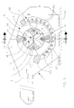
- Figure 1 is a schematic sectional side view of a crusher according to the invention.
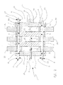
- Figure 2 is a section on the line II-II of Figure 1, showing only the rotor for simplicity.
- Figure 3 is a detail of Figure 1 on an enlarged scale, the hammer support pin being shown in its locked configuration.
- Figure 4 is a view similar to the preceding but showing the hammer in its released configuration.
- the illustrated hammer crusher is of the type without a central shaft, and forms one of the possible preferred embodiments of the plant described in the document mentioned in the introduction.
- FIGS. 1 and in particular Figure 1 show a crusher comprising an outer casing 1 in which there is installed a robust cage 2 within which a rotor 3 rotates at high speed.
- the cage 2 is formed from a series of curved side-by-side beams 20 of open ring shape, or ribs, connected together by a series of horizontal straight beams, or longitudinal members, terminating in the side walls 10 of the casing 1.
- the interrupted portions of said ribs 20 form the loading mouth of the cage through which the material to be crushed is loaded by a convenient conveyor 4.
- At least one longitudinal member 21 is more robust than the others and acts as an anvil for the hammers 30 of the rotor 3.
- the rotor 3 comprises a pair of generally circular opposing end plates 31 provided with suitable coaxial supports 35.
- the plates 31 are connected together by four rods 32 which pass through the plates 31 via respective cylindrical holes 55, and are angularly equidistant along a circumference coaxial with the supports 35.
- Profiled flat parts 33 are mounted on said rods 32, via respective cylindrical through holes 5, and are sandwiched together between the plates 31 to ensure consistency of the rotor 3.
- Each profiled part 33 presents two opposing concavities 34 which are swept by the respective hammers 30 during one complete rotation.
- Said profiled parts 33 are each joined to only two opposing rods 32, each part being rotated through 90° relative to the immediately preceding and following part.
- the rods or pins 32 have a non-circular cross-section.
- each pin 32 presents two diametrically opposing identical flats 6 of total extension.
- the holes 55 and 5 provided respectively in the end plates 31 and in the profiled parts 33 each open into the outer face of the respective member by virtue of a cut 7 disposed generally radial to the rotor 3.
- the width of said cut 7 is less than the diameter of the holes 5, 55 and pins 32, and is preferably slightly more than the distance which separates the two flats 6.
- Each pin 32 can be rotated about itself to occupy either a locked position or a released position.
- indicator means to facilitate correct orientation of the flats 6, engagement means by which the pins 32 can be rotated about themselves, and retention means for retaining the pins 32 in their locked position.
- said indicator means can consist of at least one mark associated with one end of the pin 32 and cooperating with at least one reference marking for example provided on the outer face of the plate 31.
- Said engagement means can be the actual flats 6 themselves, providing a seat for a key, or another equivalent seat, for example at least one diametrical end slot indicated by 9 at the top left in Figure 2, or at least one through diametrical end hole indicated by 99 at the bottom left in the same figure.
- these can consist for example of a profiled key as indicated schematically by 77 at the bottom right in Figure 2, and intended to be forcibly inserted into the gap between the hole 55 and the inner flat 6 of the respective pin 32.
- the illustrated embodiment is not the only one possible.
- the two diametrically opposing flats 6 could be provided only along those portions of the pins 32 passing through the profiled parts, the remaining portions being perfectly cylindrical.
- just one flat could be provided, of total extension or not, in which case one side of the cut 7 would be tangential to the respective hole 5 or 55, and the opposite side would be disposed in accordance with a secant chordal plane.
Landscapes
- Engineering & Computer Science (AREA)
- Food Science & Technology (AREA)
- Crushing And Pulverization Processes (AREA)
Abstract
Description
- This invention relates to plants for reducing loose materials into pieces of relatively small dimensions, and in particular plants for crushing ferrous and non-ferrous metal materials originating from the recovery of scrapped materials.
- Said metal materials are in the form either of parallelepipeds obtained by compacting automobile bodies, or of variously shaped pieces deriving from the sectioning of scrapped articles and requiring crushing or breaking into small pieces prior to their reuse as a source of raw material, for example prior to their melting and conditioning in blast furnaces which transform them into ingots.
- For crushing such materials, plants are used commonly known as hammer crushers, comprising essentially a stationary robust metal cage within which a rotor rotates at high speed.
- Hinged to the rotor periphery, there are a certain number of slabs, commonly known as hammers, which swing about a non-barycentric axis and are maintained facing outwards by the centrifugal forces in play.
- The material to be crushed is struck by said hammers which, either alone or in combination with one or more fixed anvils, reduce it into generally small pieces which pass through the cage apertures and are collected on the outside.
- The invention relates specifically to said hammer rotors.
- Rotors are known comprising a central shaft on which there are keyed generally circular parts supporting the hinge pins for the hammers, which rotate within the space between two circular parts. Said pins are supported by through cylindrical holes provided in said circular parts Hammer rotors which do not have said central shaft are also known, and are fully described in patent application RE2000A000112 in the name of the same Applicant.
- The rotors of said document essentially comprise two opposing end plates between which there are sandwiched flat profiled parts mounted on a circumferential series of parallel rods which connect said two end plates together, each individual part presenting at least one concavity within which there rotates a hammer pivoted on the rod which passes through the concavity in an axial direction.
- Essentially, said rods perform two functions, one consisting of making the rotor coherent, and the other consisting of acting as the hinge pins for the hammers. Again in this case, the seats by which the rods (or pins) are engaged with the profiled parts consist of through cylindrical holes provided in these latter.
- For other details regarding such rotors without a central shaft, reference should be made to the aforesaid document.
- A problem common to both the aforedescribed known types of hammer rotor lies in the fact that interventions for maintenance purposes, for example to replace the hammers and/or their pins, are particularly complex, uncomfortable, lengthy and costly.
- This derives from the fact that to replace for example even a single hammer, the end of the rotor has to be operated on, to at least partly withdraw the respective pin from its seats by sliding it parallel to itself in one direction, then in the opposite direction once the damaged hammer has been replaced.
- An idea of this operational complexity can be obtained by imagining for example a plant sited up against other equipment or against fixed structures such as brickwork.
- The main object of this invention is to provide a hammer rotor on which such operations can be performed more simply, more comfortably, more rapidly and more economically.
- Another object of the invention is to attain said object within the context of a simple, rational, reliable, robust and economical construction.
- Said objects are attained by virtue of the characteristics indicated in the claims.
- In a totally general sense, according to the invention the engagement between the hammer support pins and the respective through holes provided in the flat parts of the rotor is achieved by a system by which said pins can be removed and mounted by operating in a direction generally radial to the rotor, for example by acting via the mouth through which the cage is filled.
- By virtue of said system, described in detail hereinafter, operations of the aforesaid type are extremely simplified and facilitated, as has been proved by appropriate tests carried out on a crusher equipped with a rotor according to the invention.
- The constructional characteristics and merits of the invention will be more apparent from the ensuing reference to the figures of the accompanying drawings, which show a particular preferred embodiment thereof by way of non-limiting example.
- Figure 1 is a schematic sectional side view of a crusher according to the invention.
- Figure 2 is a section on the line II-II of Figure 1, showing only the rotor for simplicity.
- Figure 3 is a detail of Figure 1 on an enlarged scale, the hammer support pin being shown in its locked configuration.
- Figure 4 is a view similar to the preceding but showing the hammer in its released configuration.
- Firstly it should be noted that the illustrated hammer crusher is of the type without a central shaft, and forms one of the possible preferred embodiments of the plant described in the document mentioned in the introduction.
- It should also be noted that the teachings of the invention can also be applied to other types of hammer rotor, such as the hammer rotor with a central shaft mentioned in the introduction.
- Said figures, and in particular Figure 1, show a crusher comprising an outer casing 1 in which there is installed a
robust cage 2 within which arotor 3 rotates at high speed. - The
cage 2 is formed from a series of curved side-by-side beams 20 of open ring shape, or ribs, connected together by a series of horizontal straight beams, or longitudinal members, terminating in theside walls 10 of the casing 1. - The interrupted portions of said
ribs 20 form the loading mouth of the cage through which the material to be crushed is loaded by a convenient conveyor 4. - At least one
longitudinal member 21 is more robust than the others and acts as an anvil for thehammers 30 of therotor 3. - As can be seen in Figure 2, the
rotor 3 comprises a pair of generally circularopposing end plates 31 provided with suitablecoaxial supports 35. Theplates 31 are connected together by fourrods 32 which pass through theplates 31 via respectivecylindrical holes 55, and are angularly equidistant along a circumference coaxial with thesupports 35. - Profiled
flat parts 33 are mounted on saidrods 32, via respective cylindrical through holes 5, and are sandwiched together between theplates 31 to ensure consistency of therotor 3. - Each profiled
part 33 presents twoopposing concavities 34 which are swept by therespective hammers 30 during one complete rotation. - Said profiled
parts 33 are each joined to only twoopposing rods 32, each part being rotated through 90° relative to the immediately preceding and following part. - In that manner those portions of the
rods 32 which face theconcavities 34 act as swing pins for thehammers 30. - As shown also in Figures 3 and 4, the rods or
pins 32 have a non-circular cross-section. - Specifically, each
pin 32 presents two diametrically opposingidentical flats 6 of total extension. - The
holes 55 and 5 provided respectively in theend plates 31 and in the profiledparts 33 each open into the outer face of the respective member by virtue of acut 7 disposed generally radial to therotor 3. - The width of said
cut 7 is less than the diameter of theholes 5, 55 andpins 32, and is preferably slightly more than the distance which separates the twoflats 6. - Each
pin 32 can be rotated about itself to occupy either a locked position or a released position. - In Figures 3 and 4, said rotation is of 90°. When in said locked position the distance between the
flats 6 lies parallel to thecut 7, whereas when in the released position said distance lies transversely to the extension of thecut 7. - When the
pin 32 has been released it can be separated from therotor 3 together with itsown hammers 30, extracted from thecage 2 through its loading mouth, inspected and overhauled, and finally remounted by operating in the reverse manner. - There are also provided indicator means to facilitate correct orientation of the
flats 6, engagement means by which thepins 32 can be rotated about themselves, and retention means for retaining thepins 32 in their locked position. - For example said indicator means, not shown for simplicity, can consist of at least one mark associated with one end of the
pin 32 and cooperating with at least one reference marking for example provided on the outer face of theplate 31. - Said engagement means can be the
actual flats 6 themselves, providing a seat for a key, or another equivalent seat, for example at least one diametrical end slot indicated by 9 at the top left in Figure 2, or at least one through diametrical end hole indicated by 99 at the bottom left in the same figure. - With regard to said retention means, these can consist for example of a profiled key as indicated schematically by 77 at the bottom right in Figure 2, and intended to be forcibly inserted into the gap between the
hole 55 and theinner flat 6 of therespective pin 32. - The merits and advantages of the invention, as well as its operation, are apparent from the aforegoing and from an examination of the accompanying figures.
- The illustrated embodiment is not the only one possible. For example, the two diametrically opposing
flats 6 could be provided only along those portions of thepins 32 passing through the profiled parts, the remaining portions being perfectly cylindrical. - As a variant, just one flat could be provided, of total extension or not, in which case one side of the
cut 7 would be tangential to therespective hole 5 or 55, and the opposite side would be disposed in accordance with a secant chordal plane.
Claims (6)
- A crushing plant comprising a cage (21) within which there rotates at high speed a generally cylindrical rotor (3), on the periphery of which there are provided longitudinal hinge pins (32) for crushing hammers (30), characterised in that the retention seats (5; 55) for said pins each open into the outer surface of the rotor via a respective generally radial cut (7) having, at least in proximity to its connection to said seat, a width less than the pin diameter, said pins presenting, at least in correspondence with those portions contained in said seat, a non-circular cross-section, one transverse dimension of which is slightly less than said width, said pins being arranged to rotate within their seats between a first angular position or locked position, and a second angular position or released position, in which said one transverse dimension of said non-circular cross-section lies substantially parallel to and respectively generally oblique to said cut.
- A plant as claimed in claim 1, characterised in that said non-circular cross-section is achieved by at least one flat.
- A plant as claimed in claim 2, characterised in that said at least one flat extends for the entire length of the pin.
- A plant as claimed in claim 1, characterised by comprising means for retaining the pin in its locked position, such as at least one key intended to be forcibly inserted into the gap defined between the pin seat and said at least one flat.
- A plant as claimed in claim 1, characterised by comprising means for rotating the pin about itself, such as at least one key seat provided at one end of the pin.
- A plant as claimed in claim 1, characterised by comprising means for indicating at least the locked position of the pin, such as a mark applied to the end of the pin and at least one reference marker associated with the respective seat.
Applications Claiming Priority (2)
| Application Number | Priority Date | Filing Date | Title |
|---|---|---|---|
| IT2002RE000051A ITRE20020051A1 (en) | 2002-06-18 | 2002-06-18 | HAMMER ROTOR FOR CRUSHING PLANTS |
| ITRE20020051 | 2002-06-18 |
Publications (1)
| Publication Number | Publication Date |
|---|---|
| EP1375000A1 true EP1375000A1 (en) | 2004-01-02 |
Family
ID=11454248
Family Applications (1)
| Application Number | Title | Priority Date | Filing Date |
|---|---|---|---|
| EP03075999A Withdrawn EP1375000A1 (en) | 2002-06-18 | 2003-04-04 | Hammer rotor for crushing plants |
Country Status (2)
| Country | Link |
|---|---|
| EP (1) | EP1375000A1 (en) |
| IT (1) | ITRE20020051A1 (en) |
Cited By (3)
| Publication number | Priority date | Publication date | Assignee | Title |
|---|---|---|---|---|
| EP2277626A3 (en) * | 2009-07-22 | 2011-05-11 | Jenz GmbH Maschinen- und Fahrzeugbau | Rotor for a comminution machine |
| RU2481893C1 (en) * | 2011-09-13 | 2013-05-20 | Федеральное государственное бюджетное образовательное учреждение высшего профессионального образования "Воронежский государственный аграрный университет имени императора Петра I" (ФГБОУ ВПО Воронежский ГАУ) | Grinder of loose materials |
| DE102017105283A1 (en) | 2017-03-13 | 2018-09-13 | Jenz Gmbh Maschinen- Und Fahrzeugbau | Tools for a crusher |
Citations (4)
| Publication number | Priority date | Publication date | Assignee | Title |
|---|---|---|---|---|
| DE662128C (en) * | 1937-10-30 | 1938-07-05 | Schuechtermann & Kremer Baum A | Hammer mill |
| DE3317070C1 (en) * | 1983-05-10 | 1984-07-26 | Maschinenfabrik B.Maier GmbH & Co KG, 4800 Bielefeld | Hammer mill |
| DE3744241A1 (en) * | 1987-12-24 | 1989-07-06 | Lindemann Maschfab Gmbh | Fastening method for wear elements |
| DE20000905U1 (en) * | 2000-01-20 | 2000-04-06 | RK Rose + Krieger GmbH & Co. KG Verbindungs- und Positioniersysteme, 32423 Minden | Pipe connector |
-
2002
- 2002-06-18 IT IT2002RE000051A patent/ITRE20020051A1/en unknown
-
2003
- 2003-04-04 EP EP03075999A patent/EP1375000A1/en not_active Withdrawn
Patent Citations (4)
| Publication number | Priority date | Publication date | Assignee | Title |
|---|---|---|---|---|
| DE662128C (en) * | 1937-10-30 | 1938-07-05 | Schuechtermann & Kremer Baum A | Hammer mill |
| DE3317070C1 (en) * | 1983-05-10 | 1984-07-26 | Maschinenfabrik B.Maier GmbH & Co KG, 4800 Bielefeld | Hammer mill |
| DE3744241A1 (en) * | 1987-12-24 | 1989-07-06 | Lindemann Maschfab Gmbh | Fastening method for wear elements |
| DE20000905U1 (en) * | 2000-01-20 | 2000-04-06 | RK Rose + Krieger GmbH & Co. KG Verbindungs- und Positioniersysteme, 32423 Minden | Pipe connector |
Cited By (3)
| Publication number | Priority date | Publication date | Assignee | Title |
|---|---|---|---|---|
| EP2277626A3 (en) * | 2009-07-22 | 2011-05-11 | Jenz GmbH Maschinen- und Fahrzeugbau | Rotor for a comminution machine |
| RU2481893C1 (en) * | 2011-09-13 | 2013-05-20 | Федеральное государственное бюджетное образовательное учреждение высшего профессионального образования "Воронежский государственный аграрный университет имени императора Петра I" (ФГБОУ ВПО Воронежский ГАУ) | Grinder of loose materials |
| DE102017105283A1 (en) | 2017-03-13 | 2018-09-13 | Jenz Gmbh Maschinen- Und Fahrzeugbau | Tools for a crusher |
Also Published As
| Publication number | Publication date |
|---|---|
| ITRE20020051A0 (en) | 2002-06-18 |
| ITRE20020051A1 (en) | 2003-12-18 |
Similar Documents
| Publication | Publication Date | Title |
|---|---|---|
| EP2458096B1 (en) | Ground crushing and screening device for a bucket, a fixed screen or other, and relative bucket or fixed screen | |
| US7726597B2 (en) | Vertical shaft impactor rock crusher | |
| EP1809422B2 (en) | Mineral breaker | |
| US7658343B2 (en) | Drum construction for a mineral breaker | |
| BR112012006755B1 (en) | Mill lining element | |
| US7753302B2 (en) | Rotor for an impact crusher | |
| US20060118671A1 (en) | Tire size reduction/wire separation system | |
| EP1375000A1 (en) | Hammer rotor for crushing plants | |
| KR100599459B1 (en) | crusher | |
| EP3184174A1 (en) | Gyration-type crusher | |
| US4919344A (en) | Grinding mill apparatus | |
| US2738932A (en) | Preliminary disintegrating machine particularly adapted to size reduce wood blocks, rubber tires and the like | |
| US20070138034A1 (en) | Plunger can assembly | |
| EP2319624B1 (en) | Method for fine crushing of lump material | |
| Shah | Construction, working and maintenance of crushers for crushing bulk materials | |
| EP3932559B1 (en) | Hydraulic crusher concave retaining system | |
| KR200351072Y1 (en) | Crushing device | |
| EP1907122B1 (en) | Rubble grinder | |
| CN208757701U (en) | Vertical sludge crusher | |
| EP3184173A1 (en) | Gyration-type crusher | |
| JP2003334462A (en) | Roll crusher | |
| EP1205249B1 (en) | Hammer rotor for crushing plant | |
| KR102445962B1 (en) | Crushing drum for wood crusher | |
| CN105583025B (en) | Cut burnt roller | |
| CN213557299U (en) | Rotor structure for tooth-type screening crusher |
Legal Events
| Date | Code | Title | Description |
|---|---|---|---|
| PUAI | Public reference made under article 153(3) epc to a published international application that has entered the european phase |
Free format text: ORIGINAL CODE: 0009012 |
|
| AK | Designated contracting states |
Kind code of ref document: A1 Designated state(s): AT BE BG CH CY CZ DE DK EE ES FI FR GB GR HU IE IT LI LU MC NL PT RO SE SI SK TR |
|
| AX | Request for extension of the european patent |
Extension state: AL LT LV MK |
|
| 17P | Request for examination filed |
Effective date: 20040526 |
|
| AKX | Designation fees paid |
Designated state(s): AT BE BG CH CY CZ DE DK EE ES FI FR GB GR HU IE IT LI LU MC NL PT RO SE SI SK TR |
|
| AXX | Extension fees paid |
Extension state: MK Payment date: 20040526 Extension state: LV Payment date: 20040526 Extension state: LT Payment date: 20040526 Extension state: AL Payment date: 20040526 |
|
| GRAP | Despatch of communication of intention to grant a patent |
Free format text: ORIGINAL CODE: EPIDOSNIGR1 |
|
| STAA | Information on the status of an ep patent application or granted ep patent |
Free format text: STATUS: THE APPLICATION IS DEEMED TO BE WITHDRAWN |
|
| 18D | Application deemed to be withdrawn |
Effective date: 20100129 |