EP1373646B1 - Mehrzweckbaufahrzeug des schaufellader-typs - Google Patents
Mehrzweckbaufahrzeug des schaufellader-typs Download PDFInfo
- Publication number
- EP1373646B1 EP1373646B1 EP02722353A EP02722353A EP1373646B1 EP 1373646 B1 EP1373646 B1 EP 1373646B1 EP 02722353 A EP02722353 A EP 02722353A EP 02722353 A EP02722353 A EP 02722353A EP 1373646 B1 EP1373646 B1 EP 1373646B1
- Authority
- EP
- European Patent Office
- Prior art keywords
- assembly
- loader
- directional control
- shovel
- control valves
- Prior art date
- Legal status (The legal status is an assumption and is not a legal conclusion. Google has not performed a legal analysis and makes no representation as to the accuracy of the status listed.)
- Expired - Lifetime
Links
- 238000010276 construction Methods 0.000 title claims abstract 5
- 239000012530 fluid Substances 0.000 claims abstract description 8
- 230000000712 assembly Effects 0.000 claims abstract description 4
- 238000000429 assembly Methods 0.000 claims abstract description 4
- 238000009826 distribution Methods 0.000 claims abstract description 4
- 238000012384 transportation and delivery Methods 0.000 claims abstract 2
- 239000000470 constituent Substances 0.000 claims description 4
- 238000006073 displacement reaction Methods 0.000 description 3
- 239000003381 stabilizer Substances 0.000 description 3
- 230000000750 progressive effect Effects 0.000 description 2
- 235000003434 Sesamum indicum Nutrition 0.000 description 1
- 244000000231 Sesamum indicum Species 0.000 description 1
- 241001080024 Telles Species 0.000 description 1
- 230000005540 biological transmission Effects 0.000 description 1
- 238000013016 damping Methods 0.000 description 1
- 238000010586 diagram Methods 0.000 description 1
- 238000012423 maintenance Methods 0.000 description 1
- 238000004519 manufacturing process Methods 0.000 description 1
- 239000000463 material Substances 0.000 description 1
- 238000000034 method Methods 0.000 description 1
- 238000003860 storage Methods 0.000 description 1
Images


Classifications
-
- E—FIXED CONSTRUCTIONS
- E02—HYDRAULIC ENGINEERING; FOUNDATIONS; SOIL SHIFTING
- E02F—DREDGING; SOIL-SHIFTING
- E02F9/00—Component parts of dredgers or soil-shifting machines, not restricted to one of the kinds covered by groups E02F3/00 - E02F7/00
- E02F9/20—Drives; Control devices
- E02F9/22—Hydraulic or pneumatic drives
- E02F9/2278—Hydraulic circuits
- E02F9/2296—Systems with a variable displacement pump
-
- E—FIXED CONSTRUCTIONS
- E02—HYDRAULIC ENGINEERING; FOUNDATIONS; SOIL SHIFTING
- E02F—DREDGING; SOIL-SHIFTING
- E02F3/00—Dredgers; Soil-shifting machines
- E02F3/04—Dredgers; Soil-shifting machines mechanically-driven
- E02F3/96—Dredgers; Soil-shifting machines mechanically-driven with arrangements for alternate or simultaneous use of different digging elements
- E02F3/963—Arrangements on backhoes for alternate use of different tools
- E02F3/964—Arrangements on backhoes for alternate use of different tools of several tools mounted on one machine
-
- E—FIXED CONSTRUCTIONS
- E02—HYDRAULIC ENGINEERING; FOUNDATIONS; SOIL SHIFTING
- E02F—DREDGING; SOIL-SHIFTING
- E02F9/00—Component parts of dredgers or soil-shifting machines, not restricted to one of the kinds covered by groups E02F3/00 - E02F7/00
- E02F9/08—Superstructures; Supports for superstructures
- E02F9/0858—Arrangement of component parts installed on superstructures not otherwise provided for, e.g. electric components, fenders, air-conditioning units
- E02F9/0875—Arrangement of valve arrangements on superstructures
-
- E—FIXED CONSTRUCTIONS
- E02—HYDRAULIC ENGINEERING; FOUNDATIONS; SOIL SHIFTING
- E02F—DREDGING; SOIL-SHIFTING
- E02F9/00—Component parts of dredgers or soil-shifting machines, not restricted to one of the kinds covered by groups E02F3/00 - E02F7/00
- E02F9/20—Drives; Control devices
- E02F9/2004—Control mechanisms, e.g. control levers
Definitions
- the present invention relates to the field of public works machinery, and more particularly to earth-moving machines that can work indifferently as loader as a backhoe, machines which in the following description, will be designated by the expression " loader / backhoe. "
- This frame supports in its central part a driving and control station.
- a loader assembly At the front of the chassis is a loader assembly and, at the rear, an excavator assembly.
- each work tool has its own control means for feeding the hydraulic cylinders actuating the constituent elements of each work tool.
- Each control cylinder can therefore be controlled selectively via a hydraulic distributor operable by a manipulator, manipulator which can be either a mechanical control lever and linkage, or a hydraulic control or an electrical control.
- the document US 5,471,908 describes a machine of the loader / excavator type, the hydraulic circuit comprises a distributor dedicated to the configuration of the loader assembly, and a second distributor dedicated to the displacement of the excavator assembly, hydraulically interconnected by a priority valve.
- the distributors controlling the loader assembly there are at least two in number, one for controlling the parallel arms articulated by articulated relative to the frame and supporting the bucket and a second distributor controlling the orientation of the bucket relative to the arms and the frame.
- an additional command may act on the configuration of the bucket, usually called 4 in 1 command.
- control valves of the charger assembly are therefore grouped on the chassis, and this substantially at the level of the driving members.
- the distributors supplying the power of the control cylinders are grouped on a separate module mounted at the rear of the chassis.
- the operator rotates his seat for the one hand, set up the lateral stabilizers, and secondly, actuate the control means of the cylinders allowing the implementation of the shovel.
- Such a shovel assembly thus implies, in order to ensure its operation, the presence of at least six distributors, namely two for the control of the lateral stabilizers that the machine comprises, one for the control of the boom, one for the control of the arm articulated on said boom, one for the control of the articulated bucket at the end of the arm, and the last for the control of the rotation of the boom.
- the first problem to be solved by the invention thus concerns the production of a multi-purpose machine comprising a hydraulic control system for the tools of the machine of simplified design, easy to set up and of great reliability during its operation. use.
- Such a circuit also makes it possible to have priority steering control.
- the invention also aims to arrange the elementary distributors so that the controls for performing the excavator function are central, while those to fulfill the loader function are distributed on both sides of the aforementioned elements.
- the distributors supplying the cylinders that comprises the shovel assembly are manually controlled (but could also be hydraulically controlled) and the distributors of the jacks of the loader assembly are, in turn, hydraulically controlled .
- the distributors of the loader assembly are arranged laterally with respect to those of the excavator assembly, thus making it possible to facilitate the hydraulic connection with said loader assembly which is situated at the front of the machine.
- the invention therefore relates to a public works vehicle loader / backhoe type.
- This machine essentially comprises a frame, designated by the general reference (1), supported by two axles (2,3), the front axle (2) being provided with steering wheels and drive (4) and the rear axle of driving wheels (5) of large diameter.
- a heat engine which drives a gearbox with converter connected by transmission to the two front and rear axles and the hydraulic circuit for controlling the work equipment also mounted on said frame.
- Said work equipment is, on the one hand, constituted by a loader type assembly designated by the general reference (6), mounted at the front of said frame and, on the other hand, by a "backhoe” type assembly or “Excavator”, designated by the general reference (7) mounted meanwhile at the rear of the frame.
- the charger assembly (6) comprises two arms (8) articulated at (9) on the chassis and arranged on either side of the cover (10). These arms (8) can be moved under the action of two arm cylinders (11) also laterally on the frame (12), and whose rod acts on the intermediate portion (13) of the side arms. (8) .
- a bucket (9) associated with rods (14,15) forming a deformable parallelogram.
- the inclination of the bucket (9) is obtained via a jack (16).
- the bucket (9) may optionally be constituted by an assembly comprising two distinct elements offset relative to one another, and allowing to adopt several configurations that allow it to fulfill, in addition to the loader function, that of blade of a bulldozer, or pliers, or an opening dump.
- the shovel assembly (7) is, in turn, mounted at the rear of the frame on a rigid transverse frame (20) set back from the drive wheels (5).
- This excavator is conventional and consists essentially of an arrow (23) associated with an arm (24) at the end of which is mounted a bucket (25).
- the boom (23) receives a rotational movement about a vertical axis relative to the frame. Furthermore, the boom (23) is hinged relative to the frame, the arm (24) being articulated relative to the end of said boom (23) and the bucket (25) relative to the end of the arm (24).
- two lateral stabilizers are also mounted on the frame.
- the driving position and control of the machine is mounted on the central part of the chassis.
- This control station thus comprises conventional driving means and manipulators, preferably of the hydraulic type, to ensure the selection of the distributors controlling the various cylinders of the charger assembly.
- This driving position is designed so that by simply pivoting the seat, we can use the backhoe set arranged at the rear.
- the excavator assembly is controlled by six distributors operable by individual manual controls.
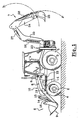
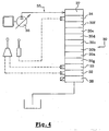
- all the distributors supplying the control cylinders of both the loader and the excavator are grouped in the form of a module (30) as shown in Figures 3 and 4.
- This block or module (30) is mounted on a transverse beam (31) integral with the two longitudinal members constituting the frame, and this through damping assemblies for recovering the stresses experienced by said frame during work operations.
- valve block (30) comprises six mechanically controlled distributors (30a to 30f) intended to carry out the controls of the excavator which are located at the rear of the machine.
- a seventh distributor (38g) is also expected to originate in the event that the machine is likely to receive additional options.
- the distributors (32,33,34) intended to feed the cylinders of the loader assembly are arranged laterally with respect to those of the shovel assembly thus facilitating the mechanical connection with the loader controls which are located at the front of the machine.
- This circuit (35) is associated with a priority valve (37) on the direction function.
- each of the distributors is carried out at a shared rate.
- an electro-distributor (38) for the immobilization cylinders of the shovel is also associated with the block (30) of distributors.
- control of the distributors is mixed, namely mechanical and hydraulic, these controls could also be performed in a fully hydraulic manner.
- the solution according to the invention has many advantages among which we can mention ease of assembly, maintenance, account because all functions are integrated into a single block.
Landscapes
- Engineering & Computer Science (AREA)
- Mining & Mineral Resources (AREA)
- Civil Engineering (AREA)
- General Engineering & Computer Science (AREA)
- Structural Engineering (AREA)
- Mechanical Engineering (AREA)
- Operation Control Of Excavators (AREA)
- Transition And Organic Metals Composition Catalysts For Addition Polymerization (AREA)
- Shovels (AREA)
Claims (3)
- Mehrzweckbaufahrzeug vom Schaufellader/Radlader-Typ mit einem fahrbaren Fahrwerk, in dessen mittlerem Abschnitt ein Fahr- und Steuerstand angeordnet ist, wobei das Fahrwerk an seiner Vorderseite mit einer Radladeranordnung versehen ist und an seiner Rückseite mit einer Schaufelbagger- oder Löffelbaggeranordnung versehen ist, die unabhängig voneinander betätigbar sind mittels eines hydraulischen Kreises, der in selektiver Weise eine Vielzahl von Verteilern versorgt, die mittels Steuerschalter betätigbar sind, welche Hydraulikzylinder steuern, die Bestandteile der Radladeranordnung sowie der Schaufelbagger- oder Löffelbaggeranordnung sind,
dadurch gekennzeichnet, dass:die Gesamtheit der Verteiler, die diese Hydraulikzylinder versorgen, in Form einer einzigen Baugruppe (30) zusammengefasst und in Querrichtung in das Fahrwerk eingebaut sind und zwar zwischen der Hinterachse und dem Rahmen für die Schaufelbagger-oder Löffelbaggeranordnung;die Versorgung mit dem Hydraulikfluid mittels einer Pumpe (36) mit variabler Leistung erfolgt, die ein Hauptventil (37) für die Lenkung speist, das der aus den Verteilern bestehenden Baugruppe (30) zugeordnet ist;der Zufluss des Fluids zu jedem Verteiler mittels eines Leistungsreglers erfolgt, der die Durchflussmenge für jede Tranche steuert. - Baufahrzeug nach Anspruch 1, dadurch gekennzeichnet, dass die Verteiler, die die Zylinder für die Baggeranordnung (7) speisen, manuell oder hydraulisch ansteuerbar sind und dass die Verteiler für die Zylinder der Ladeanordnung (6) hydraulisch ansteuerbar sind.
- Baufahrzeug nach einem der Ansprüche 1 und 2, dadurch gekennzeichnet, dass die Verteiler (32, 33 34) für die Ladeanordnung seitlich bezüglich denjenigen für die Baggeranordnung angeordnet sind.
Applications Claiming Priority (3)
| Application Number | Priority Date | Filing Date | Title |
|---|---|---|---|
| FR0104278 | 2001-03-29 | ||
| FR0104278A FR2822859B1 (fr) | 2001-03-29 | 2001-03-29 | Engin de travaux publics polyvalent du type chargeuse- pelleteuse |
| PCT/FR2002/000974 WO2002079581A1 (fr) | 2001-03-29 | 2002-03-20 | Engin de travaux publics polyvalent du type chargeuse-pelleteuse |
Publications (2)
| Publication Number | Publication Date |
|---|---|
| EP1373646A1 EP1373646A1 (de) | 2004-01-02 |
| EP1373646B1 true EP1373646B1 (de) | 2007-09-26 |
Family
ID=8861712
Family Applications (1)
| Application Number | Title | Priority Date | Filing Date |
|---|---|---|---|
| EP02722353A Expired - Lifetime EP1373646B1 (de) | 2001-03-29 | 2002-03-20 | Mehrzweckbaufahrzeug des schaufellader-typs |
Country Status (6)
| Country | Link |
|---|---|
| US (1) | US20040060712A1 (de) |
| EP (1) | EP1373646B1 (de) |
| AT (1) | ATE374288T1 (de) |
| DE (1) | DE60222642D1 (de) |
| FR (1) | FR2822859B1 (de) |
| WO (1) | WO2002079581A1 (de) |
Families Citing this family (10)
| Publication number | Priority date | Publication date | Assignee | Title |
|---|---|---|---|---|
| WO2005095258A1 (ja) * | 2004-03-30 | 2005-10-13 | Hitachi Construction Machinery Co., Ltd. | 作業機械 |
| US7434653B2 (en) * | 2005-03-31 | 2008-10-14 | Caterpillar Inc. | On-demand electro-hydraulic steering system |
| US20070131466A1 (en) * | 2005-12-12 | 2007-06-14 | Gutzwiller Timothy M | Work machine with electrical and hydraulic service centers |
| US20070246288A1 (en) * | 2006-04-24 | 2007-10-25 | Mather Daniel T | Dual force hydraulic steering system for articulated work machine |
| CN104564919A (zh) * | 2015-01-27 | 2015-04-29 | 第一拖拉机股份有限公司 | 一种轮式拖拉机液压系统 |
| JP6570440B2 (ja) * | 2015-12-14 | 2019-09-04 | 株式会社クボタ | 作業車 |
| US10480156B2 (en) * | 2015-12-14 | 2019-11-19 | Kubota Corporation | Work vehicle |
| CN107059979A (zh) * | 2017-04-12 | 2017-08-18 | 管中林 | 一种具有多种功能的步履挖掘机 |
| CN107059978A (zh) * | 2017-04-12 | 2017-08-18 | 管中林 | 一种具有稳定互联悬架的步履挖掘机 |
| CN119843730B (zh) * | 2025-02-18 | 2025-10-17 | 山东威猛工程机械有限公司 | 一种两头忙及其整体式车架 |
Family Cites Families (17)
| Publication number | Priority date | Publication date | Assignee | Title |
|---|---|---|---|---|
| US2979081A (en) * | 1959-08-17 | 1961-04-11 | Deere & Co | Control mechanism |
| US3302317A (en) * | 1963-09-26 | 1967-02-07 | Domres Franklin | Grader |
| US3329225A (en) * | 1964-12-09 | 1967-07-04 | Thomas J Dunn | Vehicle with selectively changeable work implements |
| FR1483942A (fr) * | 1966-04-28 | 1967-06-09 | Poclain Sa | Nouvel engin pour travaux de terrassement |
| US3627155A (en) * | 1970-04-09 | 1971-12-14 | Deere & Co | Hydraulic fluid hose handling means for a side shiftable backhoe |
| US3752337A (en) * | 1971-08-20 | 1973-08-14 | Reynolds Tobacco Co R | Device for handling bagged or bundled soft material |
| US4051860A (en) * | 1975-12-15 | 1977-10-04 | Massey-Ferguson Inc. | Valve control mechanism |
| US4479349A (en) * | 1981-11-19 | 1984-10-30 | General Signal Corporation | Hydraulic control system |
| GB2183795B (en) * | 1985-12-03 | 1989-10-04 | Kubota Ltd | Valve control structure for working vehicle |
| US5138756A (en) * | 1989-12-08 | 1992-08-18 | Ford New Holland, Inc. | Method of converting backhoe controls |
| US5471908A (en) * | 1994-02-16 | 1995-12-05 | Case Corporation | Hydraulic system for backhoe |
| US5553992A (en) * | 1994-10-24 | 1996-09-10 | New Holland North America, Inc. | Controls for a skid steer loader |
| US6018895A (en) * | 1996-03-28 | 2000-02-01 | Clark Equipment Company | Valve stack in a mini-excavator directing fluid under pressure from multiple pumps to actuable elements |
| AU720849B2 (en) * | 1996-03-28 | 2000-06-15 | Clark Equipment Company | Multifunction valve stack |
| JP3070918B2 (ja) * | 1998-07-15 | 2000-07-31 | 株式会社小松製作所 | ブルドーザ |
| US6640409B2 (en) * | 2001-09-25 | 2003-11-04 | Case Corporation | Method for retrofitting a swing damping valve circuit to a work vehicle |
| US6843004B2 (en) * | 2003-01-15 | 2005-01-18 | Robert G. Loeb | Heavy equipment safety device |
-
2001
- 2001-03-29 FR FR0104278A patent/FR2822859B1/fr not_active Expired - Fee Related
-
2002
- 2002-03-20 AT AT02722353T patent/ATE374288T1/de not_active IP Right Cessation
- 2002-03-20 DE DE60222642T patent/DE60222642D1/de not_active Expired - Lifetime
- 2002-03-20 EP EP02722353A patent/EP1373646B1/de not_active Expired - Lifetime
- 2002-03-20 WO PCT/FR2002/000974 patent/WO2002079581A1/fr not_active Ceased
-
2003
- 2003-09-19 US US10/666,882 patent/US20040060712A1/en not_active Abandoned
Also Published As
| Publication number | Publication date |
|---|---|
| FR2822859B1 (fr) | 2003-07-18 |
| WO2002079581A1 (fr) | 2002-10-10 |
| ATE374288T1 (de) | 2007-10-15 |
| DE60222642D1 (de) | 2007-11-08 |
| FR2822859A1 (fr) | 2002-10-04 |
| EP1373646A1 (de) | 2004-01-02 |
| US20040060712A1 (en) | 2004-04-01 |
Similar Documents
| Publication | Publication Date | Title |
|---|---|---|
| EP1373646B1 (de) | Mehrzweckbaufahrzeug des schaufellader-typs | |
| EP0863264B1 (de) | Schaufelbagger mit teleskopischem Arm | |
| EP0046234B1 (de) | Material- und Bodenbewegungsfahrzeug | |
| FR2615219A1 (fr) | Vehicule a pelle retrocaveuse | |
| FR2635130A1 (de) | ||
| FR2493820A1 (fr) | Grue autotractee equipee de supports deployables commandes hydrauliquement et electriquement, et mecanisme de verrouillage associe auxdits supports | |
| FR2694604A1 (fr) | Structure de circuit hydraulique pour une rétropelle. | |
| FR2993904A1 (fr) | Chargeur frontal | |
| FR2558500A1 (fr) | Engin de travaux publics polyvalent | |
| FR2622936A1 (fr) | Circuit hydraulique pour une pelle retrocaveuse | |
| FR2762053A1 (fr) | Configuration de vanne et dispositif de montage | |
| EP0528005A1 (de) | Multifunktionsbaumaschine | |
| FR2532671A1 (fr) | Chargeur-excavateur a un seul equipement de travail | |
| FR2810351A1 (fr) | Engin chargeur et de travaux publics, perfectionne | |
| FR2675831A1 (fr) | Engin de travaux publics comportant une tourelle. | |
| EP0391808A1 (de) | Teleskopische Hebevorrichtung für ein Fahrzeug, insbesondere für einen Lader | |
| EP1245739B1 (de) | Baumaschine | |
| FR2526746A1 (fr) | Vehicule comportant des roues sustentatrices supplementaires | |
| FR2727998A1 (fr) | Engin de travaux publics de type chargeur, dont la cabine de pilotage ainsi que l'equipement de travail sont montes sur une tourelle | |
| FR2569216A1 (fr) | Dispositif pour le curage, en particulier de saignees perpendiculaires a une voie routiere | |
| FR2552050A1 (fr) | Ensemble propulseur a helice de bateau | |
| FR2869195A1 (fr) | Machine pour effectuer des travaux de fauchage/ debroussaillage et d'elagage | |
| WO2005059258A1 (fr) | Engin de travaux publics | |
| FR2847281A1 (fr) | Engin de chantier tel que pelleteuse ou excavatrice | |
| EP1679282B1 (de) | Kran mit ausgeglichenem Hauptausleger und Hilfsausleger, der senkrecht gehalten werden kann |
Legal Events
| Date | Code | Title | Description |
|---|---|---|---|
| PUAI | Public reference made under article 153(3) epc to a published international application that has entered the european phase |
Free format text: ORIGINAL CODE: 0009012 |
|
| 17P | Request for examination filed |
Effective date: 20030909 |
|
| AK | Designated contracting states |
Kind code of ref document: A1 Designated state(s): AT BE CH CY DE DK ES FI FR GB GR IE IT LI LU MC NL PT SE TR |
|
| AX | Request for extension of the european patent |
Extension state: AL LT LV MK RO SI |
|
| GRAP | Despatch of communication of intention to grant a patent |
Free format text: ORIGINAL CODE: EPIDOSNIGR1 |
|
| GRAS | Grant fee paid |
Free format text: ORIGINAL CODE: EPIDOSNIGR3 |
|
| GRAA | (expected) grant |
Free format text: ORIGINAL CODE: 0009210 |
|
| AK | Designated contracting states |
Kind code of ref document: B1 Designated state(s): AT BE CH CY DE DK ES FI FR GB GR IE IT LI LU MC NL PT SE TR |
|
| REG | Reference to a national code |
Ref country code: GB Ref legal event code: FG4D Free format text: NOT ENGLISH |
|
| REG | Reference to a national code |
Ref country code: CH Ref legal event code: EP |
|
| GBT | Gb: translation of ep patent filed (gb section 77(6)(a)/1977) |
Effective date: 20071001 |
|
| REF | Corresponds to: |
Ref document number: 60222642 Country of ref document: DE Date of ref document: 20071108 Kind code of ref document: P |
|
| REG | Reference to a national code |
Ref country code: IE Ref legal event code: FG4D Free format text: LANGUAGE OF EP DOCUMENT: FRENCH |
|
| RAP2 | Party data changed (patent owner data changed or rights of a patent transferred) |
Owner name: VOLVO CONSTRUCTION EQUIPMENT AB |
|
| NLT2 | Nl: modifications (of names), taken from the european patent patent bulletin |
Owner name: VOLVO CONSTRUCTION EQUIPMENT AB Effective date: 20071121 |
|
| PG25 | Lapsed in a contracting state [announced via postgrant information from national office to epo] |
Ref country code: FI Free format text: LAPSE BECAUSE OF FAILURE TO SUBMIT A TRANSLATION OF THE DESCRIPTION OR TO PAY THE FEE WITHIN THE PRESCRIBED TIME-LIMIT Effective date: 20070926 |
|
| PG25 | Lapsed in a contracting state [announced via postgrant information from national office to epo] |
Ref country code: AT Free format text: LAPSE BECAUSE OF FAILURE TO SUBMIT A TRANSLATION OF THE DESCRIPTION OR TO PAY THE FEE WITHIN THE PRESCRIBED TIME-LIMIT Effective date: 20070926 |
|
| NLV1 | Nl: lapsed or annulled due to failure to fulfill the requirements of art. 29p and 29m of the patents act | ||
| PG25 | Lapsed in a contracting state [announced via postgrant information from national office to epo] |
Ref country code: NL Free format text: LAPSE BECAUSE OF FAILURE TO SUBMIT A TRANSLATION OF THE DESCRIPTION OR TO PAY THE FEE WITHIN THE PRESCRIBED TIME-LIMIT Effective date: 20070926 Ref country code: GR Free format text: LAPSE BECAUSE OF FAILURE TO SUBMIT A TRANSLATION OF THE DESCRIPTION OR TO PAY THE FEE WITHIN THE PRESCRIBED TIME-LIMIT Effective date: 20071227 Ref country code: ES Free format text: LAPSE BECAUSE OF FAILURE TO SUBMIT A TRANSLATION OF THE DESCRIPTION OR TO PAY THE FEE WITHIN THE PRESCRIBED TIME-LIMIT Effective date: 20080106 |
|
| REG | Reference to a national code |
Ref country code: IE Ref legal event code: FD4D |
|
| PG25 | Lapsed in a contracting state [announced via postgrant information from national office to epo] |
Ref country code: PT Free format text: LAPSE BECAUSE OF FAILURE TO SUBMIT A TRANSLATION OF THE DESCRIPTION OR TO PAY THE FEE WITHIN THE PRESCRIBED TIME-LIMIT Effective date: 20080226 |
|
| PG25 | Lapsed in a contracting state [announced via postgrant information from national office to epo] |
Ref country code: SE Free format text: LAPSE BECAUSE OF FAILURE TO SUBMIT A TRANSLATION OF THE DESCRIPTION OR TO PAY THE FEE WITHIN THE PRESCRIBED TIME-LIMIT Effective date: 20071226 |
|
| PG25 | Lapsed in a contracting state [announced via postgrant information from national office to epo] |
Ref country code: DE Free format text: LAPSE BECAUSE OF FAILURE TO SUBMIT A TRANSLATION OF THE DESCRIPTION OR TO PAY THE FEE WITHIN THE PRESCRIBED TIME-LIMIT Effective date: 20071228 Ref country code: DK Free format text: LAPSE BECAUSE OF FAILURE TO SUBMIT A TRANSLATION OF THE DESCRIPTION OR TO PAY THE FEE WITHIN THE PRESCRIBED TIME-LIMIT Effective date: 20070926 |
|
| PLBE | No opposition filed within time limit |
Free format text: ORIGINAL CODE: 0009261 |
|
| STAA | Information on the status of an ep patent application or granted ep patent |
Free format text: STATUS: NO OPPOSITION FILED WITHIN TIME LIMIT |
|
| 26N | No opposition filed |
Effective date: 20080627 |
|
| BERE | Be: lapsed |
Owner name: VOLVO CONSTRUCTION EQUIPMENT HOLDING SWEDEN A.B. Effective date: 20080331 |
|
| PG25 | Lapsed in a contracting state [announced via postgrant information from national office to epo] |
Ref country code: MC Free format text: LAPSE BECAUSE OF NON-PAYMENT OF DUE FEES Effective date: 20080331 Ref country code: IE Free format text: LAPSE BECAUSE OF FAILURE TO SUBMIT A TRANSLATION OF THE DESCRIPTION OR TO PAY THE FEE WITHIN THE PRESCRIBED TIME-LIMIT Effective date: 20070926 |
|
| REG | Reference to a national code |
Ref country code: CH Ref legal event code: PL |
|
| PG25 | Lapsed in a contracting state [announced via postgrant information from national office to epo] |
Ref country code: CH Free format text: LAPSE BECAUSE OF NON-PAYMENT OF DUE FEES Effective date: 20080331 Ref country code: LI Free format text: LAPSE BECAUSE OF NON-PAYMENT OF DUE FEES Effective date: 20080331 |
|
| PG25 | Lapsed in a contracting state [announced via postgrant information from national office to epo] |
Ref country code: BE Free format text: LAPSE BECAUSE OF NON-PAYMENT OF DUE FEES Effective date: 20080331 |
|
| PG25 | Lapsed in a contracting state [announced via postgrant information from national office to epo] |
Ref country code: CY Free format text: LAPSE BECAUSE OF FAILURE TO SUBMIT A TRANSLATION OF THE DESCRIPTION OR TO PAY THE FEE WITHIN THE PRESCRIBED TIME-LIMIT Effective date: 20070926 |
|
| PG25 | Lapsed in a contracting state [announced via postgrant information from national office to epo] |
Ref country code: LU Free format text: LAPSE BECAUSE OF NON-PAYMENT OF DUE FEES Effective date: 20080320 |
|
| PG25 | Lapsed in a contracting state [announced via postgrant information from national office to epo] |
Ref country code: TR Free format text: LAPSE BECAUSE OF FAILURE TO SUBMIT A TRANSLATION OF THE DESCRIPTION OR TO PAY THE FEE WITHIN THE PRESCRIBED TIME-LIMIT Effective date: 20070926 |
|
| REG | Reference to a national code |
Ref country code: FR Ref legal event code: PLFP Year of fee payment: 15 |
|
| PGFP | Annual fee paid to national office [announced via postgrant information from national office to epo] |
Ref country code: FR Payment date: 20160329 Year of fee payment: 15 Ref country code: GB Payment date: 20160318 Year of fee payment: 15 |
|
| PGFP | Annual fee paid to national office [announced via postgrant information from national office to epo] |
Ref country code: IT Payment date: 20160317 Year of fee payment: 15 |
|
| GBPC | Gb: european patent ceased through non-payment of renewal fee |
Effective date: 20170320 |
|
| REG | Reference to a national code |
Ref country code: FR Ref legal event code: ST Effective date: 20171130 |
|
| PG25 | Lapsed in a contracting state [announced via postgrant information from national office to epo] |
Ref country code: FR Free format text: LAPSE BECAUSE OF NON-PAYMENT OF DUE FEES Effective date: 20170331 |
|
| PG25 | Lapsed in a contracting state [announced via postgrant information from national office to epo] |
Ref country code: GB Free format text: LAPSE BECAUSE OF NON-PAYMENT OF DUE FEES Effective date: 20170320 Ref country code: IT Free format text: LAPSE BECAUSE OF NON-PAYMENT OF DUE FEES Effective date: 20170320 |