EP1372359A1 - Circuit d'alimentation pour plusieurs chaínes de DEL - Google Patents
Circuit d'alimentation pour plusieurs chaínes de DEL Download PDFInfo
- Publication number
- EP1372359A1 EP1372359A1 EP03011739A EP03011739A EP1372359A1 EP 1372359 A1 EP1372359 A1 EP 1372359A1 EP 03011739 A EP03011739 A EP 03011739A EP 03011739 A EP03011739 A EP 03011739A EP 1372359 A1 EP1372359 A1 EP 1372359A1
- Authority
- EP
- European Patent Office
- Prior art keywords
- led
- control circuit
- strand
- current flowing
- led strand
- Prior art date
- Legal status (The legal status is an assumption and is not a legal conclusion. Google has not performed a legal analysis and makes no representation as to the accuracy of the status listed.)
- Granted
Links
Images


Classifications
-
- H—ELECTRICITY
- H05—ELECTRIC TECHNIQUES NOT OTHERWISE PROVIDED FOR
- H05B—ELECTRIC HEATING; ELECTRIC LIGHT SOURCES NOT OTHERWISE PROVIDED FOR; CIRCUIT ARRANGEMENTS FOR ELECTRIC LIGHT SOURCES, IN GENERAL
- H05B45/00—Circuit arrangements for operating light-emitting diodes [LED]
- H05B45/30—Driver circuits
- H05B45/37—Converter circuits
- H05B45/3725—Switched mode power supply [SMPS]
- H05B45/375—Switched mode power supply [SMPS] using buck topology
-
- H—ELECTRICITY
- H05—ELECTRIC TECHNIQUES NOT OTHERWISE PROVIDED FOR
- H05B—ELECTRIC HEATING; ELECTRIC LIGHT SOURCES NOT OTHERWISE PROVIDED FOR; CIRCUIT ARRANGEMENTS FOR ELECTRIC LIGHT SOURCES, IN GENERAL
- H05B45/00—Circuit arrangements for operating light-emitting diodes [LED]
- H05B45/30—Driver circuits
- H05B45/37—Converter circuits
- H05B45/3725—Switched mode power supply [SMPS]
- H05B45/38—Switched mode power supply [SMPS] using boost topology
-
- H—ELECTRICITY
- H05—ELECTRIC TECHNIQUES NOT OTHERWISE PROVIDED FOR
- H05B—ELECTRIC HEATING; ELECTRIC LIGHT SOURCES NOT OTHERWISE PROVIDED FOR; CIRCUIT ARRANGEMENTS FOR ELECTRIC LIGHT SOURCES, IN GENERAL
- H05B45/00—Circuit arrangements for operating light-emitting diodes [LED]
- H05B45/30—Driver circuits
- H05B45/37—Converter circuits
- H05B45/3725—Switched mode power supply [SMPS]
- H05B45/385—Switched mode power supply [SMPS] using flyback topology
Definitions
- the present invention relates to a control circuit for at least one LED strand, whereby a switch is arranged in series with each LED strand and each LED strand has one Has supply connection, via which it can be connected to a supply voltage, wherein each switch can be controlled such that a current flow in the associated LED string is made possible with a first control circuit, which is designed to switch the minimum to control an LED string in such a way that an adjustable mean value of the LED strand flowing through current is achieved.
- FIG. 1 shows such a control circuit in which, for example, an LED string is formed by four LEDs D1 to D4.
- a switch T1 is arranged on one side of the LED string and is connected on the one hand to a control circuit and on the other hand to a supply voltage U V.
- the LED string is connected to ground via a shunt resistor R Sh .
- the voltage drop across the resistor R Sh Sh voltage U is applied to an integrator 10 which provides at its output a size corresponding to the mean value i LED corresponds to the current i LED flowing through the LED string.
- a comparator 12 provides at its output a control voltage U control ready to be supplied to a further comparator fourteenth Its second input is supplied with the triangular voltage U D provided by a triangular generator 16. Its output is connected to the control input of switch T1.
- i LED target can be the average i LEDs of the current through the LED string vary and thus change the brightness of the light emitted by LEDs D1 to D4, ie dim.
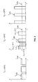
- This control circuit has several disadvantages: for example, when operating such an LED string in a motor vehicle, it must be expected that the supply voltage U V , for example the on-board voltage, is not constant.
- the coordination of the number of LEDs in the LED string must therefore be selected so that even with a minimal supply voltage U V, a sufficiently high current can be achieved through the LED string to ensure a certain minimum brightness of the LEDs. If the entire supply voltage is now always applied to the LED strand in order to achieve a high degree of efficiency, an increase in the supply voltage leads to an increase in the peak current flowing through the LED strand, see the thinly drawn curves in the middle illustration in FIG. 2.
- LEDs have a negative temperature coefficient of several millivolts per degree Celsius.
- FIG. 2 shows the peak current ⁇ LED at various temperatures as an example in thick lines.
- i LED is set, the peak current ⁇ LED varies considerably.
- the LED string is triggered in a pulsed manner, with the pauses between two successive pulses being larger at higher temperatures.
- the wavelength of the light emitted by the LEDs in turn changes undesirably.
- the switching element a series resistor upstream.
- the energy converted in the series resistor leads to an additional increase of the ambient temperature and thus reinforces the negative effect.
- the object of the present invention is therefore to provide a control circuit for the type mentioned at the outset in such a way that even when the supply voltage changes and the ambient temperature an operation of the LED string to deliver Guaranteed light in the desired brightness and color with high efficiency can be.
- the first-mentioned object is achieved by a control circuit with the features of Claim 1.
- the second object is achieved by a method with the Features of claim 14.
- the invention is based on the knowledge that the above objects can be achieved in an ideal manner if the peak value ⁇ LED of the current flowing through the LED strand is determined and the supply voltage provided to the LED strand is regulated in a corresponding manner.
- the mean i LED of the current flowing through the LED strand is regulated, the brightness of the light emitted by the LEDs is kept constant and adjustable.
- the color of the light emitted by the LED strand is kept adjustable and adjustable. If the supply voltage that is provided for the LED string is then designed so that as little energy as possible is converted into heat, a particularly high degree of efficiency can be achieved. This also enables LED strings to be implemented with any number of LEDs, ie when the peak current is specified, it does not matter whether the control circuit is used to operate an LED strand with 5 or 10 LEDs.
- the at least one LED strand is preferably operated in a clocked manner, the mean value of the current flowing through the at least one LED strand, in particular by pulse width modulation is set.
- the eye takes over the function of the integrator. As long as the LEDs are always operated with the same peak current, changes only the brightness of the light emitted by the LEDs, but not its color.
- the second control loop is preferred in view of a particularly high efficiency designed, the supply voltage of the string voltage of the at least one LED string adapt.
- the first and second control loops are designed Determine actual values for mean and peak value only for a first LED string wherein at least a second LED strand corresponds to that for the first LED strand determined actual values is operated.
- This measure can be made up of several LED arrays of existing LED arrays while achieving the advantages according to the invention control, but the two control loops are only executed once.
- the first control loop can have a first comparator with which the actual value of the Average value of the current flowing through the at least one LED strand with a specifiable one Setpoint value is compared, with the output signal of the first comparator on the input of a second comparator is coupled, the second input of which is connected to a Triangle signal is applied, the output signal of the second comparator to the at least one switch is coupled.
- the second control loop can have a third comparator with which the actual value of the Peak value of the current flowing through the at least one LED strand with a predeterminable one Setpoint value is compared, with the output signal of the third comparator on the first input of a fourth comparator is coupled, the second input of a triangular signal is applied, the output signal of the fourth comparator is coupled to a voltage converter.
- the average of the minimum a current flowing through an LED strand can be changed by an operator.
- the wavelength of the emitted by the LED strand Light the peak value of the current flowing through the at least one LED strand be designed to be changeable by an operator.
- the second control loop comprises a peak value detector for the current flowing through the at least one LED strand, a peak value can be predetermined for the current flowing through the at least one LED strand and the second control loop is designed to provide a supply voltage so that the predeterminable peak value is achieved. This results in an optimal adaptation of the supply voltage U V to the LED string voltage U St.
- the second control circuit preferably comprises a DC / DC converter, the output voltage of which is coupled to the at least one supply connection.
- the DC / DC converter is preferred in particular as a step-up converter, step-down converter or flyback converter.
- An inductance is preferably arranged in series with the output of the second control circuit.
- FIG. 3 shows a control circuit according to the invention, the circuit component in the right half of FIG. 3 essentially corresponding to the control circuit shown in FIG. 1.
- the drop across the resistor R Sh Sh voltage U is supplied to a peak detector 18 whose output signal is correlated with the actual peak value I LEDact and a comparator is supplied stirred 20th
- the adjustable peak value ⁇ LED setpoint is present at the other input of the comparator 20.
- One of the difference between ⁇ ⁇ LEDact LEDnom and corresponding voltage U Rule2 is supplied to a further comparator 22 whose other input is driven with a triangular voltage U D2.
- the output signal of the comparator 22 is present at the control input of a switch T2, which is connected to the supply voltage U V.
- a diode D is arranged in the reverse direction between the output of the switch T2 and ground.
- An inductance L is arranged in series between the output of the switch T2 and the supply voltage connection of the switch T1.
- the T1-side connection of inductance L is connected to ground via a capacitor C.
- the voltage U A provided by the capacitor C is preferably selected such that it is essentially equal to the phase voltage U St.
- a step-down converter is realized in the present case by the comparator 22, the switch T2 and the diode D and the triangular generator 21, which provides the voltage U D2 .
- the comparator 22 the switch T2 and the diode D and the triangular generator 21, which provides the voltage U D2 .
- other types of converters in particular DC / DC converters, can also be present at this point in the circuit, depending on the application.
- the oscillator frequency of the triangle generator 16 should preferably be chosen to be substantially lower than the oscillator frequency of the triangle generator 21.
- the integrator 10 can be differently outlined, that is, differently than by an RC element , be realized.
- the peak value detector 18 can be implemented differently than by a diode-capacitor combination.
Landscapes
- Circuit Arrangement For Electric Light Sources In General (AREA)
- Led Devices (AREA)
- Braiding, Manufacturing Of Bobbin-Net Or Lace, And Manufacturing Of Nets By Knotting (AREA)
Applications Claiming Priority (2)
| Application Number | Priority Date | Filing Date | Title |
|---|---|---|---|
| DE10225670A DE10225670A1 (de) | 2002-06-10 | 2002-06-10 | Ansteuerschaltung für mindestens einen LED-Strang |
| DE10225670 | 2002-06-10 |
Publications (2)
| Publication Number | Publication Date |
|---|---|
| EP1372359A1 true EP1372359A1 (fr) | 2003-12-17 |
| EP1372359B1 EP1372359B1 (fr) | 2007-02-21 |
Family
ID=29557718
Family Applications (1)
| Application Number | Title | Priority Date | Filing Date |
|---|---|---|---|
| EP03011739A Expired - Lifetime EP1372359B1 (fr) | 2002-06-10 | 2003-05-23 | Circuit d'alimentation pour plusieurs chaînes de DEL |
Country Status (6)
| Country | Link |
|---|---|
| US (1) | US7061394B2 (fr) |
| EP (1) | EP1372359B1 (fr) |
| CN (1) | CN100469208C (fr) |
| AT (1) | ATE354930T1 (fr) |
| CA (1) | CA2431514A1 (fr) |
| DE (2) | DE10225670A1 (fr) |
Cited By (5)
| Publication number | Priority date | Publication date | Assignee | Title |
|---|---|---|---|---|
| EP1871144A1 (fr) * | 2006-06-22 | 2007-12-26 | Patent-Treuhand-Gesellschaft für elektrische Glühlampen mbH | Dispositif d'excitation de diodes électroluminescentes et procédé correspondant |
| WO2014049216A1 (fr) * | 2012-09-28 | 2014-04-03 | Renault S.A.S. | Procédé d'élaboration d'une consigne de fonctionnement pour un ensemble de diodes d'éclairage d'un projecteur de véhicule, et véhicule correspondant |
| EP2420107B1 (fr) | 2009-04-14 | 2015-07-08 | Tridonic GmbH & Co KG | Régulation de la puissance de del, à l'aide de la moyenne du courant des del et d'un compteur bidirectionnel |
| WO2016173776A1 (fr) * | 2015-04-30 | 2016-11-03 | Osram Gmbh | Ensemble formant circuit et procédé de réduction de la modulation de lumière d'au moins une source de lumière commandée par une tension |
| AT519021A5 (de) * | 2009-04-14 | 2018-03-15 | Tridonic Gmbh & Co Kg | Leistungsregelung von led, mittels mittelwert des led-stroms und bidirektionaler zähler |
Families Citing this family (29)
| Publication number | Priority date | Publication date | Assignee | Title |
|---|---|---|---|---|
| US6836157B2 (en) * | 2003-05-09 | 2004-12-28 | Semtech Corporation | Method and apparatus for driving LEDs |
| DE102004003698B4 (de) * | 2004-01-24 | 2005-11-24 | Preh Gmbh | Schaltungsanordnung zur Ansteuerung von Leuchtmitteln |
| US7824627B2 (en) | 2004-02-03 | 2010-11-02 | S.C. Johnson & Son, Inc. | Active material and light emitting device |
| US7202608B2 (en) * | 2004-06-30 | 2007-04-10 | Tir Systems Ltd. | Switched constant current driving and control circuit |
| JP4646110B2 (ja) * | 2004-10-22 | 2011-03-09 | 株式会社中川研究所 | 半導体発光素子用電源および照明装置 |
| US7492108B2 (en) * | 2005-08-11 | 2009-02-17 | Texas Instruments Incorporated | System and method for driving light-emitting diodes (LEDs) |
| GB2440603B (en) * | 2005-09-12 | 2008-11-12 | Lee Alan Bourgeois | A shunt that allows a vehicle with pulsed lamp checking to use light emitting diodes |
| WO2007041574A1 (fr) | 2005-10-03 | 2007-04-12 | S. C. Johnson & Son, Inc. | Appareil lumineux |
| TWI433588B (zh) | 2005-12-13 | 2014-04-01 | Koninkl Philips Electronics Nv | 發光二極體發光裝置 |
| WO2007088505A1 (fr) | 2006-01-31 | 2007-08-09 | Koninklijke Philips Electronics N.V. | Circuit d'attaque de del |
| US7456586B2 (en) * | 2006-01-31 | 2008-11-25 | Jabil Circuit, Inc. | Voltage controlled light source and image presentation device using the same |
| US7307391B2 (en) * | 2006-02-09 | 2007-12-11 | Led Smart Inc. | LED lighting system |
| US8063581B2 (en) * | 2006-06-22 | 2011-11-22 | Koninklijke Philips Electronics N.V. | Drive circuit for driving a load with pulsed current |
| US7705547B2 (en) * | 2006-10-19 | 2010-04-27 | Honeywell International Inc. | High-side current sense hysteretic LED controller |
| DE102006059355A1 (de) * | 2006-12-15 | 2008-06-19 | Robert Bosch Gmbh | Ansteuerungseinrichtung und Verfahren zum Betrieb wenigstens einer Reihenschaltung von Leuchtdioden |
| US7898187B1 (en) * | 2007-02-08 | 2011-03-01 | National Semiconductor Corporation | Circuit and method for average-current regulation of light emitting diodes |
| CN101106852B (zh) * | 2007-06-25 | 2010-12-08 | 四川大学 | 照明发光二极管阵列的恒流和调光控制电路 |
| US20090115343A1 (en) * | 2007-11-06 | 2009-05-07 | Brian Matthew King | LED Power Regulator with High-Speed LED Switching |
| WO2009136318A1 (fr) | 2008-05-06 | 2009-11-12 | Koninklijke Philips Electronics N.V. | Unité de pilotage de del |
| IT1391326B1 (it) * | 2008-07-21 | 2011-12-05 | Mt Lights S R L | "alimentatore elettronico di potenza di diodi led" |
| US8350498B2 (en) * | 2010-04-28 | 2013-01-08 | National Semiconductor Corporation | Dynamic current equalization for light emitting diode (LED) and other applications |
| CN102387627B (zh) | 2010-09-03 | 2015-07-29 | 奥斯兰姆有限公司 | 发光二极管驱动及调光的方法和装置、以及照明系统 |
| US8395331B2 (en) * | 2010-10-05 | 2013-03-12 | Semtech Corporation | Automatic dropout prevention in LED drivers |
| CN102055324A (zh) * | 2011-01-11 | 2011-05-11 | 北方工业大学 | 采用积分电路的电源控制装置及方法 |
| DE202012100109U1 (de) | 2012-01-12 | 2012-02-27 | Productivity Engineering Gesellschaft für Prozessintegration mbH | Schaltungsanordnung zum Betreiben von LED-Lichtquellen |
| FR2996403B1 (fr) * | 2012-09-28 | 2015-05-22 | Renault Sa | Procede de regulation de la tension aux bornes d'un ensemble de diodes d'eclairage d'un projecteur de vehicule, et vehicule correspondant |
| DE102012224346A1 (de) * | 2012-12-21 | 2014-06-26 | Osram Gmbh | Schaltungsanordnung zum Betreiben von n parallel geschalteten Strängen mit mindestens einer Halbleiterlichtquelle |
| CN103199506B (zh) * | 2013-04-12 | 2015-07-15 | 深圳市华星光电技术有限公司 | 光源驱动模组的过流保护电路及背光模组 |
| DE102022200429A1 (de) | 2022-01-17 | 2023-07-20 | Osram Gmbh | Zweistufiges betriebsgerät mit isolierbarem getakteten konverter als leistungsfaktorkorrektor und regelungsverfahren für das betriebsgerät |
Citations (2)
| Publication number | Priority date | Publication date | Assignee | Title |
|---|---|---|---|---|
| US4090189A (en) * | 1976-05-20 | 1978-05-16 | General Electric Company | Brightness control circuit for LED displays |
| DE19950135A1 (de) * | 1999-10-18 | 2001-04-19 | Patent Treuhand Ges Fuer Elektrische Gluehlampen Mbh | Ansteuerschaltung für LED und zugehöriges Betriebsverfahren |
Family Cites Families (7)
| Publication number | Priority date | Publication date | Assignee | Title |
|---|---|---|---|---|
| US5147294A (en) * | 1990-10-01 | 1992-09-15 | Trustees Of Boston University | Therapeutic method for reducing chronic pain in a living subject |
| US5758644A (en) * | 1995-06-07 | 1998-06-02 | Masimo Corporation | Manual and automatic probe calibration |
| US5949225A (en) * | 1998-03-19 | 1999-09-07 | Astec International Limited | Adjustable feedback circuit for adaptive opto drives |
| JP2001326569A (ja) * | 2000-05-16 | 2001-11-22 | Toshiba Corp | Led駆動回路及び光送信モジュール |
| JP2002203988A (ja) * | 2000-12-28 | 2002-07-19 | Toshiba Lsi System Support Kk | 発光素子駆動回路 |
| US6586890B2 (en) * | 2001-12-05 | 2003-07-01 | Koninklijke Philips Electronics N.V. | LED driver circuit with PWM output |
| US6825619B2 (en) * | 2002-08-08 | 2004-11-30 | Datex-Ohmeda, Inc. | Feedback-controlled LED switching |
-
2002
- 2002-06-10 DE DE10225670A patent/DE10225670A1/de not_active Withdrawn
-
2003
- 2003-05-23 EP EP03011739A patent/EP1372359B1/fr not_active Expired - Lifetime
- 2003-05-23 DE DE50306558T patent/DE50306558D1/de not_active Expired - Lifetime
- 2003-05-23 AT AT03011739T patent/ATE354930T1/de active
- 2003-06-09 CA CA002431514A patent/CA2431514A1/fr not_active Abandoned
- 2003-06-10 US US10/457,486 patent/US7061394B2/en active Active
- 2003-06-10 CN CNB031410243A patent/CN100469208C/zh not_active Expired - Lifetime
Patent Citations (2)
| Publication number | Priority date | Publication date | Assignee | Title |
|---|---|---|---|---|
| US4090189A (en) * | 1976-05-20 | 1978-05-16 | General Electric Company | Brightness control circuit for LED displays |
| DE19950135A1 (de) * | 1999-10-18 | 2001-04-19 | Patent Treuhand Ges Fuer Elektrische Gluehlampen Mbh | Ansteuerschaltung für LED und zugehöriges Betriebsverfahren |
Non-Patent Citations (3)
| Title |
|---|
| KASSAKIAN, SCHLECHT, VERGHESE: "Principles of Power Electronis", 1991, ADDISON-WESLEY PUBLISHING COMPANY, READING, MASSACHUSETTS, XP002250999 * |
| LINEAR TECHNOLOGY CORPORATION: "LT1932 - Final Electrical Specifications", LINEAR TECHNOLOGY CORPORATION DATA SHEETS, July 2001 (2001-07-01), pages 1 - 16, XP002250997, Retrieved from the Internet <URL:http://www.linear.com/pdf/1932i.pdf> [retrieved on 20030811] * |
| MAXIM INTEGRATED PRODUCTS: "MAX1848 - White LED Step-Up Converter", MAXIM INTEGRATED PRODUCTS DATA SHEETS, May 2001 (2001-05-01), Dallas, pages 1 - 8, XP002250998, Retrieved from the Internet <URL:http://web.archive.org/web/20010614052210/http://pdfserv.maxim-ic.com/arpdf/MAX1848.pdf> [retrieved on 20030811] * |
Cited By (9)
| Publication number | Priority date | Publication date | Assignee | Title |
|---|---|---|---|---|
| EP1871144A1 (fr) * | 2006-06-22 | 2007-12-26 | Patent-Treuhand-Gesellschaft für elektrische Glühlampen mbH | Dispositif d'excitation de diodes électroluminescentes et procédé correspondant |
| WO2007147724A1 (fr) * | 2006-06-22 | 2007-12-27 | Osram Gesellschaft mit beschränkter Haftung | Dispositif de commande pour led et procédé connexe |
| US8143810B2 (en) | 2006-06-22 | 2012-03-27 | Osram Ag | Drive device for LEDs and related method |
| EP2420107B1 (fr) | 2009-04-14 | 2015-07-08 | Tridonic GmbH & Co KG | Régulation de la puissance de del, à l'aide de la moyenne du courant des del et d'un compteur bidirectionnel |
| AT519021A5 (de) * | 2009-04-14 | 2018-03-15 | Tridonic Gmbh & Co Kg | Leistungsregelung von led, mittels mittelwert des led-stroms und bidirektionaler zähler |
| AT519021B1 (de) * | 2009-04-14 | 2018-03-15 | Tridonic Gmbh & Co Kg | Leistungsregelung von led, mittels mittelwert des led-stroms und bidirektionaler zähler |
| WO2014049216A1 (fr) * | 2012-09-28 | 2014-04-03 | Renault S.A.S. | Procédé d'élaboration d'une consigne de fonctionnement pour un ensemble de diodes d'éclairage d'un projecteur de véhicule, et véhicule correspondant |
| FR2996404A1 (fr) * | 2012-09-28 | 2014-04-04 | Renault Sa | Procede d'elaboration d'une consigne de fonctionnement pour un ensemble de diodes d'eclairage d'un projecteur de vehicule, et vehicule correspondant |
| WO2016173776A1 (fr) * | 2015-04-30 | 2016-11-03 | Osram Gmbh | Ensemble formant circuit et procédé de réduction de la modulation de lumière d'au moins une source de lumière commandée par une tension |
Also Published As
| Publication number | Publication date |
|---|---|
| CN1469694A (zh) | 2004-01-21 |
| ATE354930T1 (de) | 2007-03-15 |
| US20030227265A1 (en) | 2003-12-11 |
| CN100469208C (zh) | 2009-03-11 |
| CA2431514A1 (fr) | 2003-12-10 |
| DE50306558D1 (de) | 2007-04-05 |
| DE10225670A1 (de) | 2003-12-24 |
| EP1372359B1 (fr) | 2007-02-21 |
| US7061394B2 (en) | 2006-06-13 |
Similar Documents
| Publication | Publication Date | Title |
|---|---|---|
| EP1372359B1 (fr) | Circuit d'alimentation pour plusieurs chaînes de DEL | |
| DE102013226120B4 (de) | Verfahren und schaltung für eine led-treiber-leuchtstärkeregelung | |
| DE102011087387B4 (de) | Mehrkanal led-treiber | |
| DE20023993U1 (de) | Ansteuerschaltung für Leuchtdioden | |
| DE10159765C2 (de) | Anordnung zur Ansteuerung einer Anzahl von lichtemittierenden Dioden und Verfahren zum Betreiben einer derartigen Anordnung | |
| DE102017115474A1 (de) | System und Verfahren zum Steuern von Strom in einem Schaltregler | |
| DE102009003632A1 (de) | Verfahren und Schaltungsanordnung zur Ansteuerung einer Last | |
| DE112009002294T5 (de) | LED-Beleuchtungsstromquelle und LED-Beleuchtungssystem | |
| DE102018208177B4 (de) | Lichtemissions-Ansteuervorrichtung und Fahrzeugleuchte | |
| DE19848925A1 (de) | Verfahren und Schaltungsanordnung zur Ansteuerung von Leuchtdioden | |
| DE3045631C2 (fr) | ||
| DE112013006888T5 (de) | Vorrichtung zum Betreiben vielfarbiger LED-Bänder | |
| DE19841270A1 (de) | Ansteuerschaltung zum Erzeugen eines konstanten Stromes durch zumindest eine Leuchtdiode | |
| AT517324B1 (de) | Beleuchtungseinrichtung für Fahrzeuge | |
| DE102008021534A1 (de) | Beleuchtungseinrichtung für ein Kraftfahrzeug und Verfahren zum Betreiben einer Beleuchtungseinrichtung für ein Kraftfahrzeug | |
| DE4209085A1 (de) | Schaltregler | |
| EP0989784B1 (fr) | Circuit et procédé pour le calibrage et l'opération des alimentations MLI pour lampes à baisse voltage | |
| WO2016156030A1 (fr) | Ensemble circuit permettant de faire fonctionner au moins une première et une seule seconde cascade de del | |
| DE102014200008A1 (de) | Schaltung zum stromregulierten, extern gesteuerten Betreiben einer LED | |
| DE102017214608A1 (de) | Verfahren und Anordnung zum Betreiben einer Last, welche zumindest ein LED-Modul beinhaltet | |
| DE102015121417B4 (de) | Adaptiver DC-DC-Leuchtdiodentreiber für dynamische Lasten | |
| DE3445538A1 (de) | Induktionsheizgeraet | |
| DE102021119879A1 (de) | Einzelkomparator-Exponentialskala-PWM-Dimmung | |
| WO2017021041A1 (fr) | Connexion de sources lumineuses individuelles en fonction de la tension | |
| DE102014102872A1 (de) | Schaltungsanordnung zur Regelung eines elektrischen Stroms |
Legal Events
| Date | Code | Title | Description |
|---|---|---|---|
| PUAI | Public reference made under article 153(3) epc to a published international application that has entered the european phase |
Free format text: ORIGINAL CODE: 0009012 |
|
| AK | Designated contracting states |
Kind code of ref document: A1 Designated state(s): AT BE BG CH CY CZ DE DK EE ES FI FR GB GR HU IE IT LI LU MC NL PT RO SE SI SK TR |
|
| AX | Request for extension of the european patent |
Extension state: AL LT LV MK |
|
| 17P | Request for examination filed |
Effective date: 20040119 |
|
| AKX | Designation fees paid |
Designated state(s): AT BE BG CH CY CZ DE DK EE ES FI FR GB GR HU IE IT LI LU MC NL PT RO SE SI SK TR |
|
| 17Q | First examination report despatched |
Effective date: 20050224 |
|
| GRAP | Despatch of communication of intention to grant a patent |
Free format text: ORIGINAL CODE: EPIDOSNIGR1 |
|
| GRAS | Grant fee paid |
Free format text: ORIGINAL CODE: EPIDOSNIGR3 |
|
| GRAA | (expected) grant |
Free format text: ORIGINAL CODE: 0009210 |
|
| AK | Designated contracting states |
Kind code of ref document: B1 Designated state(s): AT BE BG CH CY CZ DE DK EE ES FI FR GB GR HU IE IT LI LU MC NL PT RO SE SI SK TR |
|
| PG25 | Lapsed in a contracting state [announced via postgrant information from national office to epo] |
Ref country code: FI Free format text: LAPSE BECAUSE OF FAILURE TO SUBMIT A TRANSLATION OF THE DESCRIPTION OR TO PAY THE FEE WITHIN THE PRESCRIBED TIME-LIMIT Effective date: 20070221 Ref country code: NL Free format text: LAPSE BECAUSE OF FAILURE TO SUBMIT A TRANSLATION OF THE DESCRIPTION OR TO PAY THE FEE WITHIN THE PRESCRIBED TIME-LIMIT Effective date: 20070221 Ref country code: SI Free format text: LAPSE BECAUSE OF FAILURE TO SUBMIT A TRANSLATION OF THE DESCRIPTION OR TO PAY THE FEE WITHIN THE PRESCRIBED TIME-LIMIT Effective date: 20070221 Ref country code: IE Free format text: LAPSE BECAUSE OF FAILURE TO SUBMIT A TRANSLATION OF THE DESCRIPTION OR TO PAY THE FEE WITHIN THE PRESCRIBED TIME-LIMIT Effective date: 20070221 Ref country code: DK Free format text: LAPSE BECAUSE OF FAILURE TO SUBMIT A TRANSLATION OF THE DESCRIPTION OR TO PAY THE FEE WITHIN THE PRESCRIBED TIME-LIMIT Effective date: 20070221 |
|
| REG | Reference to a national code |
Ref country code: GB Ref legal event code: FG4D Free format text: NOT ENGLISH |
|
| REG | Reference to a national code |
Ref country code: CH Ref legal event code: EP |
|
| GBT | Gb: translation of ep patent filed (gb section 77(6)(a)/1977) |
Effective date: 20070307 |
|
| REF | Corresponds to: |
Ref document number: 50306558 Country of ref document: DE Date of ref document: 20070405 Kind code of ref document: P |
|
| REG | Reference to a national code |
Ref country code: IE Ref legal event code: FG4D Free format text: LANGUAGE OF EP DOCUMENT: GERMAN |
|
| PG25 | Lapsed in a contracting state [announced via postgrant information from national office to epo] |
Ref country code: SE Free format text: LAPSE BECAUSE OF FAILURE TO SUBMIT A TRANSLATION OF THE DESCRIPTION OR TO PAY THE FEE WITHIN THE PRESCRIBED TIME-LIMIT Effective date: 20070521 |
|
| PG25 | Lapsed in a contracting state [announced via postgrant information from national office to epo] |
Ref country code: BG Free format text: LAPSE BECAUSE OF EXPIRATION OF PROTECTION Effective date: 20070522 |
|
| PG25 | Lapsed in a contracting state [announced via postgrant information from national office to epo] |
Ref country code: ES Free format text: LAPSE BECAUSE OF FAILURE TO SUBMIT A TRANSLATION OF THE DESCRIPTION OR TO PAY THE FEE WITHIN THE PRESCRIBED TIME-LIMIT Effective date: 20070601 |
|
| PG25 | Lapsed in a contracting state [announced via postgrant information from national office to epo] |
Ref country code: PT Free format text: LAPSE BECAUSE OF FAILURE TO SUBMIT A TRANSLATION OF THE DESCRIPTION OR TO PAY THE FEE WITHIN THE PRESCRIBED TIME-LIMIT Effective date: 20070723 |
|
| NLV1 | Nl: lapsed or annulled due to failure to fulfill the requirements of art. 29p and 29m of the patents act | ||
| ET | Fr: translation filed | ||
| REG | Reference to a national code |
Ref country code: IE Ref legal event code: FD4D |
|
| PG25 | Lapsed in a contracting state [announced via postgrant information from national office to epo] |
Ref country code: SK Free format text: LAPSE BECAUSE OF FAILURE TO SUBMIT A TRANSLATION OF THE DESCRIPTION OR TO PAY THE FEE WITHIN THE PRESCRIBED TIME-LIMIT Effective date: 20070221 |
|
| PLBE | No opposition filed within time limit |
Free format text: ORIGINAL CODE: 0009261 |
|
| STAA | Information on the status of an ep patent application or granted ep patent |
Free format text: STATUS: NO OPPOSITION FILED WITHIN TIME LIMIT |
|
| BERE | Be: lapsed |
Owner name: PATENT-TREUHAND-GESELLSCHAFT FUR ELEKTRISCHE GLUH Effective date: 20070531 |
|
| PG25 | Lapsed in a contracting state [announced via postgrant information from national office to epo] |
Ref country code: CZ Free format text: LAPSE BECAUSE OF FAILURE TO SUBMIT A TRANSLATION OF THE DESCRIPTION OR TO PAY THE FEE WITHIN THE PRESCRIBED TIME-LIMIT Effective date: 20070221 Ref country code: RO Free format text: LAPSE BECAUSE OF FAILURE TO SUBMIT A TRANSLATION OF THE DESCRIPTION OR TO PAY THE FEE WITHIN THE PRESCRIBED TIME-LIMIT Effective date: 20070221 |
|
| REG | Reference to a national code |
Ref country code: CH Ref legal event code: PL |
|
| 26N | No opposition filed |
Effective date: 20071122 |
|
| PG25 | Lapsed in a contracting state [announced via postgrant information from national office to epo] |
Ref country code: MC Free format text: LAPSE BECAUSE OF NON-PAYMENT OF DUE FEES Effective date: 20070531 |
|
| PG25 | Lapsed in a contracting state [announced via postgrant information from national office to epo] |
Ref country code: LI Free format text: LAPSE BECAUSE OF NON-PAYMENT OF DUE FEES Effective date: 20070531 Ref country code: CH Free format text: LAPSE BECAUSE OF NON-PAYMENT OF DUE FEES Effective date: 20070531 |
|
| PG25 | Lapsed in a contracting state [announced via postgrant information from national office to epo] |
Ref country code: BE Free format text: LAPSE BECAUSE OF NON-PAYMENT OF DUE FEES Effective date: 20070531 |
|
| PG25 | Lapsed in a contracting state [announced via postgrant information from national office to epo] |
Ref country code: GR Free format text: LAPSE BECAUSE OF FAILURE TO SUBMIT A TRANSLATION OF THE DESCRIPTION OR TO PAY THE FEE WITHIN THE PRESCRIBED TIME-LIMIT Effective date: 20070522 |
|
| PG25 | Lapsed in a contracting state [announced via postgrant information from national office to epo] |
Ref country code: EE Free format text: LAPSE BECAUSE OF FAILURE TO SUBMIT A TRANSLATION OF THE DESCRIPTION OR TO PAY THE FEE WITHIN THE PRESCRIBED TIME-LIMIT Effective date: 20070221 |
|
| PG25 | Lapsed in a contracting state [announced via postgrant information from national office to epo] |
Ref country code: CY Free format text: LAPSE BECAUSE OF FAILURE TO SUBMIT A TRANSLATION OF THE DESCRIPTION OR TO PAY THE FEE WITHIN THE PRESCRIBED TIME-LIMIT Effective date: 20070221 |
|
| PG25 | Lapsed in a contracting state [announced via postgrant information from national office to epo] |
Ref country code: LU Free format text: LAPSE BECAUSE OF NON-PAYMENT OF DUE FEES Effective date: 20070523 |
|
| PG25 | Lapsed in a contracting state [announced via postgrant information from national office to epo] |
Ref country code: TR Free format text: LAPSE BECAUSE OF FAILURE TO SUBMIT A TRANSLATION OF THE DESCRIPTION OR TO PAY THE FEE WITHIN THE PRESCRIBED TIME-LIMIT Effective date: 20070221 Ref country code: HU Free format text: LAPSE BECAUSE OF FAILURE TO SUBMIT A TRANSLATION OF THE DESCRIPTION OR TO PAY THE FEE WITHIN THE PRESCRIBED TIME-LIMIT Effective date: 20070822 |
|
| PGFP | Annual fee paid to national office [announced via postgrant information from national office to epo] |
Ref country code: AT Payment date: 20110408 Year of fee payment: 9 |
|
| PGFP | Annual fee paid to national office [announced via postgrant information from national office to epo] |
Ref country code: IT Payment date: 20110526 Year of fee payment: 9 |
|
| REG | Reference to a national code |
Ref country code: DE Ref legal event code: R081 Ref document number: 50306558 Country of ref document: DE Owner name: OSRAM GMBH, DE Free format text: FORMER OWNER: OSRAM GESELLSCHAFT MIT BESCHRAENKTER HAFTUNG, 81543 MUENCHEN, DE Effective date: 20111128 |
|
| REG | Reference to a national code |
Ref country code: AT Ref legal event code: MM01 Ref document number: 354930 Country of ref document: AT Kind code of ref document: T Effective date: 20120523 |
|
| PG25 | Lapsed in a contracting state [announced via postgrant information from national office to epo] |
Ref country code: AT Free format text: LAPSE BECAUSE OF NON-PAYMENT OF DUE FEES Effective date: 20120523 |
|
| PG25 | Lapsed in a contracting state [announced via postgrant information from national office to epo] |
Ref country code: IT Free format text: LAPSE BECAUSE OF NON-PAYMENT OF DUE FEES Effective date: 20120523 |
|
| REG | Reference to a national code |
Ref country code: DE Ref legal event code: R081 Ref document number: 50306558 Country of ref document: DE Owner name: OSRAM GMBH, DE Free format text: FORMER OWNER: OSRAM AG, 81543 MUENCHEN, DE Effective date: 20130205 |
|
| REG | Reference to a national code |
Ref country code: DE Ref legal event code: R081 Ref document number: 50306558 Country of ref document: DE Owner name: OSRAM GMBH, DE Free format text: FORMER OWNER: OSRAM GMBH, 81543 MUENCHEN, DE Effective date: 20130822 |
|
| REG | Reference to a national code |
Ref country code: FR Ref legal event code: PLFP Year of fee payment: 14 |
|
| REG | Reference to a national code |
Ref country code: FR Ref legal event code: PLFP Year of fee payment: 15 |
|
| REG | Reference to a national code |
Ref country code: FR Ref legal event code: PLFP Year of fee payment: 16 |
|
| PGFP | Annual fee paid to national office [announced via postgrant information from national office to epo] |
Ref country code: FR Payment date: 20180522 Year of fee payment: 16 |
|
| PGFP | Annual fee paid to national office [announced via postgrant information from national office to epo] |
Ref country code: GB Payment date: 20180518 Year of fee payment: 16 |
|
| REG | Reference to a national code |
Ref country code: DE Ref legal event code: R079 Ref document number: 50306558 Country of ref document: DE Free format text: PREVIOUS MAIN CLASS: H05B0033080000 Ipc: H05B0045000000 |
|
| GBPC | Gb: european patent ceased through non-payment of renewal fee |
Effective date: 20190523 |
|
| PG25 | Lapsed in a contracting state [announced via postgrant information from national office to epo] |
Ref country code: GB Free format text: LAPSE BECAUSE OF NON-PAYMENT OF DUE FEES Effective date: 20190523 |
|
| PG25 | Lapsed in a contracting state [announced via postgrant information from national office to epo] |
Ref country code: FR Free format text: LAPSE BECAUSE OF NON-PAYMENT OF DUE FEES Effective date: 20190531 |
|
| PGFP | Annual fee paid to national office [announced via postgrant information from national office to epo] |
Ref country code: DE Payment date: 20220329 Year of fee payment: 20 |
|
| REG | Reference to a national code |
Ref country code: DE Ref legal event code: R071 Ref document number: 50306558 Country of ref document: DE |