EP1372165B1 - Transformer having a temperature detecting capability and an electric appliance utilizing the same - Google Patents
Transformer having a temperature detecting capability and an electric appliance utilizing the same Download PDFInfo
- Publication number
- EP1372165B1 EP1372165B1 EP20020254013 EP02254013A EP1372165B1 EP 1372165 B1 EP1372165 B1 EP 1372165B1 EP 20020254013 EP20020254013 EP 20020254013 EP 02254013 A EP02254013 A EP 02254013A EP 1372165 B1 EP1372165 B1 EP 1372165B1
- Authority
- EP
- European Patent Office
- Prior art keywords
- transformer
- temperature
- primary winding
- responsive switch
- core
- Prior art date
- Legal status (The legal status is an assumption and is not a legal conclusion. Google has not performed a legal analysis and makes no representation as to the accuracy of the status listed.)
- Expired - Lifetime
Links
- 238000004804 winding Methods 0.000 claims description 133
- 238000001816 cooling Methods 0.000 claims description 21
- 239000002966 varnish Substances 0.000 claims description 13
- 230000002093 peripheral effect Effects 0.000 claims description 5
- 230000002159 abnormal effect Effects 0.000 description 4
- 239000011800 void material Substances 0.000 description 3
- VYPSYNLAJGMNEJ-UHFFFAOYSA-N Silicium dioxide Chemical compound O=[Si]=O VYPSYNLAJGMNEJ-UHFFFAOYSA-N 0.000 description 2
- 230000002411 adverse Effects 0.000 description 2
- 230000005540 biological transmission Effects 0.000 description 2
- 238000013461 design Methods 0.000 description 2
- 238000010586 diagram Methods 0.000 description 2
- 238000000034 method Methods 0.000 description 2
- 238000012986 modification Methods 0.000 description 2
- 230000004048 modification Effects 0.000 description 2
- 238000012544 monitoring process Methods 0.000 description 2
- 230000000694 effects Effects 0.000 description 1
- 238000002474 experimental method Methods 0.000 description 1
- 229920001225 polyester resin Polymers 0.000 description 1
- 239000004645 polyester resin Substances 0.000 description 1
- 239000000843 powder Substances 0.000 description 1
- 230000000717 retained effect Effects 0.000 description 1
- 239000000377 silicon dioxide Substances 0.000 description 1
- 238000005476 soldering Methods 0.000 description 1
- 229920003002 synthetic resin Polymers 0.000 description 1
- 239000000057 synthetic resin Substances 0.000 description 1
- 238000003466 welding Methods 0.000 description 1
Images


Classifications
-
- H—ELECTRICITY
- H01—ELECTRIC ELEMENTS
- H01F—MAGNETS; INDUCTANCES; TRANSFORMERS; SELECTION OF MATERIALS FOR THEIR MAGNETIC PROPERTIES
- H01F27/00—Details of transformers or inductances, in general
- H01F27/40—Structural association with built-in electric component, e.g. fuse
- H01F27/402—Association of measuring or protective means
-
- H—ELECTRICITY
- H01—ELECTRIC ELEMENTS
- H01F—MAGNETS; INDUCTANCES; TRANSFORMERS; SELECTION OF MATERIALS FOR THEIR MAGNETIC PROPERTIES
- H01F27/00—Details of transformers or inductances, in general
- H01F27/08—Cooling; Ventilating
- H01F27/085—Cooling by ambient air
-
- H—ELECTRICITY
- H05—ELECTRIC TECHNIQUES NOT OTHERWISE PROVIDED FOR
- H05B—ELECTRIC HEATING; ELECTRIC LIGHT SOURCES NOT OTHERWISE PROVIDED FOR; CIRCUIT ARRANGEMENTS FOR ELECTRIC LIGHT SOURCES, IN GENERAL
- H05B6/00—Heating by electric, magnetic or electromagnetic fields
- H05B6/64—Heating using microwaves
- H05B6/66—Circuits
- H05B6/662—Aspects related to the boost transformer of the microwave heating apparatus
-
- H—ELECTRICITY
- H05—ELECTRIC TECHNIQUES NOT OTHERWISE PROVIDED FOR
- H05B—ELECTRIC HEATING; ELECTRIC LIGHT SOURCES NOT OTHERWISE PROVIDED FOR; CIRCUIT ARRANGEMENTS FOR ELECTRIC LIGHT SOURCES, IN GENERAL
- H05B6/00—Heating by electric, magnetic or electromagnetic fields
- H05B6/64—Heating using microwaves
- H05B6/66—Circuits
- H05B6/666—Safety circuits
-
- H—ELECTRICITY
- H01—ELECTRIC ELEMENTS
- H01F—MAGNETS; INDUCTANCES; TRANSFORMERS; SELECTION OF MATERIALS FOR THEIR MAGNETIC PROPERTIES
- H01F27/00—Details of transformers or inductances, in general
- H01F27/40—Structural association with built-in electric component, e.g. fuse
- H01F27/402—Association of measuring or protective means
- H01F2027/406—Temperature sensor or protection
Definitions
- the present invention relates to a transformer having a high temperature during the operation thereof and an electric appliance utilizing such transformer.
- a transformer having a high temperature during the operation is generally air-cooled by a forced draft blower and designed to have the highest permissible operating temperature and the highest critical temperature that may be attained in the event of an abnormal condition such as occurring when the blower halts.
- the transformer falling within the category of the European Standards E1-96 is prescribed to have the highest permissible operating temperature at 200 °C and the highest critical temperature at 250°C.
- a transformer core has conventionally been employed of a relatively bulky size effective to render the transformer to attain a temperature of about 180°C at all times during its normal operation. For this reason, the conventional transformer is bulky and heavy, resulting in increase of the cost.
- a thermal cut off fuse or a temperature responsive fuse is electrically connected in series with the transformer primary winding so that when the temperature of the transformer exceeds a predetermined value, the fuse can break to thereby interrupt supply of an electric power from an electric power source to the transformer primary winding.
- the thermal cut off fuse is fitted to an outer side of either the transformer primary winding or the transformer secondary winding, it is incapable of accurately detecting the temperature of that portion of the transformer which tends to attain the highest temperature during the normal operation thereof.
- Patent document US-A-5 321 572 which is considered as closest prior art discloses a transformer with a thermal fuse positioned between the primary winding and the transformer core.
- the region of the transformer where the highest possible temperature may be attained during the normal operation of the transformer may be thought to reside in a center area of the cross-section of the transformer windings.
- the region of the transformer where the next highest possible temperature may be attained during the normal operation resides in an area delimited between the transformer windings at which the cooling effect is low and the transformer core encircled by the transformer windings.
- a temperature sensor cannot be inserted in the center area of the cross-section of the transformer windings, it appears appropriate to detect the temperature prevailing between the transformer windings and the transformer core.
- the present invention is based on the above discussed findings by the inventor(s) of the present invention and is intended to provide a transformer wherein arrangement has been made to detect the temperature prevailing at an area between the transformer windings and the transformer core, wherefore not only can the transformer core have a reduced size and a reduced weight, but the transformer will not attain a temperature in excess of the highest critical temperature indicative of an occurrence of the abnormal condition.
- a transformer having a temperature detecting capability which transformer comprises: a transformer core; primary and secondary windings wound around the transformer core; and temperature responsive switch connected in series with the primary winding and adapted to be switched off in response to increase of a temperature to a value equal to or higher than a predetermined value; wherein the primary winding and the secondary winding are spaced from each other in a direction axially thereof; and wherein the temperature responsive switch, having a temperature sensing surface positioned between positioned between one of the primary and secondary windings and the transformer core, characterized in that the temperature sensing surface is positioned on an inner peripheral face of one of the primary and second windings and wherein the transformer core, the primary winding, the secondary winding and the temperature responsive switch are impregnated with an electrically insulating varnish having a thermal conductivity not lower than 0.25 W/m ⁇ °C.
- the temperature responsive switch can interrupt input to the primary winding when the temperature responsive switch then monitoring the temperature prevailing between the secondary winding, and the transformer core or between the primary winding and the transformer core which tends to be heated to the highest temperature detects increase of such temperature in excess of the predetermined value. Accordingly, the increase of the transformer temperature can be suppressed and, therefore, it is possible not only to reduce the size of the transformer core, but also to render the transformer itself to be compact in size and lightweight. Also, since the temperature responsive switch can be supported sandwiched between the secondary or primary winding and the transformer core, no extra fixture is needed.
- each of the transformer core, the primary winding, the secondary winding and the temperature responsive switch is impregnated with an electrically insulating varnish having a thermal conductivity not lower than 0.25 W/m.°C. While as hereinbefore discussed the highest temperature region of the transformer may be thought residing at the center area of the cross-section of the windings, in the transformer of the structure described above in accordance with the present invention, the use of the electrically insulating varnish of a high thermal conductivity that is impregnated in the primary and secondary windings makes it possible to transmit heat, evolved in the center area of the cross-section of the windings, to a surface area of the transformer efficiently and with no localized variation.
- the electrically insulating varnish filled in between the temperature responsive switch and the windings facilitate an efficient transmission of heat appearing on surfaces of the windings to the temperature responsive switch.
- the temperature responsive switch is effective to detect the temperature as close to the highest possible temperature of the transformer as possible accurately and with minimized localized variation that depends on the position where the temperature responsive switch is disposed. Also, since thermal conduction can be facilitated between the transformer core and each of the primary and secondary windings, a localized increase of the temperature of the transformer core can be effectively suppressed, making it possible to further reduce the size of the transformer core.
- the transformer core includes a generally E-shaped first core piece and a generally I-shaped or E-shaped second core piece positioned one above the other, having an intermediate leg around which the primary and secondary windings are wound with the secondary winding positioned above the primary winding.
- the temperature responsive switch is utilized to detect the temperature prevailing between an inside of the secondary winding, tending to attain the highest temperature, and the transformer core.
- the primary winding has a terminal support fitted thereto.
- the terminal support has a first terminal with which one end of the primary winding is connected, and a second terminal connected with one of lead lines extending from the temperature responsive switch.
- the other of the lead lines of the temperature responsive switch is connected with the other end of the primary winding.
- a junction between the other end of the primary winding and the other of the lead lines of the temperature responsive switch is supported by the terminal support. According to this embodiment, no extra connecting terminal for supporting such junction is needed.
- the present invention also provides an electric appliance utilizing the transformer of the type discussed above.
- this electric appliance includes, within a casing, the transformer having a capability of detecting the temperature, an electric element adapted to be driven by the transformer, and a cooling fan accommodated for cooling the transformer.
- the temperature responsive switch incorporated in the transformer in the manner discussed hereinabove is disposed on one side of the transformer remote from the opposite side of the transformer where a current of cooling air induced by the cooling fan impinges.
- a microwave oven 1 includes an oven casing 2 made up of a bottom wall 21, a top wall 22, a pair of side walls 23 and a rear wall 24, all assembled together to represent a generally rectangular box opening in a forward direction.
- the casing 2 also has a hingedly supported door for selectively opening or closing a front opening of the casing 2 or an access opening leading into an oven chamber inside the casing 2.
- a transformer 12 is disposed within the instrument compartment and fixedly mounted on the bottom wall 21 of the oven casing 2, with a magnetron 16 positioned above this transformer 12, and a cooling fan 3 is positioned rearwardly of the transformer 12 and the magnetron 16.
- the cooling fan 3 is utilized to introduce air from the outside of the oven casing 2 through a draught window 27 defined in the rear wall 24, to thereby blow the transformer 12 and the magnetron 16 to cool the transformer 12 and the magnetron 16.
- the current of cooling air used to cool the transformer 12 and the magnetron 16 is subsequently vented to the outside of the casing 2 through a vent hole not shown, but defined in one side of the top wall 22.
- the transformer 12 includes a core 18 made up of a first core piece 18e and a second core piece 18i positioned one above the other.
- the first core piece 18e is of a generally E-shaped configuration including a pair of outer legs 18eo connected together by means of a bridge portion and an intermediate leg 18ec extending parallel from the bridge and positioned between the outer legs 18co.
- the second core piece 18i is of a generally I-shaped configuration and coupled fixedly with the first core piece 18e with the outer legs 18eo of the first core piece 18i held in contact with the second core piece 18i.
- a coil of secondary winding 14 is mounted around the intermediate leg 18ec, a coil of heater winding 17 is then mounted around the intermediate leg 18ec and, finally, a coil of primary winding 13 is mounted around the intermediate leg 18ec, prior to the second core piece 18i coupled to the first core piece 18e.
- a portion of the coiled primary winding 13 which is held in contact with the first core piece 18i is covered by an electrically insulating sheet and, similarly, the coiled secondary winding 14 may, if required, have its outer surface completely covered by an electrically insulating sheet.
- the coiled primary winding 13, the coiled secondary winding 14 and the coiled heater winding 17 are spaced in a direction axially thereof about the intermediate leg 18ec and positioned in this specific order from below as viewed in Fig. 2.
- the coiled secondary winding 14 has starting and terminating lead ends 14e and 14f opposite to each other, the starting lead end 14e being connected with a terminal eyelet 14m while the terminating lead end 14f of the coiled secondary winding 14 is connected with a generally flag-shaped terminal element 14h.
- the coiled heater winding 17 also has starting and terminating lead ends 17e and 17f that are connected with generally flag-shaped terminal elements 17h1 and 17h2, respectively.
- starting and terminatating used in connection with opposite ends of any winding used in the present invention are intended to means one end of the wire first laid on a winding mandrel when winding starts and the opposite end of the same wire led outwardly from the coiled wire at the time of termination of the winding, respectively.
- the coiled primary winding 13 carries a terminal support 40.
- This terminal support 40 is made of a synthetic resin and secured to a lower end of the coiled primary winding 13 remote from the coiled heater winding 17 by means of an electrically insulating transparent tape 50.
- a self-resettable temperature responsive switch (hereinafter referred to as a "thermostat") 30 has first and second lead lines 31 and 32 inserted into the inside of the coiled primary winding 13. This thermostat 30 is electrically connected directly with the coiled primary winding 13 and, as clearly shown in Fig.
- one end of the first lead line 31 and a lead line 13e continued from the starting end of the coiled primary winding 13 are electrically connected with each other by means of a soldering technique to thereby define a junction 35.
- the thermostat 30 itself may be covered by an electrically insulating sheet.
- the junction 35 between the end of the first lead line 31 and the lead line 13e is positioned adjacent an undersurface of the terminal support 40 and is in turn fixed to the coiled primary winding 13 by means of an electrically insulating tape 50 together with the terminal support 40.
- the terminal support 40 has first and second terminals 41 and 42, and a lead line 13f continued from the terminating lead end of the coiled primary winding 13 is connected with the first terminal 41 whereas the first lead line 31 of the thermostat 30 is connected with the second terminal 42.
- the terminal eyelet 14m connected with the lead line 14e continued from the starting lead end of the coiled secondary winding 14 is connected with the first core piece 18e and, hence, the transformer core 18 by means of a set screw 18n threaded into a screw hole 18en defined in the second core piece 18e as best shown in Fig. 3.
- the thermostat 30 is mounted on the intermediate leg 18ec of the first core piece 18e and within a center void of the coiled secondary winding 14 through a gap between an inner periphery of the coiled heater winding 17 and the intermediate leg 18ec, so that the thermostat 30 can have its temperature sensing surface positioned at an upper portion of an inner peripheral face of the coiled secondary winding 14 and generally intermediate portion in a widthwise direction, indicated by the double headed arrows LR, of the center void of the coiled secondary winding 14.
- the second core piece 18i is, while being pressed against respective end faces of the outer legs 18eo of the first core piece 18e, secured rigidly thereto as at 18m (Fig. 3) by means of a fillet welding technique, to thereby complete the transformer 12.
- the resultant transformer 12 is then mounted on a base plate 19 that is spot-welded to an undersurface of the second core piece 18i.
- the transformer 12 having the base plate 19 fitted thereto is mounted on the bottom wall 21 of the oven casing 2 by means of a plurality of, for example, four, fastening elements such as bolts having been passed through associated mounting holes defined in four corner regions of the base plate 19.
- the transformer core 18 is grounded to the oven casing 2.
- the transformer 12 assembled in the manner described above is vacuum impregnated with an electrically insulating varnish having a high thermal conductivity.
- the varnish coats surfaces of the core 18 and the thermostat 30 and penetrates into the first and second windings 13 and 14.
- This electrically insulating varnish is of a kind made of a polyester resin mixed with a finely divided powder of silica and has a thermal conductivity of 0.25 W/m ⁇ °C or higher, in contrast to 0.19 W/m ⁇ °C exhibited by the standard electrically insulating varnish.
- An example of the varnish of this kind having a high thermal conductivity includes Varnish No. 50S manufactured by and sold from The P.D. George Company.
- Fig. 5 illustrates an electric circuit diagram showing a magnetron drive circuit used in the microwave oven utilizing the transformer 12 that is assembled as hereinbefore in accordance with the present invention.
- the coiled primary winding 13 of the transformer 12 is electrically connected with a commercial power source 33 through the thermostat 30 while an output voltage from the coiled secondary winding 14 of the same transformer 12 is adapted to be rectified and smoothened by a half-wave voltage-doubling rectifying circuit 15 to provide a direct current high voltage which is in turn supplied to a magnetron 16.
- a heater of the magnetron 16 preheated by the coiled heater winding 17 built in the transformer 12 the magnetron 16 generates microwaves when the direct current high voltage is supplied thereto from the half-wave voltage-doubling rectifying circuit 15.
- the primary and secondary windings 13 and 14 are would on the transformed core 18 while spaced axially from each other, and the heater winding 17 is wound between the primary and secondary windings 13 and 14.
- the lead line 13f continued from the terminating end of the primary winding 13 is connected with the first terminal 41 of the terminal support 40 and the first lead line 31 of the thermostat 30 is connected with the second terminal 42 of the terminal support 40.
- the lead line 13e continued from the starting end of the primary winding 13 is connected with the second lead line 32 of the thermostat 30.
- the thermostat 30 is electrically connected in series with the primary winding 13 through the lead lines 31 and 32 and is interposed between the secondary winding 14 and the transformer core 18.
- the lead line 14e continued from the starting end of the secondary winding 14 is connected with the transformer core 18 through the terminal eyelet 14m and the lead line 14f continued from the terminating end of the secondary winding 14 is connected with an input end of the half-wave voltage-doubling rectifying circuit 15 through the flag-shaped terminal element 14h1.
- the two opposite lead lines 17e and 17f of the heater winding 17 are connected with the heater of the magnetron 16 through the flag-shaped terminal elements 17h1 and 17h2 that are connected therewith.
- the temperature responsive switch 30 monitoring the temperature of a region between the secondary winding 14 and the transformer core 18 which will attain the highest temperature detects such temperature exceeding a predetermined temperature, the temperature responsive switch 30 is turned off to interrupt supply of the electric power from the power source 33 to the primary winding 13. Accordingly, any undesirable increase of the temperature of the transformer can advantageously be suppressed and, for this reason, the transformer core can have a reduced size. Also, since the temperature of the transformer 12 during its normal operation and the highest critical temperature representative of occurrence of the abnormal condition can fall below the currently prescribed temperature limit, the transformer 12 itself can be assembled compact in size, lightweight and at a reduced cost.
- the temperature responsive switch 30 is supported sandwiched between the secondary winding 14 and the transformer core 18, no extra fastening element is needed to allow it to be supported and retained in position.
- the thermostat 30 of a type that will be switched off when the detected temperature attains 200°C and be reset to an ON stage when the detected temperature falls down to 190°C
- attainment of the temperature at the inner peripheral surface of the coiled secondary winding 14 to 200°C can result in interruption of the power supply to the primary winding 13 to thereby suppress any undesirable temperature increase and, accordingly, the normal operating temperature of the transformer 12 will not exceed the prescribed limit of 200°C and, even in the event of occurrence of the abnormal condition such as failure of the cooling fan 3 to operate normally, the temperature of the transformer 12 will not increase to a value higher than the prescribed limit of 250°C.
- the temperature responsive switch 30 is effective to detect the temperature as close to the highest possible temperature of the transformer 12 as possible accurately and with minimized localized variation that may occur depending on the position where the temperature responsive switch 30 is disposed.
- the temperature responsive switch 30 detects the temperature at a region between the secondary winding 14 and the transformer core 18 which will attain the highest temperature detects such temperature exceeding a predetermined temperature.
- the temperature responsive switch 30 connected with the primary winding 13 can be positioned considerably close to the terminal support 40, making it possible to use relatively short lead lines 31 and 32 of the temperature responsive switch 30 that are connected with the terminal support 40 while eliminating the necessity of use of any extra connection terminal element necessary to support the junction 35 between the lead line 13e of the primary winding 13 and the lead line 32 of the temperature responsive switch 30.
- the transformer 12 since the transformer 12 is mounted in the oven casing 2 in such a manner that a mounting surface of the thermostat 30 can be oriented downstream of the flow of the cooling air, the cooling air will not impinge directly on the temperature responsive switch 30 and, accordingly, the position of the temperature responsive switch 30 will be the area where the highest possible temperature in the transformer 12 may be attained. In other words, the temperature responsive switch 30 can properly detect the temperature of the area of the transformer 12 where the highest possible temperature will be attained.
- the secondary winding 14 is assumed to attain the highest possible temperature in the transformer 12. However, depending on the design trade-off such as a current or voltage ratio between the primary winding 13 and the secondary winding 14, it may occur that the primary winding 13 will evolve heat of a temperature higher than that evolving in the secondary winding 14. In such case, the temperature responsive switch 30 has to be intervened between the primary winding 13 and the transformer core 18 so that the temperature as close to the highest possible temperature of the transformer 12 as possible can be detected.
- transformer core has been described including the generally E-shaped core piece and the generally I-shaped core piece.
- the use may be made of two generally E-shaped core pieces for the transformer core.
- the present invention can be equally applied to any transformer designed according to a different standard prescribing the different highest permissible operating temperature and the different highest critical temperature.
- the transformer embodying the present invention is not always limited to the use for driving the magnetron, but may be used in association with any transformer having a higher operating temperature.
- the transformer embodying the present invention has been described as that employed in the microwave oven.
- the electronic oven 1 which is an example of electric appliances, includes an oven casing 2 accommodating therein both a magnetron 16, which is an electronic element adapted to be driven by the transformer 12, and a cooling fan 3 for cooling the transformer 12, and wherein the thermostat 30 for the transformer 12 is mounted in the oven casing 2 in such a manner that a mounting surface of the thermostat 30 can be oriented downstream of the flow of the cooling air, i.e., on one side of the transformer 12 remote from the side thereof where the cooling air from the cooling fan 3 impinges, the electric appliance can be assembled compact and lightweight and at a reduced cost owing to compactization of the transformer 12.
Landscapes
- Engineering & Computer Science (AREA)
- Power Engineering (AREA)
- Physics & Mathematics (AREA)
- Electromagnetism (AREA)
- Control Of High-Frequency Heating Circuits (AREA)
- Constitution Of High-Frequency Heating (AREA)
- Housings And Mounting Of Transformers (AREA)
Description
- The present invention relates to a transformer having a high temperature during the operation thereof and an electric appliance utilizing such transformer.
- A transformer having a high temperature during the operation, such as used in a microwave oven, is generally air-cooled by a forced draft blower and designed to have the highest permissible operating temperature and the highest critical temperature that may be attained in the event of an abnormal condition such as occurring when the blower halts. By way of example, the transformer falling within the category of the European Standards E1-96 is prescribed to have the highest permissible operating temperature at 200 °C and the highest critical temperature at 250°C. In order for the temperature of the transformer to be kept at a value lower than the highest critical temperature, say, 250°C, a transformer core has conventionally been employed of a relatively bulky size effective to render the transformer to attain a temperature of about 180°C at all times during its normal operation. For this reason, the conventional transformer is bulky and heavy, resulting in increase of the cost.
- On the other hand, in order to avoid an undesirable excessive increase of the temperature of the transformer, a thermal cut off fuse or a temperature responsive fuse is electrically connected in series with the transformer primary winding so that when the temperature of the transformer exceeds a predetermined value, the fuse can break to thereby interrupt supply of an electric power from an electric power source to the transformer primary winding. However, since the thermal cut off fuse is fitted to an outer side of either the transformer primary winding or the transformer secondary winding, it is incapable of accurately detecting the temperature of that portion of the transformer which tends to attain the highest temperature during the normal operation thereof.
- Patent document US-A-5 321 572 which is considered as closest prior art discloses a transformer with a thermal fuse positioned between the primary winding and the transformer core.
- The region of the transformer where the highest possible temperature may be attained during the normal operation of the transformer may be thought to reside in a center area of the cross-section of the transformer windings. As a result of a series of experiments and studies conducted by the inventor(s) of the present invention, it has been found that the region of the transformer where the next highest possible temperature may be attained during the normal operation resides in an area delimited between the transformer windings at which the cooling effect is low and the transformer core encircled by the transformer windings. Considering that a temperature sensor cannot be inserted in the center area of the cross-section of the transformer windings, it appears appropriate to detect the temperature prevailing between the transformer windings and the transformer core.
- The present invention is based on the above discussed findings by the inventor(s) of the present invention and is intended to provide a transformer wherein arrangement has been made to detect the temperature prevailing at an area between the transformer windings and the transformer core, wherefore not only can the transformer core have a reduced size and a reduced weight, but the transformer will not attain a temperature in excess of the highest critical temperature indicative of an occurrence of the abnormal condition.
- It is a related, but important object of the present invention to provide an electric appliance equipped with the transformer of the kind referred to above.
- According to the present invention there is provided a transformer having a temperature detecting capability, which transformer comprises: a transformer core; primary and secondary windings wound around the transformer core; and temperature responsive switch connected in series with the primary winding and adapted to be switched off in response to increase of a temperature to a value equal to or higher than a predetermined value; wherein the primary winding and the secondary winding are spaced from each other in a direction axially thereof; and wherein the temperature responsive switch, having a temperature sensing surface positioned between positioned between one of the primary and secondary windings and the transformer core, characterized in that the temperature sensing surface is positioned on an inner peripheral face of one of the primary and second windings and wherein the transformer core, the primary winding, the secondary winding and the temperature responsive switch are impregnated with an electrically insulating varnish having a thermal conductivity not lower than 0.25 W/m·°C.
- According to the present invention, the temperature responsive switch can interrupt input to the primary winding when the temperature responsive switch then monitoring the temperature prevailing between the secondary winding, and the transformer core or between the primary winding and the transformer core which tends to be heated to the highest temperature detects increase of such temperature in excess of the predetermined value. Accordingly, the increase of the transformer temperature can be suppressed and, therefore, it is possible not only to reduce the size of the transformer core, but also to render the transformer itself to be compact in size and lightweight. Also, since the temperature responsive switch can be supported sandwiched between the secondary or primary winding and the transformer core, no extra fixture is needed.
- In the present invention, each of the transformer core, the primary winding, the secondary winding and the temperature responsive switch is impregnated with an electrically insulating varnish having a thermal conductivity not lower than 0.25 W/m.°C. While as hereinbefore discussed the highest temperature region of the transformer may be thought residing at the center area of the cross-section of the windings, in the transformer of the structure described above in accordance with the present invention, the use of the electrically insulating varnish of a high thermal conductivity that is impregnated in the primary and secondary windings makes it possible to transmit heat, evolved in the center area of the cross-section of the windings, to a surface area of the transformer efficiently and with no localized variation. In addition, the electrically insulating varnish filled in between the temperature responsive switch and the windings facilitate an efficient transmission of heat appearing on surfaces of the windings to the temperature responsive switch. Accordingly, the temperature responsive switch is effective to detect the temperature as close to the highest possible temperature of the transformer as possible accurately and with minimized localized variation that depends on the position where the temperature responsive switch is disposed. Also, since thermal conduction can be facilitated between the transformer core and each of the primary and secondary windings, a localized increase of the temperature of the transformer core can be effectively suppressed, making it possible to further reduce the size of the transformer core.
- In a preferred embodiment of the present invention, the transformer core includes a generally E-shaped first core piece and a generally I-shaped or E-shaped second core piece positioned one above the other, having an intermediate leg around which the primary and secondary windings are wound with the secondary winding positioned above the primary winding. According to this preferred embodiment, since the secondary winding normally tending to evolve a temperature higher than that of the primary winding is positioned above the primary winding, there is no possibility that heat emitted from the secondary winding may drift towards and, hence, brings an adverse influence on the primary winding. In this design, the temperature responsive switch is utilized to detect the temperature prevailing between an inside of the secondary winding, tending to attain the highest temperature, and the transformer core.
- In a further preferred embodiment of the present invention, the primary winding has a terminal support fitted thereto. The terminal support has a first terminal with which one end of the primary winding is connected, and a second terminal connected with one of lead lines extending from the temperature responsive switch. The other of the lead lines of the temperature responsive switch is connected with the other end of the primary winding. According to this preferred embodiment, since the terminal support is fitted to the primary winding, the spacing between the temperature responsive switch that is connected with the primary winding and the terminal support is so small that such other of the lead lines of the temperature responsive switch that is connected with the terminal support can have a relatively small length.
- In a still further preferred embodiment of the present invention, a junction between the other end of the primary winding and the other of the lead lines of the temperature responsive switch is supported by the terminal support. According to this embodiment, no extra connecting terminal for supporting such junction is needed.
- The present invention also provides an electric appliance utilizing the transformer of the type discussed above. Specifically, this electric appliance includes, within a casing, the transformer having a capability of detecting the temperature, an electric element adapted to be driven by the transformer, and a cooling fan accommodated for cooling the transformer. The temperature responsive switch incorporated in the transformer in the manner discussed hereinabove is disposed on one side of the transformer remote from the opposite side of the transformer where a current of cooling air induced by the cooling fan impinges. With this electric appliance constructed in accordance with the present invention, since no current of cooling air impinge directly on the side of the transformer where the temperature responsive switch is mounted, a portion of the electric appliance where the temperature responsive switch in the transformer is disposed will attain a highest possible temperature.
- In the accompanying drawings, like reference numerals are used to denote like parts throughout the several views, and:
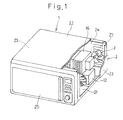
- Fig. 1 is a schematic perspective view of a microwave oven with a top portion of a casing cut out to show the use therein of a transformer according to a preferred embodiment of the present invention;
- Fig. 2 is an exploded view of the transformer used in the microwave oven of Fig. 1;
- Fig. 3 is a side view of the transformer shown in Fig. 2;
- Fig. 4 is a perspective view of the transformer as viewed from bottom thereof; and
- Fig. 5 is a circuit diagram showing a magnetron drive circuit employed in the microwave oven that utilizes the transformer of the present invention.
-
- With reference to the accompanying drawings, a preferred embodiment of the present invention will be described in detail hereinafter. As shown in Fig. 1, a microwave oven 1 includes an oven casing 2 made up of a
bottom wall 21, atop wall 22, a pair ofside walls 23 and arear wall 24, all assembled together to represent a generally rectangular box opening in a forward direction. The casing 2 also has a hingedly supported door for selectively opening or closing a front opening of the casing 2 or an access opening leading into an oven chamber inside the casing 2. - A
transformer 12 is disposed within the instrument compartment and fixedly mounted on thebottom wall 21 of the oven casing 2, with amagnetron 16 positioned above thistransformer 12, and acooling fan 3 is positioned rearwardly of thetransformer 12 and themagnetron 16. Thecooling fan 3 is utilized to introduce air from the outside of the oven casing 2 through adraught window 27 defined in therear wall 24, to thereby blow thetransformer 12 and themagnetron 16 to cool thetransformer 12 and themagnetron 16. The current of cooling air used to cool thetransformer 12 and themagnetron 16 is subsequently vented to the outside of the casing 2 through a vent hole not shown, but defined in one side of thetop wall 22. - As shown in Fig. 2, the
transformer 12 includes acore 18 made up of afirst core piece 18e and asecond core piece 18i positioned one above the other. Thefirst core piece 18e is of a generally E-shaped configuration including a pair of outer legs 18eo connected together by means of a bridge portion and an intermediate leg 18ec extending parallel from the bridge and positioned between the outer legs 18co. Thesecond core piece 18i is of a generally I-shaped configuration and coupled fixedly with thefirst core piece 18e with the outer legs 18eo of thefirst core piece 18i held in contact with thesecond core piece 18i. In assembling thetransformer core 18, a coil ofsecondary winding 14 is mounted around the intermediate leg 18ec, a coil of heater winding 17 is then mounted around the intermediate leg 18ec and, finally, a coil ofprimary winding 13 is mounted around the intermediate leg 18ec, prior to thesecond core piece 18i coupled to thefirst core piece 18e. If required, a portion of the coiledprimary winding 13 which is held in contact with thefirst core piece 18i is covered by an electrically insulating sheet and, similarly, the coiledsecondary winding 14 may, if required, have its outer surface completely covered by an electrically insulating sheet. Thus, the coiledprimary winding 13, the coiledsecondary winding 14 and the coiled heater winding 17 are spaced in a direction axially thereof about the intermediate leg 18ec and positioned in this specific order from below as viewed in Fig. 2. The coiledsecondary winding 14 has starting and terminatinglead ends lead end 14e being connected with aterminal eyelet 14m while the terminatinglead end 14f of the coiledsecondary winding 14 is connected with a generally flag-shapedterminal element 14h. The coiled heater winding 17 also has starting and terminatinglead ends - The coiled
primary winding 13 carries aterminal support 40. Thisterminal support 40 is made of a synthetic resin and secured to a lower end of the coiled primary winding 13 remote from the coiled heater winding 17 by means of an electrically insulatingtransparent tape 50. A self-resettable temperature responsive switch (hereinafter referred to as a "thermostat") 30 has first andsecond lead lines primary winding 13. Thisthermostat 30 is electrically connected directly with the coiledprimary winding 13 and, as clearly shown in Fig. 4, one end of thefirst lead line 31 and alead line 13e continued from the starting end of the coiledprimary winding 13 are electrically connected with each other by means of a soldering technique to thereby define ajunction 35. If desired or required, thethermostat 30 itself may be covered by an electrically insulating sheet. - The
junction 35 between the end of thefirst lead line 31 and thelead line 13e is positioned adjacent an undersurface of theterminal support 40 and is in turn fixed to the coiledprimary winding 13 by means of an electricallyinsulating tape 50 together with theterminal support 40. Theterminal support 40 has first andsecond terminals lead line 13f continued from the terminating lead end of the coiledprimary winding 13 is connected with thefirst terminal 41 whereas thefirst lead line 31 of thethermostat 30 is connected with thesecond terminal 42. Theterminal eyelet 14m connected with thelead line 14e continued from the starting lead end of the coiledsecondary winding 14 is connected with thefirst core piece 18e and, hence, thetransformer core 18 by means of aset screw 18n threaded into a screw hole 18en defined in thesecond core piece 18e as best shown in Fig. 3. - When the coiled
primary winding 13 is mounted on the intermediate leg 18ec of thefirst core piece 18e at a final stage as shown in Fig. 2 with the intermediate leg 18ec received in a center void of the coiledsecondary winding 14, thethermostat 30 is mounted on the intermediate leg 18ec of thefirst core piece 18e and within a center void of the coiledsecondary winding 14 through a gap between an inner periphery of the coiled heater winding 17 and the intermediate leg 18ec, so that thethermostat 30 can have its temperature sensing surface positioned at an upper portion of an inner peripheral face of the coiledsecondary winding 14 and generally intermediate portion in a widthwise direction, indicated by the double headed arrows LR, of the center void of the coiledsecondary winding 14. After thethermostat 30 has been so positioned as hereinabove described with the coiledprimary winding 13 having already been mounted on the intermediate leg 18ec of thetransformer core 18, thesecond core piece 18i is, while being pressed against respective end faces of the outer legs 18eo of thefirst core piece 18e, secured rigidly thereto as at 18m (Fig. 3) by means of a fillet welding technique, to thereby complete thetransformer 12. Theresultant transformer 12 is then mounted on abase plate 19 that is spot-welded to an undersurface of thesecond core piece 18i. Thetransformer 12 having thebase plate 19 fitted thereto is mounted on thebottom wall 21 of the oven casing 2 by means of a plurality of, for example, four, fastening elements such as bolts having been passed through associated mounting holes defined in four corner regions of thebase plate 19. Thus, thetransformer core 18 is grounded to the oven casing 2. - The
transformer 12 assembled in the manner described above is vacuum impregnated with an electrically insulating varnish having a high thermal conductivity. The varnish coats surfaces of thecore 18 and thethermostat 30 and penetrates into the first andsecond windings - Fig. 5 illustrates an electric circuit diagram showing a magnetron drive circuit used in the microwave oven utilizing the
transformer 12 that is assembled as hereinbefore in accordance with the present invention. Referring to Fig. 5, the coiled primary winding 13 of thetransformer 12 is electrically connected with acommercial power source 33 through thethermostat 30 while an output voltage from the coiled secondary winding 14 of thesame transformer 12 is adapted to be rectified and smoothened by a half-wave voltage-doubling rectifying circuit 15 to provide a direct current high voltage which is in turn supplied to amagnetron 16. While a heater of themagnetron 16 preheated by the coiled heater winding 17 built in thetransformer 12, themagnetron 16 generates microwaves when the direct current high voltage is supplied thereto from the half-wave voltage-doubling rectifying circuit 15. - As herein fully described, the primary and
secondary windings core 18 while spaced axially from each other, and the heater winding 17 is wound between the primary andsecondary windings lead line 13f continued from the terminating end of the primary winding 13 is connected with thefirst terminal 41 of theterminal support 40 and thefirst lead line 31 of thethermostat 30 is connected with thesecond terminal 42 of theterminal support 40. Thelead line 13e continued from the starting end of the primary winding 13 is connected with thesecond lead line 32 of thethermostat 30. Thus, thethermostat 30 is electrically connected in series with the primary winding 13 through the lead lines 31 and 32 and is interposed between the secondary winding 14 and thetransformer core 18. Thelead line 14e continued from the starting end of the secondary winding 14 is connected with thetransformer core 18 through theterminal eyelet 14m and thelead line 14f continued from the terminating end of the secondary winding 14 is connected with an input end of the half-wave voltage-doubling rectifying circuit 15 through the flag-shaped terminal element 14h1. The twoopposite lead lines magnetron 16 through the flag-shaped terminal elements 17h1 and 17h2 that are connected therewith. - In the structure described hereinbefore, when the temperature
responsive switch 30 monitoring the temperature of a region between the secondary winding 14 and thetransformer core 18 which will attain the highest temperature detects such temperature exceeding a predetermined temperature, the temperatureresponsive switch 30 is turned off to interrupt supply of the electric power from thepower source 33 to the primary winding 13. Accordingly, any undesirable increase of the temperature of the transformer can advantageously be suppressed and, for this reason, the transformer core can have a reduced size. Also, since the temperature of thetransformer 12 during its normal operation and the highest critical temperature representative of occurrence of the abnormal condition can fall below the currently prescribed temperature limit, thetransformer 12 itself can be assembled compact in size, lightweight and at a reduced cost. In addition, since the temperatureresponsive switch 30 is supported sandwiched between the secondary winding 14 and thetransformer core 18, no extra fastening element is needed to allow it to be supported and retained in position. By way of example, with the transformer designed to meet with the EI-96 standards, if thethermostat 30 of a type that will be switched off when the detected temperature attains 200°C and be reset to an ON stage when the detected temperature falls down to 190°C, attainment of the temperature at the inner peripheral surface of the coiled secondary winding 14 to 200°C can result in interruption of the power supply to the primary winding 13 to thereby suppress any undesirable temperature increase and, accordingly, the normal operating temperature of thetransformer 12 will not exceed the prescribed limit of 200°C and, even in the event of occurrence of the abnormal condition such as failure of the coolingfan 3 to operate normally, the temperature of thetransformer 12 will not increase to a value higher than the prescribed limit of 250°C. - While the highest temperature region of the
transformer 12 may be thought residing at a center area C1 of the cross-section of the secondary winding so far the foregoing embodiment of the present invention is concerned, since the electrically insulating varnish having a thermal conductivity not lower than 0.25 W/m.°C penetrates inwardly of the secondary winding 14, heat evolved at the center area C1 of the cross-section of the secondary winding 14 can be conducted to an outer surface area of the secondary winding 14 efficiently and with no localized variation. In addition, the electrically insulating varnish of such a high thermal conductivity filled in between the temperatureresponsive switch 30 and the inner perimeter of the secondary winding 14 facilitates an efficient transmission of heat evolving at the inner peripheral surfaces of the secondary winding 14 to the temperatureresponsive switch 30. Accordingly, the temperatureresponsive switch 30 is effective to detect the temperature as close to the highest possible temperature of thetransformer 12 as possible accurately and with minimized localized variation that may occur depending on the position where the temperatureresponsive switch 30 is disposed. - Also, since thermal conduction can be facilitated between the
transformer core 18 and each of the primary andsecondary windings transformer core 18 can be effectively suppressed, making it possible to further reduce the size of the transformer core. - Also, since the secondary winding 14 tending to be heated to a temperature higher than that of the primary winding 13 is positioned above the primary winding 13, upward drift of heat from the secondary winding 14 will bring no adverse influence on the primary winding 13 and, in this condition, the temperature
responsive switch 30 detects the temperature at a region between the secondary winding 14 and thetransformer core 18 which will attain the highest temperature detects such temperature exceeding a predetermined temperature. In addition, since theterminal support 40 is secured to the primary winding 13, the temperatureresponsive switch 30 connected with the primary winding 13 can be positioned considerably close to theterminal support 40, making it possible to use relativelyshort lead lines responsive switch 30 that are connected with theterminal support 40 while eliminating the necessity of use of any extra connection terminal element necessary to support thejunction 35 between thelead line 13e of the primary winding 13 and thelead line 32 of the temperatureresponsive switch 30. - Yet, as shown in Fig. 1, since the
transformer 12 is mounted in the oven casing 2 in such a manner that a mounting surface of thethermostat 30 can be oriented downstream of the flow of the cooling air, the cooling air will not impinge directly on the temperatureresponsive switch 30 and, accordingly, the position of the temperatureresponsive switch 30 will be the area where the highest possible temperature in thetransformer 12 may be attained. In other words, the temperatureresponsive switch 30 can properly detect the temperature of the area of thetransformer 12 where the highest possible temperature will be attained. - It is to be noted that in the foregoing description of the preferred embodiment, the secondary winding 14 is assumed to attain the highest possible temperature in the
transformer 12. However, depending on the design trade-off such as a current or voltage ratio between the primary winding 13 and the secondary winding 14, it may occur that the primary winding 13 will evolve heat of a temperature higher than that evolving in the secondary winding 14. In such case, the temperatureresponsive switch 30 has to be intervened between the primary winding 13 and thetransformer core 18 so that the temperature as close to the highest possible temperature of thetransformer 12 as possible can be detected. - In addition, while in the foregoing description of the preferred embodiment the transformer core has been described including the generally E-shaped core piece and the generally I-shaped core piece. However, the use may be made of two generally E-shaped core pieces for the transformer core.
- Furthermore, the present invention can be equally applied to any transformer designed according to a different standard prescribing the different highest permissible operating temperature and the different highest critical temperature. Also, the transformer embodying the present invention is not always limited to the use for driving the magnetron, but may be used in association with any transformer having a higher operating temperature.
- The transformer embodying the present invention has been described as that employed in the microwave oven. In such case, as shown in Fig. 1, if the electronic oven 1, which is an example of electric appliances, includes an oven casing 2 accommodating therein both a
magnetron 16, which is an electronic element adapted to be driven by thetransformer 12, and a coolingfan 3 for cooling thetransformer 12, and wherein thethermostat 30 for thetransformer 12 is mounted in the oven casing 2 in such a manner that a mounting surface of thethermostat 30 can be oriented downstream of the flow of the cooling air, i.e., on one side of thetransformer 12 remote from the side thereof where the cooling air from the coolingfan 3 impinges, the electric appliance can be assembled compact and lightweight and at a reduced cost owing to compactization of thetransformer 12. - Although the present invention has been fully described in connection with the preferred embodiments thereof with reference to the accompanying drawings which are used only for the purpose of illustration, those skilled in the art will readily conceive numerous changes and modifications within the framework of obviousness upon the reading of the specification herein presented of the present invention. Accordingly, such changes and modifications are, unless they depart from the scope of the present invention as delivered from the claims annexed hereto, to be construed as included therein.
Claims (5)
- Transformer (12) having a temperature detecting capability, which transformer (12) comprises:wherein the primary winding (13) and the secondary winding (14) are spaced from each other in a direction axially thereof; anda transformer core (18);primary and secondary windings (13,14) wound around the transformer core (18); anda temperature responsive switch (30) connected in series with the primary winding (13) and adapted to be switched off in response to increase of a temperature to a value equal to or higher than a predetermined value;
wherein the temperature responsive switch (30), having a temperature sensing surface is positioned between one of the primary and secondary windings (13,14) and the transformer core (18),
characterized in that the temperature sensing surface is positioned on an inner peripheral face of one of the primary and secondary windings (13,14) and wherein the transformer core (18), the primary winding (13), the secondary winding (14) and the temperature responsive switch (30) are impregnated with an electrically insulating varnish having a thermal conductivity not lower than 0.25 W/m °C. - The transformer (12) having the temperature detecting capability as claimed in Claim 1, wherein the transformer core (18) includes a generally E-shaped first core piece (18e) and a generally I-shaped or E-shaped second core piece (18i) positioned one above the other, said first core piece (18e) having an intermediate leg (18ec) around which the primary and secondary windings (13,14) are wound with the secondary winding (14) positioned above the primary winding (13).
- The transformer (12) having the temperature detecting capability as claimed in Claim 1, wherein the primary winding (13) has a terminal support (40) fitted thereto, said terminal support (40) having a first terminal (41) with which one end of the primary winding (13) is connected, and a second terminal (42) connected with one of lead lines (31) extending from the temperature responsive switch, the other of the lead lines (32) of the temperature responsive switch (30) being connected with the other end of the primary winding (13).
- The transformer (12) having the temperature detecting capability as claimed in Claim 3, wherein a junction (35) between the other end of the primary winding (13) and the other of the lead lines (32) of the temperature responsive switch (30) is supported by the terminal support (40).
- An electric appliance (1) which comprises:wherein the temperature responsive switch (30) incorporated in the transformer (12) is disposed on one side of the transformer (12) remote from the opposite side of the transformer (12) where a current of the cooling air induced by the cooling fan (3) impinges.a casing (2);a transformer (12) as defined in any one of Claims 1 to 4 and accommodated within the casing (2);an electric element (16) accommodated within the casing (2) and adapted to be driven by the transformer (12); anda cooling fan (3) disposed within the casing (2) for cooling the transformer (12);
Priority Applications (2)
| Application Number | Priority Date | Filing Date | Title |
|---|---|---|---|
| EP20020254013 EP1372165B1 (en) | 2002-06-10 | 2002-06-10 | Transformer having a temperature detecting capability and an electric appliance utilizing the same |
| DE2002605468 DE60205468T2 (en) | 2002-06-10 | 2002-06-10 | Transformer with temperature detector and electrical device using it |
Applications Claiming Priority (1)
| Application Number | Priority Date | Filing Date | Title |
|---|---|---|---|
| EP20020254013 EP1372165B1 (en) | 2002-06-10 | 2002-06-10 | Transformer having a temperature detecting capability and an electric appliance utilizing the same |
Publications (2)
| Publication Number | Publication Date |
|---|---|
| EP1372165A1 EP1372165A1 (en) | 2003-12-17 |
| EP1372165B1 true EP1372165B1 (en) | 2005-08-10 |
Family
ID=29558411
Family Applications (1)
| Application Number | Title | Priority Date | Filing Date |
|---|---|---|---|
| EP20020254013 Expired - Lifetime EP1372165B1 (en) | 2002-06-10 | 2002-06-10 | Transformer having a temperature detecting capability and an electric appliance utilizing the same |
Country Status (2)
| Country | Link |
|---|---|
| EP (1) | EP1372165B1 (en) |
| DE (1) | DE60205468T2 (en) |
Families Citing this family (5)
| Publication number | Priority date | Publication date | Assignee | Title |
|---|---|---|---|---|
| KR20130027340A (en) * | 2011-09-07 | 2013-03-15 | 삼성전자주식회사 | Microwave range |
| CN104373970A (en) * | 2014-11-13 | 2015-02-25 | 广东美的厨房电器制造有限公司 | Microwave oven |
| IT201800007694A1 (en) * | 2018-07-31 | 2020-01-31 | Meta System Spa | WRAPPED COMPONENT |
| CN111430136B (en) * | 2020-05-06 | 2025-01-14 | 深圳市鸿宝电气有限公司 | A dry-type transformer load self-diagnosis protection device |
| CN120376293B (en) * | 2025-04-29 | 2025-11-25 | 内蒙古寰泰节能环保科技有限公司 | A high-voltage energy-saving device with a three-dimensional wound core structure |
Family Cites Families (4)
| Publication number | Priority date | Publication date | Assignee | Title |
|---|---|---|---|---|
| US3675081A (en) * | 1970-04-27 | 1972-07-04 | Gen Electric | Thermal-overload protective arrangement for inductive devices |
| JP3153261B2 (en) * | 1991-03-28 | 2001-04-03 | 日本電産株式会社 | Bobbin for transformer |
| JPH11195550A (en) * | 1998-01-06 | 1999-07-21 | Kureha Chem Ind Co Ltd | Coil part |
| MY120386A (en) * | 1999-07-28 | 2005-10-31 | Samsung Electronics Co Ltd | High voltage transformer for microware oven and method of manufacturing therefor. |
-
2002
- 2002-06-10 DE DE2002605468 patent/DE60205468T2/en not_active Expired - Lifetime
- 2002-06-10 EP EP20020254013 patent/EP1372165B1/en not_active Expired - Lifetime
Also Published As
| Publication number | Publication date |
|---|---|
| DE60205468T2 (en) | 2006-02-09 |
| EP1372165A1 (en) | 2003-12-17 |
| DE60205468D1 (en) | 2005-09-15 |
Similar Documents
| Publication | Publication Date | Title |
|---|---|---|
| EP0477633B1 (en) | High frequency heating apparatus utilizing inverter power supply | |
| US5509786A (en) | Thermal protector mounting structure for hermetic refrigeration compressors | |
| US6677562B2 (en) | High-frequency heating apparatus and cooling system for magnetron-driving power supply utilized in the apparatus | |
| US20020038795A1 (en) | Power supply apparatus | |
| EP1372165A1 (en) | Transformer having a temperature detecting capability and an electric appliance utilizing the same | |
| JP3799143B2 (en) | Induction heating cooker | |
| EP3930425B1 (en) | Cooking appliance | |
| US7365294B2 (en) | Microwave oven | |
| KR102827604B1 (en) | Induction heating cooker | |
| JPH03295191A (en) | Microwave oven | |
| JP3257421B2 (en) | Induction heating cooker | |
| US7041900B2 (en) | Inlet with heat-insulation function | |
| JP4176491B2 (en) | Electromagnetic induction heating cooker | |
| JPS6333054Y2 (en) | ||
| KR20220160924A (en) | Electric range and method for controlling the same | |
| JPH01227664A (en) | Protective system and device for inverter | |
| JP3257236B2 (en) | Cooking device | |
| JPH02239818A (en) | Thermosensor for cooker | |
| JPH1012464A (en) | Electromagnetic apparatus | |
| EP4712695A1 (en) | Electric range | |
| KR940008522B1 (en) | Microwave Safety Device | |
| JP2004108677A (en) | Safety devices and air conditioners | |
| CN121363528A (en) | Compressor temperature protection module and compressor temperature protection system | |
| JPH09311729A (en) | Power control device | |
| JP2003100433A (en) | Induction heating cooker |
Legal Events
| Date | Code | Title | Description |
|---|---|---|---|
| PUAI | Public reference made under article 153(3) epc to a published international application that has entered the european phase |
Free format text: ORIGINAL CODE: 0009012 |
|
| AK | Designated contracting states |
Kind code of ref document: A1 Designated state(s): AT BE CH CY DE DK ES FI FR GB GR IE IT LI LU MC NL PT SE TR |
|
| AX | Request for extension of the european patent |
Extension state: AL LT LV MK RO SI |
|
| 17P | Request for examination filed |
Effective date: 20040416 |
|
| 17Q | First examination report despatched |
Effective date: 20040616 |
|
| AKX | Designation fees paid |
Designated state(s): DE FR GB |
|
| GRAP | Despatch of communication of intention to grant a patent |
Free format text: ORIGINAL CODE: EPIDOSNIGR1 |
|
| GRAS | Grant fee paid |
Free format text: ORIGINAL CODE: EPIDOSNIGR3 |
|
| GRAA | (expected) grant |
Free format text: ORIGINAL CODE: 0009210 |
|
| AK | Designated contracting states |
Kind code of ref document: B1 Designated state(s): DE FR GB |
|
| REG | Reference to a national code |
Ref country code: GB Ref legal event code: FG4D |
|
| REF | Corresponds to: |
Ref document number: 60205468 Country of ref document: DE Date of ref document: 20050915 Kind code of ref document: P |
|
| ET | Fr: translation filed | ||
| PLBE | No opposition filed within time limit |
Free format text: ORIGINAL CODE: 0009261 |
|
| STAA | Information on the status of an ep patent application or granted ep patent |
Free format text: STATUS: NO OPPOSITION FILED WITHIN TIME LIMIT |
|
| 26N | No opposition filed |
Effective date: 20060511 |
|
| REG | Reference to a national code |
Ref country code: FR Ref legal event code: PLFP Year of fee payment: 15 |
|
| REG | Reference to a national code |
Ref country code: FR Ref legal event code: PLFP Year of fee payment: 16 |
|
| REG | Reference to a national code |
Ref country code: FR Ref legal event code: PLFP Year of fee payment: 17 |
|
| PGFP | Annual fee paid to national office [announced via postgrant information from national office to epo] |
Ref country code: DE Payment date: 20210413 Year of fee payment: 20 Ref country code: FR Payment date: 20210629 Year of fee payment: 20 |
|
| PGFP | Annual fee paid to national office [announced via postgrant information from national office to epo] |
Ref country code: GB Payment date: 20210412 Year of fee payment: 20 |
|
| REG | Reference to a national code |
Ref country code: DE Ref legal event code: R071 Ref document number: 60205468 Country of ref document: DE |
|
| REG | Reference to a national code |
Ref country code: GB Ref legal event code: PE20 Expiry date: 20220609 |
|
| PG25 | Lapsed in a contracting state [announced via postgrant information from national office to epo] |
Ref country code: GB Free format text: LAPSE BECAUSE OF EXPIRATION OF PROTECTION Effective date: 20220609 |
|
| REG | Reference to a national code |
Ref country code: DE Ref legal event code: R081 Ref document number: 60205468 Country of ref document: DE Owner name: DIAMOND&ZEBRA ELECTRIC MFG.CO., LTD., JP Free format text: FORMER OWNER: TABUCHI ELECTRIC CO., LTD., SANDA, HYOGO, JP |