EP1371821A1 - Oil sump - Google Patents
Oil sump Download PDFInfo
- Publication number
- EP1371821A1 EP1371821A1 EP03013239A EP03013239A EP1371821A1 EP 1371821 A1 EP1371821 A1 EP 1371821A1 EP 03013239 A EP03013239 A EP 03013239A EP 03013239 A EP03013239 A EP 03013239A EP 1371821 A1 EP1371821 A1 EP 1371821A1
- Authority
- EP
- European Patent Office
- Prior art keywords
- sump
- oil
- engine
- trays
- tunnel
- Prior art date
- Legal status (The legal status is an assumption and is not a legal conclusion. Google has not performed a legal analysis and makes no representation as to the accuracy of the status listed.)
- Granted
Links
- 239000003921 oil Substances 0.000 claims abstract description 42
- 239000010705 motor oil Substances 0.000 claims abstract description 4
- 238000005266 casting Methods 0.000 claims description 4
- 230000001419 dependent effect Effects 0.000 claims 1
- 230000005540 biological transmission Effects 0.000 description 1
- 230000037431 insertion Effects 0.000 description 1
- 238000003780 insertion Methods 0.000 description 1
- 239000002184 metal Substances 0.000 description 1
- 238000004806 packaging method and process Methods 0.000 description 1
- 239000002245 particle Substances 0.000 description 1
Images
Classifications
-
- F—MECHANICAL ENGINEERING; LIGHTING; HEATING; WEAPONS; BLASTING
- F01—MACHINES OR ENGINES IN GENERAL; ENGINE PLANTS IN GENERAL; STEAM ENGINES
- F01M—LUBRICATING OF MACHINES OR ENGINES IN GENERAL; LUBRICATING INTERNAL COMBUSTION ENGINES; CRANKCASE VENTILATING
- F01M11/00—Component parts, details or accessories, not provided for in, or of interest apart from, groups F01M1/00 - F01M9/00
- F01M11/0004—Oilsumps
-
- F—MECHANICAL ENGINEERING; LIGHTING; HEATING; WEAPONS; BLASTING
- F01—MACHINES OR ENGINES IN GENERAL; ENGINE PLANTS IN GENERAL; STEAM ENGINES
- F01M—LUBRICATING OF MACHINES OR ENGINES IN GENERAL; LUBRICATING INTERNAL COMBUSTION ENGINES; CRANKCASE VENTILATING
- F01M11/00—Component parts, details or accessories, not provided for in, or of interest apart from, groups F01M1/00 - F01M9/00
- F01M11/0004—Oilsumps
- F01M2011/0066—Oilsumps with passages in the wall, e.g. for axles or fluid passages
-
- F—MECHANICAL ENGINEERING; LIGHTING; HEATING; WEAPONS; BLASTING
- F01—MACHINES OR ENGINES IN GENERAL; ENGINE PLANTS IN GENERAL; STEAM ENGINES
- F01M—LUBRICATING OF MACHINES OR ENGINES IN GENERAL; LUBRICATING INTERNAL COMBUSTION ENGINES; CRANKCASE VENTILATING
- F01M11/00—Component parts, details or accessories, not provided for in, or of interest apart from, groups F01M1/00 - F01M9/00
- F01M11/0004—Oilsumps
- F01M2011/0079—Oilsumps with the oil pump integrated or fixed to sump
Definitions
- the present invention relates to an oil sump for the engine of an agricultural vehicle.
- the oil sump or oil pan of the engine is constructed as a heavy item made of cast metal which is used to add to the stiffness of the engine block.
- the substantial oil sump adds to the overall height of the engine and leads to packaging problems in particular in an agricultural vehicle having a four-wheel drive system because the propeller shaft leading to the front axle needs to pass directly beneath the sump. This means that the engine block and with it the entire drive train have to be raised to allow clearance for the propeller shaft.
- the present invention seeks to enable the sump to have a sufficient oil capacity to meet the needs of the engine without having to raise the whole engine block.
- an oil sump for an engine of a vehicle wherein the underside of the sump is formed with a longitudinally extending downwardly concave tunnel to accommodate a propeller shaft, the tunnel dividing the interior of the sump into two oil trays arranged one on each side of the tunnel.
- the sump of the present invention is formed as a saddle that fits over the propeller shaft, so that instead of falling into a single tray positioned entirely above the propeller shaft, the engine oil collects in two trays which straddle the propeller shaft.
- two separate oil passages may be provided in the sump that connect the respective trays to a common oil recirculation duct.
- the latter duct communicates with the intake side of the engine oil pump.
- the sump is formed as a casting and the passages are formed as an integral part of the casting. It is still further preferred for the recirculation duct also to be cast as part of the sump.
- the junction between the passages and the recirculation duct may conveniently be formed as a chamber into which the passages and the duct open.
- a screen or filter may suitably be press-fitted into the chamber to remove larger particles from the oil before it is recirculated to the engine.
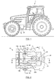
- the sump 10 shown in the drawings has a flange 12 at its upper end which in use is bolted to the underside of an engine block of an agricultural tractor 1 by means of bolts that pass through holes 14 formed at intervals in the flange 12.
- the bottom of the oil tray of the sump of the preferred embodiment of the invention is shaped like a saddle.
- the underside of the sump defines a concave tunnel 16 that faces downwards and within which the sump oil collects in two elongate trays 18a and 18b that lie one on each side of the tunnel 16.
- the oil that drips into the trays from the engine block is recirculated by means of an oil pump (not shown) that is mounted on the engine block and draws oil from the two trays 18a and 18b.
- an oil pump (not shown) that is mounted on the engine block and draws oil from the two trays 18a and 18b.
- two passages 20a and 20b are cast into the block and lead from the respective trays 18a and 18b to a common plenum or chamber 22.
- a recirculation duct 24 having a mouth 26 that opens into the flange 12 is also cast as part of the sump to connect the chamber 22 to the oil pump.
- a gasket may be provided around the mouth 26 for making the connection between the duct 24 and the oil pump oiltight.
- a filter 28 is press-fitted into the chamber 22 so that oil drawn from both oil trays 18a and 18b has to pass through the filter 28 before entering the duct 24 for recirculation by the oil pump.
- the tunnel on the underside of the sump is dimensioned to accommodate a propeller shaft as represented in dotted lines at 30 in Figure 3.
- a propeller shaft as represented in dotted lines at 30 in Figure 3.
- the oil trays 18a and 18b can straddle the propeller shaft 30 that leads to the front axle instead of being located above it. This avoids the need for the engine and transmission to be raised to allow clearance for the propeller shaft 30.
- the illustrated sump 10 is also formed with an access tube 32 for a dipstick.
- the positioning of the access tube permits the use of a short and therefore convenient dipstick that reaches directly into the tray 18b.
- the provision of the duct 24 as integral part of the sump 10 reduces the number of components as otherwise a separate suction tube would be required. Furthermore, it facilitates assembly of the sump 10 in the narrow space inbetween the engine block and the propeller shaft 30, enabling it to be carried out as a blind operation, without running the risk of damaging the suction equipment.
- passages 20a and 20b reach fairly deep into the oil trays 18a and 18b, ensuring that even with an exceptional low level of oil in the sump 10 or on a transverse incline, sufficient oil is present to prevent air from entering the oil pump.
Landscapes
- Engineering & Computer Science (AREA)
- Mechanical Engineering (AREA)
- General Engineering & Computer Science (AREA)
- Lubrication Details And Ventilation Of Internal Combustion Engines (AREA)
- Measurement Of The Respiration, Hearing Ability, Form, And Blood Characteristics Of Living Organisms (AREA)
- Devices For Conveying Motion By Means Of Endless Flexible Members (AREA)
- Compressor (AREA)
- General Details Of Gearings (AREA)
Abstract
Description
- The present invention relates to an oil sump for the engine of an agricultural vehicle.
- Many agricultural vehicles, such as tractors, have so-called structural engines, that is to say engines that form a structural part of the vehicle chassis. In such vehicles, the engine does not only act as the prime mover for driving the vehicle but is relied upon to give strength to the vehicle chassis. The oil sump or oil pan of the engine is constructed as a heavy item made of cast metal which is used to add to the stiffness of the engine block.
- The substantial oil sump adds to the overall height of the engine and leads to packaging problems in particular in an agricultural vehicle having a four-wheel drive system because the propeller shaft leading to the front axle needs to pass directly beneath the sump. This means that the engine block and with it the entire drive train have to be raised to allow clearance for the propeller shaft.
- The present invention seeks to enable the sump to have a sufficient oil capacity to meet the needs of the engine without having to raise the whole engine block.
- In accordance with the present invention, there is provided an oil sump for an engine of a vehicle, wherein the underside of the sump is formed with a longitudinally extending downwardly concave tunnel to accommodate a propeller shaft, the tunnel dividing the interior of the sump into two oil trays arranged one on each side of the tunnel.
- The sump of the present invention is formed as a saddle that fits over the propeller shaft, so that instead of falling into a single tray positioned entirely above the propeller shaft, the engine oil collects in two trays which straddle the propeller shaft.
- To allow oil to be drawn from both trays, two separate oil passages may be provided in the sump that connect the respective trays to a common oil recirculation duct. The latter duct communicates with the intake side of the engine oil pump.
- Preferably, the sump is formed as a casting and the passages are formed as an integral part of the casting. It is still further preferred for the recirculation duct also to be cast as part of the sump.
- The junction between the passages and the recirculation duct may conveniently be formed as a chamber into which the passages and the duct open. A screen or filter may suitably be press-fitted into the chamber to remove larger particles from the oil before it is recirculated to the engine.
- The invention will now be described further, by way of example, with reference to the accompanying drawings, in which :
- Figure 1 is a side view of an agricultural tractor comprising a sump in accordance with the present invention;
- Figure 2 is a plan view from above of a sump embodying the present invention;
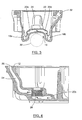
- Figure 3 is a section taken along the line III-III in Figure 2; and
- Figure 4 is a section taken along the line IV-IV in Figure 2 after insertion of a filter.
-
- The
sump 10 shown in the drawings has aflange 12 at its upper end which in use is bolted to the underside of an engine block of anagricultural tractor 1 by means of bolts that pass throughholes 14 formed at intervals in theflange 12. - Whereas a conventional sump would be formed with a flat-bottomed drip tray extending across the width of the engine block, the bottom of the oil tray of the sump of the preferred embodiment of the invention, as is best shown in Figure 3, is shaped like a saddle. In particular, the underside of the sump defines a
concave tunnel 16 that faces downwards and within which the sump oil collects in twoelongate trays tunnel 16. - The oil that drips into the trays from the engine block is recirculated by means of an oil pump (not shown) that is mounted on the engine block and draws oil from the two
trays passages respective trays chamber 22. Arecirculation duct 24 having amouth 26 that opens into theflange 12, is also cast as part of the sump to connect thechamber 22 to the oil pump. A gasket may be provided around themouth 26 for making the connection between theduct 24 and the oil pump oiltight. - A
filter 28 is press-fitted into thechamber 22 so that oil drawn from bothoil trays filter 28 before entering theduct 24 for recirculation by the oil pump. - The tunnel on the underside of the sump is dimensioned to accommodate a propeller shaft as represented in dotted lines at 30 in Figure 3. In this way, the
oil trays propeller shaft 30 that leads to the front axle instead of being located above it. This avoids the need for the engine and transmission to be raised to allow clearance for thepropeller shaft 30. - The illustrated
sump 10 is also formed with anaccess tube 32 for a dipstick. The positioning of the access tube permits the use of a short and therefore convenient dipstick that reaches directly into thetray 18b. - The provision of the
duct 24 as integral part of thesump 10 reduces the number of components as otherwise a separate suction tube would be required. Furthermore, it facilitates assembly of thesump 10 in the narrow space inbetween the engine block and thepropeller shaft 30, enabling it to be carried out as a blind operation, without running the risk of damaging the suction equipment. - The entrances of
passages oil trays sump 10 or on a transverse incline, sufficient oil is present to prevent air from entering the oil pump.
Claims (9)
- An oil sump for an engine of a vehicle, and
characterized in that the underside of the sump (10) is formed with a longitudinally extending downwardly concave tunnel (16) to accommodate a propeller shaft (30), the tunnel (16) dividing the interior of the sump (10) into two oil trays (18a, 18b) arranged one on each side of the tunnel (16). - An oil sump according to claim 1, characterized in that two separate oil passages (20a, 20b) are provided in the sump (10) that connect the respective trays (18a, 18b) to a common oil recirculation duct (24).
- An oil sump according to claim 2, characterized in that the sump (10) is formed as a casting and the passages (20a, 20b) are formed as an integral part of the casting.
- An oil sump according to claim 3, characterized in that the recirculation duct (24) is also cast as part of the sump (10).
- An oil sump according to any of the claims 2 to 5, characterized in that the junction between the passages (20a, 20b) and the recirculation duct (24) is formed as a chamber (22) into which the passages (20a, 20b) and the duct (24) open.
- An oil sump according to claim 5, characterized in that a filter (28) is mounted in the chamber (22) to filter oil drawn from the trays (18a, 18b) for recirculation to the engine.
- An oil sump according to claim 2 and any claim dependent directly or indirectly therefrom, characterized in that the recirculation duct (24) has a mouth (26) that opens into a mounting flange (12) of the sump (10) for connecting said duct (24) to an engine oil pump.
- An oil sump according to any of the preceding claims, characterized in that the sump (10) is attached to a structural engine of an agricultural vehicle (1).
- An oil sump according to claim 8, characterized in that the propeller shaft (30) drives the front wheels of the vehicle (1).
Applications Claiming Priority (2)
| Application Number | Priority Date | Filing Date | Title |
|---|---|---|---|
| GB0213535A GB2389625A (en) | 2002-06-13 | 2002-06-13 | Oil sump |
| GB0213535 | 2002-06-13 |
Publications (2)
| Publication Number | Publication Date |
|---|---|
| EP1371821A1 true EP1371821A1 (en) | 2003-12-17 |
| EP1371821B1 EP1371821B1 (en) | 2008-03-12 |
Family
ID=9938465
Family Applications (1)
| Application Number | Title | Priority Date | Filing Date |
|---|---|---|---|
| EP03013239A Expired - Lifetime EP1371821B1 (en) | 2002-06-13 | 2003-06-12 | Oil sump |
Country Status (5)
| Country | Link |
|---|---|
| US (1) | US6895920B2 (en) |
| EP (1) | EP1371821B1 (en) |
| AT (1) | ATE389099T1 (en) |
| DE (1) | DE60319630T2 (en) |
| GB (1) | GB2389625A (en) |
Cited By (3)
| Publication number | Priority date | Publication date | Assignee | Title |
|---|---|---|---|---|
| EP4407150A1 (en) * | 2023-01-24 | 2024-07-31 | Schwäbische Hüttenwerke Automotive GmbH | Oil sump, in particular oil filter module, with a multipart housing |
| WO2026004227A1 (en) * | 2024-06-27 | 2026-01-02 | 株式会社クボタ | Engine oil pan |
| US12535022B2 (en) | 2023-01-24 | 2026-01-27 | Schwäbische Hüttenwerke Automotive GmbH | Oil sump, in particular oil filter module, with a multi-part housing |
Families Citing this family (8)
| Publication number | Priority date | Publication date | Assignee | Title |
|---|---|---|---|---|
| JP4327756B2 (en) * | 2005-03-22 | 2009-09-09 | トヨタ自動車株式会社 | Hydraulic circuit device and hybrid drive device using the same |
| US20080257649A1 (en) * | 2007-04-17 | 2008-10-23 | Sameck Michael J | Oil pan with an integrally formed tube assembly for high pressure oil transport |
| US20100147253A1 (en) * | 2008-12-11 | 2010-06-17 | International Engine Intellectual Property Company, Llc | Oil Pan |
| US20100224450A1 (en) * | 2009-03-04 | 2010-09-09 | Cummins Inc. | Reversible oil pan with integrated oil suction tube |
| GB201103262D0 (en) * | 2011-02-25 | 2011-04-13 | Mahle Int Gmbh | A crankshaft |
| DE102011104017A1 (en) * | 2011-06-11 | 2012-12-13 | Audi Ag | Container for a service medium of a motor vehicle |
| GB2548425B (en) * | 2016-02-15 | 2020-07-01 | A Clark Mathew | Two-part structural oil pan |
| GB2592617B (en) * | 2020-03-03 | 2022-06-22 | Perkins Engines Co Ltd | Tunnel type sump with oil intake valve assembly |
Citations (5)
| Publication number | Priority date | Publication date | Assignee | Title |
|---|---|---|---|---|
| JPS5911923A (en) * | 1982-07-09 | 1984-01-21 | Iseki & Co Ltd | Front power taking-out apparatus for tractor |
| JPS5954718A (en) * | 1982-09-21 | 1984-03-29 | Yanmar Diesel Engine Co Ltd | Oil pan of engine for front-wheel-drive tractor |
| JPH0763032A (en) * | 1993-08-27 | 1995-03-07 | Kubota Corp | Oil pan device for vehicle engine |
| JPH11101117A (en) * | 1997-09-26 | 1999-04-13 | Iseki & Co Ltd | Engine lubrication oil circulation device |
| JPH11229841A (en) * | 1998-02-19 | 1999-08-24 | Iseki & Co Ltd | Engine oil pan |
Family Cites Families (12)
| Publication number | Priority date | Publication date | Assignee | Title |
|---|---|---|---|---|
| FI71097C (en) * | 1982-01-29 | 1991-04-23 | Valmet Oy | KONSTRUKTION PAO TRAKTOR, I SYNNERHET JORDBRUKSTRAKTOR. |
| GB2115484B (en) * | 1982-02-25 | 1985-01-16 | Massey Ferguson Perkins Ltd | The sump |
| JPS5954716A (en) | 1982-09-24 | 1984-03-29 | Toyota Motor Corp | Valve lock mechanism for variable cylinder engine |
| IT214888Z2 (en) | 1988-10-07 | 1990-07-04 | Fiat Auto Spa | LIGHT ALLOY OIL PAN FOR AN INTERNAL COMBUSTION ENGINE |
| EP0445164B1 (en) * | 1988-11-25 | 1992-07-15 | ZF FRIEDRICHSHAFEN Aktiengesellschaft | Installation for a steerable rigid axle on a tractor chassis |
| DE4016968A1 (en) | 1990-05-25 | 1991-11-28 | Kloeckner Humboldt Deutz Ag | Oil sump for IC engine - has intake pipe mfd. as integral feature |
| US5601060A (en) * | 1996-03-26 | 1997-02-11 | Navistar International Transportation Corp. | Cast oil pan for internal combustion engine |
| IT1289756B1 (en) | 1996-12-17 | 1998-10-16 | Fiat Auto Spa | INTAKE OF LUBRICATION OIL FOR INTERNAL COMBUSTION ENGINE. |
| CA2325405C (en) * | 1998-03-27 | 2010-04-20 | Tesma International Inc. | Apparatus for die casting an internal passageway and a product manufactured therewith |
| US6041752A (en) | 1998-11-04 | 2000-03-28 | Technology Holdings, Inc. | Moldable integrated oil pan and suction tube for an internal combustion engine |
| US6290843B1 (en) | 2000-06-07 | 2001-09-18 | Brian Thomas Lee | Oil sump with integral filter |
| MY137444A (en) * | 2000-12-21 | 2009-01-30 | Petroliam Nasional Berhad | Oil pan for automobile engine |
-
2002
- 2002-06-13 GB GB0213535A patent/GB2389625A/en not_active Withdrawn
-
2003
- 2003-06-11 US US10/459,637 patent/US6895920B2/en not_active Expired - Lifetime
- 2003-06-12 DE DE60319630T patent/DE60319630T2/en not_active Expired - Lifetime
- 2003-06-12 EP EP03013239A patent/EP1371821B1/en not_active Expired - Lifetime
- 2003-06-12 AT AT03013239T patent/ATE389099T1/en not_active IP Right Cessation
Patent Citations (5)
| Publication number | Priority date | Publication date | Assignee | Title |
|---|---|---|---|---|
| JPS5911923A (en) * | 1982-07-09 | 1984-01-21 | Iseki & Co Ltd | Front power taking-out apparatus for tractor |
| JPS5954718A (en) * | 1982-09-21 | 1984-03-29 | Yanmar Diesel Engine Co Ltd | Oil pan of engine for front-wheel-drive tractor |
| JPH0763032A (en) * | 1993-08-27 | 1995-03-07 | Kubota Corp | Oil pan device for vehicle engine |
| JPH11101117A (en) * | 1997-09-26 | 1999-04-13 | Iseki & Co Ltd | Engine lubrication oil circulation device |
| JPH11229841A (en) * | 1998-02-19 | 1999-08-24 | Iseki & Co Ltd | Engine oil pan |
Non-Patent Citations (5)
| Title |
|---|
| PATENT ABSTRACTS OF JAPAN vol. 008, no. 096 (M - 294) 4 May 1984 (1984-05-04) * |
| PATENT ABSTRACTS OF JAPAN vol. 008, no. 158 (M - 311) 21 July 1984 (1984-07-21) * |
| PATENT ABSTRACTS OF JAPAN vol. 1995, no. 06 31 July 1995 (1995-07-31) * |
| PATENT ABSTRACTS OF JAPAN vol. 1999, no. 09 30 July 1999 (1999-07-30) * |
| PATENT ABSTRACTS OF JAPAN vol. 1999, no. 13 30 November 1999 (1999-11-30) * |
Cited By (3)
| Publication number | Priority date | Publication date | Assignee | Title |
|---|---|---|---|---|
| EP4407150A1 (en) * | 2023-01-24 | 2024-07-31 | Schwäbische Hüttenwerke Automotive GmbH | Oil sump, in particular oil filter module, with a multipart housing |
| US12535022B2 (en) | 2023-01-24 | 2026-01-27 | Schwäbische Hüttenwerke Automotive GmbH | Oil sump, in particular oil filter module, with a multi-part housing |
| WO2026004227A1 (en) * | 2024-06-27 | 2026-01-02 | 株式会社クボタ | Engine oil pan |
Also Published As
| Publication number | Publication date |
|---|---|
| EP1371821B1 (en) | 2008-03-12 |
| US6895920B2 (en) | 2005-05-24 |
| US20040069265A1 (en) | 2004-04-15 |
| GB2389625A (en) | 2003-12-17 |
| DE60319630D1 (en) | 2008-04-24 |
| ATE389099T1 (en) | 2008-03-15 |
| GB0213535D0 (en) | 2002-07-24 |
| DE60319630T2 (en) | 2008-11-13 |
Similar Documents
| Publication | Publication Date | Title |
|---|---|---|
| EP1371821B1 (en) | Oil sump | |
| US5062500A (en) | Low profile cart for the insitu collection filteration and recycle of fluids from machinery | |
| US6217758B1 (en) | Oil sump arrangement with integral filter and heat exchanger | |
| US6143169A (en) | Sump arrangement with baffling | |
| US20190120366A1 (en) | Air intake system for an off-road vehicle | |
| EP2014955B1 (en) | Oil strainer of transmission | |
| US5439585A (en) | Oil filtering device for motor bicycle | |
| US6782965B2 (en) | Truck chassis configuration | |
| US6187185B1 (en) | Filter arrangement for liquids | |
| CN110382856A (en) | Vehicle with air filter Access panel | |
| US6796283B1 (en) | Oiling system for an internal combustion engine | |
| CN115451109A (en) | Axle assembly with lubricant reservoir | |
| US5879140A (en) | Oil pump pickup device for use with an internal combustion engine | |
| US11592102B2 (en) | Transmission lubrication system | |
| US20090057064A1 (en) | Oil pan structure and internal combustion engine | |
| JP2009222061A (en) | Internal combustion engine | |
| JP4023965B2 (en) | Lubricating device for internal combustion engine | |
| EP1775433B1 (en) | Adaptor in combination with a crankcase, oil filter in combination with the crankcase and motorcycle including the oil filter | |
| JP2000136868A (en) | Transfer case structure | |
| US10604007B2 (en) | Drive-shaft arrangement for use on a drive vehicle, in particular a tractor, with an automatic clutch system for intermediate-axle attachment units | |
| US2039002A (en) | Oil pan assembly | |
| JP4214295B2 (en) | Tractor engine | |
| JPS6023448Y2 (en) | Oil pan oil return device | |
| JP3623918B2 (en) | Cooling air flow device for traveling vehicle | |
| JPH05133450A (en) | Transmission box of motor scooter |
Legal Events
| Date | Code | Title | Description |
|---|---|---|---|
| PUAI | Public reference made under article 153(3) epc to a published international application that has entered the european phase |
Free format text: ORIGINAL CODE: 0009012 |
|
| AK | Designated contracting states |
Kind code of ref document: A1 Designated state(s): AT BE BG CH CY CZ DE DK EE ES FI FR GB GR HU IE IT LI LU MC NL PT RO SE SI SK TR |
|
| AX | Request for extension of the european patent |
Extension state: AL LT LV MK |
|
| 17P | Request for examination filed |
Effective date: 20040609 |
|
| AKX | Designation fees paid |
Designated state(s): AT BE BG CH CY CZ DE DK EE ES FI FR GB GR HU IE IT LI LU MC NL PT RO SE SI SK TR |
|
| 17Q | First examination report despatched |
Effective date: 20070301 |
|
| GRAP | Despatch of communication of intention to grant a patent |
Free format text: ORIGINAL CODE: EPIDOSNIGR1 |
|
| GRAS | Grant fee paid |
Free format text: ORIGINAL CODE: EPIDOSNIGR3 |
|
| GRAA | (expected) grant |
Free format text: ORIGINAL CODE: 0009210 |
|
| AK | Designated contracting states |
Kind code of ref document: B1 Designated state(s): AT BE BG CH CY CZ DE DK EE ES FI FR GB GR HU IE IT LI LU MC NL PT RO SE SI SK TR |
|
| REG | Reference to a national code |
Ref country code: GB Ref legal event code: FG4D |
|
| REG | Reference to a national code |
Ref country code: CH Ref legal event code: EP |
|
| REG | Reference to a national code |
Ref country code: IE Ref legal event code: FG4D |
|
| REF | Corresponds to: |
Ref document number: 60319630 Country of ref document: DE Date of ref document: 20080424 Kind code of ref document: P |
|
| PG25 | Lapsed in a contracting state [announced via postgrant information from national office to epo] |
Ref country code: FI Free format text: LAPSE BECAUSE OF FAILURE TO SUBMIT A TRANSLATION OF THE DESCRIPTION OR TO PAY THE FEE WITHIN THE PRESCRIBED TIME-LIMIT Effective date: 20080312 |
|
| PG25 | Lapsed in a contracting state [announced via postgrant information from national office to epo] |
Ref country code: AT Free format text: LAPSE BECAUSE OF FAILURE TO SUBMIT A TRANSLATION OF THE DESCRIPTION OR TO PAY THE FEE WITHIN THE PRESCRIBED TIME-LIMIT Effective date: 20080312 |
|
| NLV1 | Nl: lapsed or annulled due to failure to fulfill the requirements of art. 29p and 29m of the patents act | ||
| PG25 | Lapsed in a contracting state [announced via postgrant information from national office to epo] |
Ref country code: BE Free format text: LAPSE BECAUSE OF FAILURE TO SUBMIT A TRANSLATION OF THE DESCRIPTION OR TO PAY THE FEE WITHIN THE PRESCRIBED TIME-LIMIT Effective date: 20080312 Ref country code: SI Free format text: LAPSE BECAUSE OF FAILURE TO SUBMIT A TRANSLATION OF THE DESCRIPTION OR TO PAY THE FEE WITHIN THE PRESCRIBED TIME-LIMIT Effective date: 20080312 |
|
| ET | Fr: translation filed | ||
| PG25 | Lapsed in a contracting state [announced via postgrant information from national office to epo] |
Ref country code: SK Free format text: LAPSE BECAUSE OF FAILURE TO SUBMIT A TRANSLATION OF THE DESCRIPTION OR TO PAY THE FEE WITHIN THE PRESCRIBED TIME-LIMIT Effective date: 20080312 Ref country code: SE Free format text: LAPSE BECAUSE OF FAILURE TO SUBMIT A TRANSLATION OF THE DESCRIPTION OR TO PAY THE FEE WITHIN THE PRESCRIBED TIME-LIMIT Effective date: 20080612 Ref country code: ES Free format text: LAPSE BECAUSE OF FAILURE TO SUBMIT A TRANSLATION OF THE DESCRIPTION OR TO PAY THE FEE WITHIN THE PRESCRIBED TIME-LIMIT Effective date: 20080623 Ref country code: CZ Free format text: LAPSE BECAUSE OF FAILURE TO SUBMIT A TRANSLATION OF THE DESCRIPTION OR TO PAY THE FEE WITHIN THE PRESCRIBED TIME-LIMIT Effective date: 20080312 Ref country code: PT Free format text: LAPSE BECAUSE OF FAILURE TO SUBMIT A TRANSLATION OF THE DESCRIPTION OR TO PAY THE FEE WITHIN THE PRESCRIBED TIME-LIMIT Effective date: 20080818 |
|
| PG25 | Lapsed in a contracting state [announced via postgrant information from national office to epo] |
Ref country code: RO Free format text: LAPSE BECAUSE OF FAILURE TO SUBMIT A TRANSLATION OF THE DESCRIPTION OR TO PAY THE FEE WITHIN THE PRESCRIBED TIME-LIMIT Effective date: 20080312 Ref country code: NL Free format text: LAPSE BECAUSE OF FAILURE TO SUBMIT A TRANSLATION OF THE DESCRIPTION OR TO PAY THE FEE WITHIN THE PRESCRIBED TIME-LIMIT Effective date: 20080312 |
|
| PLBE | No opposition filed within time limit |
Free format text: ORIGINAL CODE: 0009261 |
|
| STAA | Information on the status of an ep patent application or granted ep patent |
Free format text: STATUS: NO OPPOSITION FILED WITHIN TIME LIMIT |
|
| PG25 | Lapsed in a contracting state [announced via postgrant information from national office to epo] |
Ref country code: MC Free format text: LAPSE BECAUSE OF NON-PAYMENT OF DUE FEES Effective date: 20080630 Ref country code: DK Free format text: LAPSE BECAUSE OF FAILURE TO SUBMIT A TRANSLATION OF THE DESCRIPTION OR TO PAY THE FEE WITHIN THE PRESCRIBED TIME-LIMIT Effective date: 20080312 |
|
| REG | Reference to a national code |
Ref country code: CH Ref legal event code: PL |
|
| 26N | No opposition filed |
Effective date: 20081215 |
|
| PG25 | Lapsed in a contracting state [announced via postgrant information from national office to epo] |
Ref country code: IE Free format text: LAPSE BECAUSE OF NON-PAYMENT OF DUE FEES Effective date: 20080612 Ref country code: EE Free format text: LAPSE BECAUSE OF FAILURE TO SUBMIT A TRANSLATION OF THE DESCRIPTION OR TO PAY THE FEE WITHIN THE PRESCRIBED TIME-LIMIT Effective date: 20080312 Ref country code: BG Free format text: LAPSE BECAUSE OF FAILURE TO SUBMIT A TRANSLATION OF THE DESCRIPTION OR TO PAY THE FEE WITHIN THE PRESCRIBED TIME-LIMIT Effective date: 20080612 |
|
| PG25 | Lapsed in a contracting state [announced via postgrant information from national office to epo] |
Ref country code: LI Free format text: LAPSE BECAUSE OF NON-PAYMENT OF DUE FEES Effective date: 20080630 Ref country code: CH Free format text: LAPSE BECAUSE OF NON-PAYMENT OF DUE FEES Effective date: 20080630 |
|
| PG25 | Lapsed in a contracting state [announced via postgrant information from national office to epo] |
Ref country code: CY Free format text: LAPSE BECAUSE OF FAILURE TO SUBMIT A TRANSLATION OF THE DESCRIPTION OR TO PAY THE FEE WITHIN THE PRESCRIBED TIME-LIMIT Effective date: 20080312 |
|
| PG25 | Lapsed in a contracting state [announced via postgrant information from national office to epo] |
Ref country code: HU Free format text: LAPSE BECAUSE OF FAILURE TO SUBMIT A TRANSLATION OF THE DESCRIPTION OR TO PAY THE FEE WITHIN THE PRESCRIBED TIME-LIMIT Effective date: 20080913 Ref country code: LU Free format text: LAPSE BECAUSE OF NON-PAYMENT OF DUE FEES Effective date: 20080612 |
|
| PG25 | Lapsed in a contracting state [announced via postgrant information from national office to epo] |
Ref country code: TR Free format text: LAPSE BECAUSE OF FAILURE TO SUBMIT A TRANSLATION OF THE DESCRIPTION OR TO PAY THE FEE WITHIN THE PRESCRIBED TIME-LIMIT Effective date: 20080312 |
|
| PG25 | Lapsed in a contracting state [announced via postgrant information from national office to epo] |
Ref country code: GR Free format text: LAPSE BECAUSE OF FAILURE TO SUBMIT A TRANSLATION OF THE DESCRIPTION OR TO PAY THE FEE WITHIN THE PRESCRIBED TIME-LIMIT Effective date: 20080613 |
|
| REG | Reference to a national code |
Ref country code: FR Ref legal event code: PLFP Year of fee payment: 14 |
|
| REG | Reference to a national code |
Ref country code: FR Ref legal event code: PLFP Year of fee payment: 15 |
|
| REG | Reference to a national code |
Ref country code: FR Ref legal event code: PLFP Year of fee payment: 16 |
|
| PGFP | Annual fee paid to national office [announced via postgrant information from national office to epo] |
Ref country code: ES Payment date: 20190620 Year of fee payment: 17 |
|
| PGFP | Annual fee paid to national office [announced via postgrant information from national office to epo] |
Ref country code: GB Payment date: 20190412 Year of fee payment: 17 |
|
| PGFP | Annual fee paid to national office [announced via postgrant information from national office to epo] |
Ref country code: FR Payment date: 20200620 Year of fee payment: 18 |
|
| PGFP | Annual fee paid to national office [announced via postgrant information from national office to epo] |
Ref country code: IT Payment date: 20200612 Year of fee payment: 18 |
|
| REG | Reference to a national code |
Ref country code: DE Ref legal event code: R119 Ref document number: 60319630 Country of ref document: DE |
|
| GBPC | Gb: european patent ceased through non-payment of renewal fee |
Effective date: 20200612 |
|
| PG25 | Lapsed in a contracting state [announced via postgrant information from national office to epo] |
Ref country code: GB Free format text: LAPSE BECAUSE OF NON-PAYMENT OF DUE FEES Effective date: 20200612 |
|
| PG25 | Lapsed in a contracting state [announced via postgrant information from national office to epo] |
Ref country code: DE Free format text: LAPSE BECAUSE OF NON-PAYMENT OF DUE FEES Effective date: 20210101 |
|
| PG25 | Lapsed in a contracting state [announced via postgrant information from national office to epo] |
Ref country code: FR Free format text: LAPSE BECAUSE OF NON-PAYMENT OF DUE FEES Effective date: 20210630 |
|
| PG25 | Lapsed in a contracting state [announced via postgrant information from national office to epo] |
Ref country code: IT Free format text: LAPSE BECAUSE OF NON-PAYMENT OF DUE FEES Effective date: 20210612 |