EP1371809B1 - "jalousie, lamelle für jalousien und verfahren zur herstellung derselben und herstellungsmaschine dafür" - Google Patents
"jalousie, lamelle für jalousien und verfahren zur herstellung derselben und herstellungsmaschine dafür" Download PDFInfo
- Publication number
- EP1371809B1 EP1371809B1 EP02705336A EP02705336A EP1371809B1 EP 1371809 B1 EP1371809 B1 EP 1371809B1 EP 02705336 A EP02705336 A EP 02705336A EP 02705336 A EP02705336 A EP 02705336A EP 1371809 B1 EP1371809 B1 EP 1371809B1
- Authority
- EP
- European Patent Office
- Prior art keywords
- slat
- lift cord
- passing hole
- protrusion
- blind
- Prior art date
- Legal status (The legal status is an assumption and is not a legal conclusion. Google has not performed a legal analysis and makes no representation as to the accuracy of the status listed.)
- Expired - Lifetime
Links
Images






Classifications
-
- E—FIXED CONSTRUCTIONS
- E06—DOORS, WINDOWS, SHUTTERS, OR ROLLER BLINDS IN GENERAL; LADDERS
- E06B—FIXED OR MOVABLE CLOSURES FOR OPENINGS IN BUILDINGS, VEHICLES, FENCES OR LIKE ENCLOSURES IN GENERAL, e.g. DOORS, WINDOWS, BLINDS, GATES
- E06B9/00—Screening or protective devices for wall or similar openings, with or without operating or securing mechanisms; Closures of similar construction
- E06B9/24—Screens or other constructions affording protection against light, especially against sunshine; Similar screens for privacy or appearance; Slat blinds
- E06B9/26—Lamellar or like blinds, e.g. venetian blinds
- E06B9/266—Devices or accessories for making or mounting lamellar blinds or parts thereof
-
- E—FIXED CONSTRUCTIONS
- E06—DOORS, WINDOWS, SHUTTERS, OR ROLLER BLINDS IN GENERAL; LADDERS
- E06B—FIXED OR MOVABLE CLOSURES FOR OPENINGS IN BUILDINGS, VEHICLES, FENCES OR LIKE ENCLOSURES IN GENERAL, e.g. DOORS, WINDOWS, BLINDS, GATES
- E06B9/00—Screening or protective devices for wall or similar openings, with or without operating or securing mechanisms; Closures of similar construction
- E06B9/24—Screens or other constructions affording protection against light, especially against sunshine; Similar screens for privacy or appearance; Slat blinds
- E06B9/26—Lamellar or like blinds, e.g. venetian blinds
- E06B9/38—Other details
- E06B9/386—Details of lamellae
-
- Y—GENERAL TAGGING OF NEW TECHNOLOGICAL DEVELOPMENTS; GENERAL TAGGING OF CROSS-SECTIONAL TECHNOLOGIES SPANNING OVER SEVERAL SECTIONS OF THE IPC; TECHNICAL SUBJECTS COVERED BY FORMER USPC CROSS-REFERENCE ART COLLECTIONS [XRACs] AND DIGESTS
- Y10—TECHNICAL SUBJECTS COVERED BY FORMER USPC
- Y10T—TECHNICAL SUBJECTS COVERED BY FORMER US CLASSIFICATION
- Y10T29/00—Metal working
- Y10T29/39—Venetian blind assembling
-
- Y—GENERAL TAGGING OF NEW TECHNOLOGICAL DEVELOPMENTS; GENERAL TAGGING OF CROSS-SECTIONAL TECHNOLOGIES SPANNING OVER SEVERAL SECTIONS OF THE IPC; TECHNICAL SUBJECTS COVERED BY FORMER USPC CROSS-REFERENCE ART COLLECTIONS [XRACs] AND DIGESTS
- Y10—TECHNICAL SUBJECTS COVERED BY FORMER USPC
- Y10T—TECHNICAL SUBJECTS COVERED BY FORMER US CLASSIFICATION
- Y10T29/00—Metal working
- Y10T29/51—Plural diverse manufacturing apparatus including means for metal shaping or assembling
-
- Y—GENERAL TAGGING OF NEW TECHNOLOGICAL DEVELOPMENTS; GENERAL TAGGING OF CROSS-SECTIONAL TECHNOLOGIES SPANNING OVER SEVERAL SECTIONS OF THE IPC; TECHNICAL SUBJECTS COVERED BY FORMER USPC CROSS-REFERENCE ART COLLECTIONS [XRACs] AND DIGESTS
- Y10—TECHNICAL SUBJECTS COVERED BY FORMER USPC
- Y10T—TECHNICAL SUBJECTS COVERED BY FORMER US CLASSIFICATION
- Y10T29/00—Metal working
- Y10T29/53—Means to assemble or disassemble
- Y10T29/53696—Means to string
Definitions
- the present invention relates to a blind, a blind slat, a manufacturing method of the slat, and a forming machine of the slat.
- a general blind previously known is such that many slats are supported in alignment by a ladder cord suspended from a head box, a top end of the ladder cord is supported by a ladder cord support device provided in the head box, the ladder cord support device is operated to rotate the slats, one end of a lift cord is connected to a bottom rail, which is placed at a bottom of a row of slats and to which a bottom end of the ladder cord is connected, while the other end of the lift cord is passed through the row of slats and introduced into the head box, and the lift cord is raised or lowered to raise or lower the row of slats and the bottom rail.
- a previously known blind slat such as GB-A-786989 , has a long length with respect to a width thereof, and when the slat is raised or lowered, or when the slat is in a lowered state, an object is caught by an end of the slat to often bend the slat.
- a portion of the slat through which the lift cord passes has low strength, and thus stress tends to concentrate on and bend the portion.
- a slat once bent is difficult to restore, and the blind has to be used with the bent slat, thus lowering a light blocking property and operability of the blind, and degrading design thereof
- US-A- 4 799 526 discloses a slat having elongated cord passing holes and its manufacturing arrangement.
- the present invention is achieved in view of the above described problems, and has an object to provide a slat resistant to bending in a blind and a blind slat.
- the invention provides a blind in which many slats are supported in alignment by a ladder cord suspended from a head box, a top end of the ladder cord is supported by a ladder cord support device provided in the head box, the ladder cord support device is operated to rotate the slats, one end of a lift cord is connected to a bottom rail, which is placed at a bottom of a row of slats and to which a bottom end of the ladder cord is connected, while the other end of the lift cord is passed through the row of slats and introduced into the head box, and the lift cord is raised or lowered to raise or lower the row of slats and the bottom rail, characterized in that the slat is formed with a lift cord passing hole through which the lift cord passes, said slat has a smoothly curved general plane with the slat crown height around the lift cord passing hole and when a length of the lift cord passing hole in a slat width direction is b, a
- the invention provides a blind slat, characterized in that the slat is formed with a lift cord passing hole through which a lift cord for raising and lowering a blind passes, said slat has a smoothly curved general plane with the slat crown height around the lift cord passing hole and when a length of the lift cord passing hole in a slat width direction is b, a slat width is a, and a slat crown height is e, 0.59 ⁇ e a + 0.19 ⁇ b a ⁇ - 1.41 ⁇ e a + 0.70 is satisfied, and the slat is formed with a protrusion, which crosses an extension line of the lift cord passing hole and protrudes beyond said smoothly curved general plane of the slat, the extension line connecting an edge of the lift cord passing hole in the slat width direction and an edge of the slat in the slat width direction.
- the lift cord passing hole formed in the slat has to be long in the slat width direction in order to provide good rotation of the slat, that is, to provide a sufficient rotation angle of the slat.
- the extension line of the lift cord passing hole that connects the edge of the lift cord passing hole in the slat width direction and the edge of the slat in the slat width direction becomes short, and the portion has lower strength than that of other portions of the slat, and becomes susceptible to bending.
- the protrusion that protrudes beyond the general plane of the slat is formed near the lift cord passing hole so as to cross the extension line, and the protrusion increases rigidity in an out-of-plane direction of the general plane of the slat to prevent bending.
- b/a is desirably set within a predetermined range.
- the predetermined range depends on the crown height.
- the slat has a curved section when viewed along the slat width direction, and the curved shape increases the strength of the slat. Higher curvature, that is, a higher crown height provides higher overall strength, but provides lower elasticity for restoring the shape of the slat, and the slat becomes susceptible to bending.
- the rotation angle of the slat is limited, so that the lift cord passing hole requires to be long in the slat width direction.
- a lower crown height provides lower overall strength, but provides higher elasticity for restoring the shape of the slat, and the slat becomes resistant to bending.
- a range of the rotation angle of the slat is increased, so that the lift cord passing hole may be short in the slat width direction.
- the predetermined range is desirably as follows: 0.59 ⁇ e a + 0.19 ⁇ b a ⁇ - 1.41 ⁇ e a + 0.70
- the protrusion is positioned such that when a length in the slat width direction from the edge of the lift cord passing hole in the slat width direction to the edge of the slat in the slat width direction is c, and a length in the slat width direction from the edge of the lift cordpassinghole in the slat width direction to an intersection between the extension line and the protrusion is d, d/c is preferably in a range from 0 to 0.8, as a range where a strength increasing effect of the slat can be obtained, and design is not degraded.
- the protrusion may be formed so as to cross the extension line of the lift cord passing hole that connects the edge of the lift cord passing hole in the slat width direction and the edge of the slat in the slat width direction, but too short a protrusion with respect to the width of the lift cord passing hole weakens an effect of reducing stress concentration between the edge of the lift cord passing hole and the protrusion.
- a width of the lift cord passing hole in a longitudinal direction of the slat is f
- a length of the protrusion of the slat in the longitudinal direction of the slat is g, g/f ⁇ 1.6 is preferably satisfied for more effect.
- a maximum height of the protrusion is preferably in a range from 0.1 mm to 0.6 mm, more preferably in a range from 0.2 mm to 0.35 mm.
- the protrusion may be formed into any shape, but a gently curved rising shape is preferable to a sharply rising shape so as to prevent the stripping of the coating.
- the entire protrusion is formed such that aproj ecting surface has a radius of curvature in a range from 0.3 mm to 4 mm, more preferably in a range from 1 mm to 3 mm to prevent the stripping of the coating, and a width of the protrusion is within an appropriate range to ensure a height of a rib.
- the protrusion of the slat can be extended in any direction, and may be linearly extended in parallel with the longitudinal direction of the slat, or extended to form an arc surrounding the edge of the lift cord passing hole.
- the invention further provides a manufacturing method of a blind slat in which the slat is formed with a lift cord passing hole, characterized in that the lift cord passing hole and the protrusion are formed at the same time.
- the invention further provides a forming machine of a slat for forming a lift cord passing hole in the slat, includes a die formed with a recess in a position corresponding to the lift cord passing hole, and formed with a projection on a position corresponding to the protrusion; a punch that is vertically movable opposite the recess; and a cushioning portion that is vertically movable opposite the projection with following the punch, and can be elastically displaced vertically with respect to the punch.
- the recess may be a hole with a bottom or a through hole.
- the die may include a first die formed with the recess, and a second die separate from the first die and formed with the projection.
- FIG 1 is a perspective view of an entire blind according to the invention.
- the blind 10 includes a head box 12 mounted to a wall surface or a ceiling surface via a bracket 11, and has many slats 16 rotatably supported by a ladder cord 14 suspended from a ladder cord support device 17 in the head box 12.
- the ladder cord support device 17 includes, for example, a shaft 18 that longitudinally extends into the head box 12 and is rotatably journaled, and a drum 20 to which a top end of the ladder cord 14 is connected to be wound therearound or unwound therefrom.
- the shaft 18 is connected to an operation rod 22 that extends downward from the head box 12, via an unshown rotation transmission mechanism.
- a bottom rail 24 is placed on a downward of the slat 16.
- One end of a lift cord 26 is connected to the bottom rail 24, and the other end of the lift cord 26 is passed through each slat 16, introduced into the head box 12, guided to one end of the head box 12 in a width direction, guided out of the head box 12, and then connected to an operation knob 28.
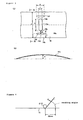
- the slat 16 is formed with a lift cord passing hole 16a through which the lift cord 26 passes.
- the lift cord passing hole 16a requires to be long in a width direction of the slat 16 in order to provide good rotation of the slat 16, that is, to provide a sufficient rotation angle of the slat 16, and therefore, the lift cord passing hole 16a is long in the width direction of the slat 16 and short in a longitudinal direction of the slat 16.
- the slat 16 has a short extension line 16d of the lift cord passing hole 16a (hereinafter simply referred to as an extension line) on a portion formed with the lift cord passing hole 16a, the extension line 16d connecting, in the slat width direction, an edge 16b of the lift cord passing hole 16a in the slat width direction and an edge 16c of the slat 16 in the width direction, and the portion has lower strength than that of other portions, and becomes susceptible to bending along the extension line 16d.
- a rib (protrusion) 16f that protrudes beyond a general plane 16e of the slat 16 is formed near the lift cord passing hole 16a so as to cross the extension line 16d.
- the rib 16f increases rigidity in an out-of-plane direction of the general plane 16e of the slat 16 to prevent it from bending.
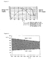
- FIG. 16 is a graph of a relationship between the rotation angle of the slat and presence and absence of the rib.
- the sizes a, b are strictly different between when measured along the general plane 16e and when sizes of projection lines thereof projected on a horizontal plane are measured, but a radius of curvature of the slat 16 is sufficiently large so that the value of b/a is substantially the same when measured by either method, and thus the sizes may be measured by either method.
- the double dotted line in the graph in Figure 5 shows a relationship between the angle through which the slat 16 can rotate and b/a, and shows a maximum angle by which the slat 16 can rotate when the ladder cord support device 17 is operated.
- the dotted line and the solid line in the graph in Figure 5 show relationships between a bending angle of the slat and b/a in the absence and the presence, respectively, of the rib.
- the bending angle of the slat is determined by reading an angle when the slat 16 is rotated around an axis with a projecting side of the general plane 16e facing upward, and the slat 16 is plastically deformed, the axis being the lift cord passing hole 16a (a ⁇ 10 column being the axis), and a point of action being a position 50 mm from the axis.
- the slat 16 is made of aluminum, and is 0.14 ⁇ 0.05 mm thick (except coating), and the rib 16f is 1.5 mm wide, 6 mm long in the longitudinal direction of the slat, and 0.3 mm high, and crosses a midpoint of the extension line 16d.
- the slat crown height e divided by the slat width a is 0.10.
- b/a is preferably in a range from 0.25 to 0.56 as an area where the rotation angle of the slat can be satisfied to a certain degree (approximately 70° or more), and the effect of forming the rib 16f is obtained, that is, an area where the effect differs depending on the presence or the absence of the rib 16f. More preferably, b/a is in a range from 0.25 to 0.54. A value smaller than 0.25 causes no change in the effect depending on the presence or the absence of the rib 16f and provides an insufficient rotation angle of the slat , and a value larger than 0.56 provides a sufficient rotation angle of the slat 16, but the rib 16f provides no effect of increasing the strength.
- the above described desired range of b/a depends on the crown height e.
- a higher crown height e provides higher strength to the entire slat, but provides lower elasticity for restoring the shape of the slat, and the slat becomes susceptible to bending.
- the rotation angle of the slat is also limited.
- a lower crown height provides lower strength to the entire slat, but provides higher elasticity for restoring the shape of the slat, and the slat becomes resistant to buckling. Further, a range of the rotation angle of the slat is increased.
- the desired range (b/a (min) and b/a (max)) of b/a is calculated with the crown height being changed to obtain the results in Table 1.
- Figure 6 is a graph of a range from the formula (1) of the lower limit to the formula (2) of the upper limit. The value of b/a is preferably determined in the range from the lower limit to the upper limit.
- a bending line generally extends on the extension line 16d from the edge 16b of the lift cord passing hole 16a toward the edge 16c of the slat 16, and the rib 16f may cross any position on the extension line 16d of the slat to obtain the effect to a certain degree.
- the rib 16f is far apart from the edge 16b of the lift cord passing hole 16a, the bending line is created between the lift cord passing hole 16a and the rib 16f.
- the rib 16f is excessively near the edge 16c of the slat 16, formability is reduced, and the edge 16c is deformed rather than straight to aesthetic degrade.
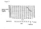
- Figure 7 is a graph of the relationship between the bending angle and the position of the rib 16f, and "c" is a length of the extension line 16d, and “d” is a length from the edge 16b of the lift cord passing hole 16a to a center of the rib.
- the slat 16 is made of aluminum, and the rib 16f is 1.5 mm wide, 6 mm long in the longitudinal direction of the slat, and 0.3 mm high, and b/a is 0.44.
- the bending angle of the slat is measured by the method shown in Figure 4 . It is apparent from the graph in Figure 7 that d/c is preferably in a range from 0 to 0.8 as an area where a strength increasing effect of the slat 16 is obtained, and the aesthetic is not degraded.
- the strength increasing effect can be obtained simply by the rib or the protrusion 16f crossing the extension line 16d, but a length g of the rib 16f is preferably increased correspondingly to a width f of the lift cord passing hole 16a.
- a relationship between the width f of the lift cord passing hole 16a in the longitudinal direction of the slat and the length g of the rib 16f in the longitudinal direction of the slat will be described below.
- Figure 8 shows stress distribution on and around a rib calculated by numerical analysis using a finite-element method, when the length g of the rib 16f is changed with respect to the lift cord passing hole 16a having a constant width, and in each of Figures 8 (a) to 8(i) , an upper side shows a projecting side of the rib, and a lower side shows a recess side of the rib. A dark portion shows high stress, and a light portion shows low stress.
- Figure 8 it is shown that if the length g of the rib 16f is relatively long, that is, g/f is large, the stress concentration is reduced, and if g/f is small, an effect of reducing the stress concentration is small.
- a high stress area extends from the lift cord passing hole 16a to the rib 16f, but in Figure 8 (c) , the high stress area is separately positioned from the lift cord passing hole 16a to the rib 16f.
- g/f is 1.6 or more as in Figure 8 (c) , the bending can be effectively prevented.
- a larger and wider rib 16f can keep the strength more effectively to prevent the bending of the slat, but too high a rib 16f causes the coating of the slat to be stripped.
- a maximum height of the rib 16f is preferably in a range from 0.1 mm to 0.6 mm, more preferably in a range from 0.2 mm to 0.35 mm.
- a root of the rib 16f preferably has a gently curved rise rather than a sharp rise as shown in Figure 10 .
- the curved rise is larger than a rise naturally provided when forming (a radius of curvature of the naturally provided rise is about 0.15 to 0.2 mm), and as shown in Figure 10(b) that shows a cross section of the rib 16f (a section taken along a direction substantially perpendicular to a longitudinal direction of the rib), the root is preferably curved with a radius of curvature R 1 of 0.2 mm or more.
- the entire portion of the rib 16f other than the root is preferably curved with a radius of curvature R 2 of 0.3 mm or more. This prevents stripping of the coating.
- too large a radius of curvature prevents ensuring the above described height of the rib 16f with an appropriate width (a preferable width of about 1 mm to 4 mm) capable of existing within the slat, and thus the curve preferably has a radius of curvature R 2 of 4 mm or less. More preferably, R 2 is in a range from 1 mm to 3 mm.
- one rib 16f crosses each of the two extension line 16d from the both edges 16b of the lift cord passing hole 16a to the both edges 16c of the slat 16, but not limited to this, a rib 16f may be formed on one of the extension lines 16d, or many ribs 16f crossing the extension line 16d may be formed on one extension line 16d.
- a rib 16f may be formed near each of the lift cord passing holes 16a, but an object tends to be caught by longitudinal ends of the slat 16 to often cause bending, thus the rib 16f may be formed near the lift cord passing hole 16a only at the longitudinal both ends of the slat 16.
- the rib or protrusion 16f may be formed into any shape including an arc shape (indicate by 16-1f in Figure 9 ), an inverse arc shape, a circular shape or like, besides the linear shape as shown in Figure 2 .
- a rib in the arc shape (or the inverse arc shape) has large sections in the slat width direction around the both ends, and provides strength against a twisting force of the slat.
- the edge 16b of the lift cord passing hole 16a is in the arc shape, and thus stress may act radially from the edge 16b besides on the extension line 16d, depending on the bending direction of the slat 16, and the arc shaped rib 16-1f allows the both ends of the rib 16-if to approach the edges 16b of the lift cord passing hole 16a, and prevents such radial bending in such a short distance compared to the linear rib 16f.
- the rib is formed to prevent the slats 16 from tightly contacting each other even if the slats 16 overlap, thus preventing the ladder cord 14 from being accidentally passed through two overlapped slats 16 while manufacturing a blind.
- boring of the lift cord passing hole 16a and drawing of the rib 16f may be performed in separate steps, but this increases the number of manufacturing steps and causes displacement between the lift cord passing hole 16a and the rib 16f.
- forming using the forming machine according to the invention allows boring of the lift cord passing hole 16a and drawing of the rib 16f to be performed at the same time.
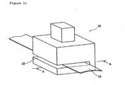
- Figures 11 to 13 show the forming machine.
- the forming machine 30 is formed with a slit 32 into which the slat 16 is inserted.
- the forming machine 30 includes thereinside, as shown in Figure 12 , a first die 34 formed with a recess 34a corresponding to the position of the lift cord passing hole 16a, and a second die 36 formed with a projection 36a for forming the rib 16f, and the first die 34 and the second die 36 constitute a die.
- the recess 34a may be a hole with a bottom or a through hole.
- the second die 36 may be formed integral with the first die 34, but is provided separately to allow replacement of the second die 36 only, even when the width of the slat is changed, and the length between the lift cord passing hole 16a and the rib 16f requires to be changed, or the shape or the size of the rib 16f requires to be changed. If repeated use wears away a top surface of the first die 34, and a top surface of the die requires to be smoothed, a bottom surface of the second die 36 is cut away instead of cutting away a top surface of the second die 36 formed with the projection 36a, thus the top surface of the first die 34 becomes flush with the top surface of the second die 36.
- a punch 38 for boring is provided opposite the recess 34a of the first die 34 so as to be vertically movable, and cushioning materials 40, 40 made of urethane rubber or other materials are provided on both sides of the punch 38.
- the cushioning materials 40 protrude beyond a cutting edge of the punch 38 in a natural state, follow vertical movement of the punch 38, and are elastically displaced vertically with respect to the punch 38 by elasticity thereof.
- the slat 16 is placed between the punch 38 and the first and second dies 34, 36, the punch 38 is pushed into the recess 34a of the first die 34 to form the lift cord passing hole 16a in the slat 16, and at the same time, the projections 36a, 36a formed on the second die 36 are pressed against the cushioning materials 40 with the slat 16 being held therebetween to form the ribs 16f on the slat 16 ( Figure 13 ).
- the lift cord passing hole 16a and the rib 16f can be formed at a time.
- the cushioning material 40 is compressed to press the projecting side of the rib 16f, thus forming the rib 16f having the above described curved rise, and preventing the coating on the surface of the slat 16 from being damaged.
- Figures 14 and 15 show another example of a forming machine 30, and instead of the cushioning material 40 such as urethane rubber, cushioning holders 44 connected via springs 46 are provided around a punch 38, and the cushioning holders 44 are elastically displaced vertically with respect to the punch 38 by the springs 46.
- the punch 38 is pushed into the recess 34a of the first die 34 to form the lift cord passing hole 16a in the slat 16, and at the same time, the projections 36a, 36a formed on the second die 36 are pressed against the cushioning holders 44 with the slat 16 being held therebetween to form the ribs 16f on the slat 16.
- the cushioning holder 44 compresses the spring 46 to press the projecting side of the rib 16f, thus forming the rib 16f having the above described curved rise, and preventing the coating on the surface of the slat 16 from being damaged.
- the invention provides a strength increasing effect by forming a rib with keeping good rotation of a slat.
Landscapes
- Engineering & Computer Science (AREA)
- Structural Engineering (AREA)
- Architecture (AREA)
- Civil Engineering (AREA)
- Blinds (AREA)
- Details Of Garments (AREA)
- Stored Programmes (AREA)
- Peptides Or Proteins (AREA)
- Dry Formation Of Fiberboard And The Like (AREA)
- Rolls And Other Rotary Bodies (AREA)
- Bending Of Plates, Rods, And Pipes (AREA)
Claims (19)
- Jalousie (10), bei der zahlreiche Lamellen (16) in Flucht von einer Leiterschnur (14) getragen sind, die von einem Oberkasten (12) herabhängt, ein oberes Ende der Leiterschnur (14) von einer Leiterschnur-Tragevorrichtung (17) getragen ist, die sich im Oberkasten (12) befindet, die Leiterschnur-Tragevorrichtung (17) betätigt wird, um die Lamellen (16) zu drehen, ein Ende einer Hebeschnur (26) mit einer unteren Schiene (24) verbunden ist, die sich an der Unterseite einer Reihe von Lamellen (16) befindet und mit der ein unteres Ende der Leiterschnur (14) verbunden ist, während das andere Ende der Hebeschnur (26) durch die Reihe von Lamellen (16) verläuft und in den Oberkasten (12) eingeführt ist, und die Hebeschnur (26) angezogen oder abgelassen wird, um die Reihe von Lamellen (16) und die untere Schiene (24) anzuheben oder abzusenken, wobei
die Lamelle (16) mit einem Hebeschnur-Durchgangsloch (16a) ausgebildet ist, durch das die Hebeschnur verläuft, wobei die Lamelle (16) eine sanft gewölbte Gesamtfläche (16e) hat, dadurch gekennzeichnet, dass sich die Scheitelhöhe im Bereich des Hebeschnur-Durchgangsloches (16a) befindet, und wenn eine Länge des Hebeschnur-Durchgangsloches (16a) in einer Lamellenbreitenrichtung b ist, eine Lamellenbreite a ist und eine Lamellen-Scheitelhöhe e ist,
- Jalousie (10) nach Anspruch 1, dadurch gekennzeichnet, dass der Vorsprung (16f) der Lamelle (16) derart angeordnet ist, dass, wenn eine Länge in der Lamellenbreitenrichtung vom Rand (16b) des Hebeschnur-Durchgangsloches (16a) in der Lamellenbreitenrichtung zum Rand (16c) der Lamelle (16) in der Lamellenbreitenrichtung c ist und eine Länge in der Lamellenbreitenrichtung vom Rand (16b) des Hebeschnur-Durchgangsloches (16a) in der Lamellenbreitenrichtung zu einem Schnittpunkt zwischen der Erweiterungslinie (16d) und dem Vorsprung (16f) d ist, ein Bereich von 0 ≤ d/c ≤ 0,8 erfüllt ist.
- Jalousie (10) nach Anspruch 1 oder 2, dadurch gekennzeichnet, dass, wenn eine Breite des Hebeschnur-Durchgangsloches (16a) in einer Längsrichtung der Lamelle (16) f ist und eine Länge des Vorsprungs (16f) der Lamelle (16) in der Längsrichtung der Lamelle (16) g ist, g/f ≤ 1,6 erfüllt ist.
- Jalousie (10) nach einem der Ansprüche 1 bis 3, dadurch gekennzeichnet, dass eine Maximalhöhe des Vorsprungs (16f) der Lamelle (16) im Bereich von 0,1 mm bis 0,6 mm liegt.
- Jalousie (10) nach einem der Ansprüche 1 bis 4, dadurch gekennzeichnet, dass sich ein Ursprung des Vorsprungs (16f) sanft von der leicht gewölbten Gesamtfläche (16f) erhebt, um eine Wölbung zu bilden.
- Jalousie (10) nach einem der Ansprüche 1 bis 5, dadurch gekennzeichnet, dass eine Vorsprungsfläche des Vorsprungs (16f) der Lamelle (16) einen Wölbungsradius in einem Bereich von 0,3 mm bis 4 mm hat.
- Jalousie (10) nach einem der Ansprüche 1 bis 6, dadurch gekennzeichnet, dass sich der Vorsprung (16f) der Lamelle (16) linear parallel zur Längsrichtung der Lamelle (16) erstreckt.
- Jalousie (10) nach einem der Ansprüche 1 bis 6, dadurch gekennzeichnet, dass sich der Vorsprung (16f) der Lamelle derart erstreckt, dass er einen Bogen ausbildet, der den Rand (16b) des Hebeschnur-Durchgangsloches umgibt.
- Jalousielamelle (16), ausgebildet mit einem Hebeschnur-Durchgangsloch (16a), durch das eine Hebeschnur (28) zum Anheben und Absenken einer Jalousie (10) verläuft, wobei die Lamelle (16) eine sanft gewölbte Gesamtfläche (16e) hat, dadurch gekennzeichnet, dass sich die Lamellen-Scheitelhöhe im Bereich des Hebeschnur-Durchgangsloches (16a) befindet, und wenn eine Länge des Hebeschnur-Durchgangsloches (16a) in einer Lamellenbreitenrichtung b ist, eine Lamellenbreite a ist und eine Lamellenscheitelhöhe e ist,

- Jalousielamelle (16) nach Anspruch 9, dadurch gekennzeichnet, dass der Vorsprung (16f) der Lamelle (16) derart angeordnet ist, dass, wenn eine Länge in der Lamellenbreitenrichtung vom Rand (16b) des Hebeschnur-Durchgangsloches (16a) in der Lamellenbreitenrichtung zum Rand (16c) der Lamelle (16) in der Lamellenbreitenrichtung c ist und eine Länge in der Lamellenbreitenrichtung vom Rand (16b) des Hebeschnur-Durchgangsloches (16a) in der Lamellenbreitenrichtung zu einem Schnittpunkt zwischen der Erweiterungslinie (16d) und dem Vorsprung (16f) d ist, ein Bereich von 0 ≤ d/c ≤ 0,8 erfüllt ist.
- Jalousielamelle (16) nach Anspruch 9 oder 10, dadurch gekennzeichnet, dass, wenn eine Breite des Hebeschnur-Durchgangsloches (16a) in einer Längsrichtung der Lamelle (16) f ist und eine Länge des Vorsprungs (16f) der Lamelle (16) in der Längsrichtung der Lamelle (16) g ist, g/f ≤ 1,6 erfüllt ist.
- Jalousielamelle (16) nach einem der Ansprüche 9 bis 11, dadurch gekennzeichnet, dass eine Maximalhöhe des Vorsprungs (16f) der Lamelle (16) im Bereich von 0,1 mm bis 0,6 mm liegt.
- Jalousielamelle (16) nach einem der Ansprüche 9 bis 12, dadurch gekennzeichnet, dass sich ein Ursprung des Vorsprungs (16f) sanft von der leicht gewölbten Gesamtfläche (16f) erhebt, um eine Wölbung zu bilden.
- Jalousielamelle (16) nach einem der Ansprüche 9 bis 13, dadurch gekennzeichnet, dass eine Vorsprungsfläche des Vorsprungs (16f) der Lamelle (16) einen Wölbungsradius in einem Bereich von 0,3 mm bis 4 mm hat.
- Jalousielamelle (16) nach einem der Ansprüche 9 bis 14, dadurch gekennzeichnet, dass sich der Vorsprung (16f) der Lamelle (16) linear parallel zur Längsrichtung der Lamelle (16) erstreckt.
- Jalousielamelle (16) nach einem der Ansprüche 9 bis 14, dadurch gekennzeichnet, dass sich der Vorsprung (16f) der Lamelle derart erstreckt, dass er einen Bogen ausbildet, der den Rand (16b) des Hebeschnur-Durchgangsloches umgibt.
- Herstellungsverfahren für eine Jalousielamelle (16), dadurch gekennzeichnet, dass eine Lamelle (16) gemäß einem der Ansprüche 9 bis 16 mit einem Hebeschnur-Durchgangsloch (16a) ausgebildet wird, wobei
das Hebeschnur-Durchgangsloch (16a) und der Vorsprung (16f) gleichzeitig ausgebildet werden. - Fertigungsmaschine (30) für eine Lamelle (16) zum Ausbilden eines Hebeschnur-Durchgangsloches (16a) in der Lamelle (16) gemäß einem der Ansprüche 9 bis 16, enthaltend:ein Gesenk, das mit einer Aussparung (34a) an einer Stelle entsprechend dem Hebeschnur-Durchgangsloch (16a) ausgebildet ist und mit einem Vorsprung (36a) an einer Stelle entsprechend dem Vorsprung (16f) versehen ist;einen Stempel (38) der gegenüberliegend zur Aussparung (34a) vertikal bewegt werden kann; undeinen Dämpfungsabschnitt (40), der gegenüberliegend dem Vorsprung, dem Stempel folgend, vertikal bewegt werden kann und im Bezug auf den Stempel (38) vertikal verformbar verschoben werden kann.
- Fertigungsmaschine (30) nach Anspruch 18, bei der das Gesenk ein erstes Gesenk (34), das mit der Aussparung (34a) versehen ist, und ein zweites Gesenk (36), getrennt vom ersten Gesenk (34), enthält, dass mit dem Vorsprung (36a) ausgebildet ist.
Applications Claiming Priority (5)
| Application Number | Priority Date | Filing Date | Title |
|---|---|---|---|
| JP2001079802 | 2001-03-21 | ||
| JP2001079802 | 2001-03-21 | ||
| JP2001244560 | 2001-08-10 | ||
| JP2001244560A JP3475186B2 (ja) | 2001-03-21 | 2001-08-10 | ブラインド、ブラインド用スラット、その製造方法及びその成形加工機 |
| PCT/JP2002/002596 WO2002075096A1 (en) | 2001-03-21 | 2002-03-19 | Blind, slat for blinds, and method of producing the same and forming machine therefor |
Publications (3)
| Publication Number | Publication Date |
|---|---|
| EP1371809A1 EP1371809A1 (de) | 2003-12-17 |
| EP1371809A4 EP1371809A4 (de) | 2004-06-16 |
| EP1371809B1 true EP1371809B1 (de) | 2008-10-15 |
Family
ID=26611626
Family Applications (1)
| Application Number | Title | Priority Date | Filing Date |
|---|---|---|---|
| EP02705336A Expired - Lifetime EP1371809B1 (de) | 2001-03-21 | 2002-03-19 | "jalousie, lamelle für jalousien und verfahren zur herstellung derselben und herstellungsmaschine dafür" |
Country Status (8)
| Country | Link |
|---|---|
| US (2) | US7069973B2 (de) |
| EP (1) | EP1371809B1 (de) |
| JP (1) | JP3475186B2 (de) |
| AT (1) | ATE411445T1 (de) |
| AU (1) | AU2002238966B2 (de) |
| BR (1) | BR0208213B1 (de) |
| DE (1) | DE60229362D1 (de) |
| WO (1) | WO2002075096A1 (de) |
Families Citing this family (8)
| Publication number | Priority date | Publication date | Assignee | Title |
|---|---|---|---|---|
| JP3475186B2 (ja) | 2001-03-21 | 2003-12-08 | 株式会社ニチベイ | ブラインド、ブラインド用スラット、その製造方法及びその成形加工機 |
| US20080196310A1 (en) * | 2007-02-19 | 2008-08-21 | Ruizhong Wang | Window shutter |
| US20100206491A1 (en) * | 2009-02-13 | 2010-08-19 | Taihao Knitting Belt Co., Ltd. | Venetian blind with a thin profile latticed strip |
| US20120227917A1 (en) * | 2011-03-07 | 2012-09-13 | Ching Feng Home Fashions Co., Ltd. | Hollow slat |
| US9266159B2 (en) | 2011-08-02 | 2016-02-23 | Chad Wooters | Venetian blind repair tool |
| TWM527914U (zh) * | 2016-04-25 | 2016-09-01 | Ching Feng Home Fashions Co | 簾體安全繫繩構造 |
| TWI796176B (zh) * | 2022-03-22 | 2023-03-11 | 型態同步科技股份有限公司 | 百葉窗簾及百葉窗簾的葉片 |
| CN116146092A (zh) * | 2023-04-19 | 2023-05-23 | 汉狮光动科技(广东)有限公司 | 一种高遮蔽性的帘片及一种遮帘 |
Family Cites Families (51)
| Publication number | Priority date | Publication date | Assignee | Title |
|---|---|---|---|---|
| US2603286A (en) * | 1952-07-15 | Venetian blind slat | ||
| US2315640A (en) * | 1936-11-18 | 1943-04-06 | Acme Steel Co | Venetian blind slat |
| US2262550A (en) * | 1937-11-23 | 1941-11-11 | Joseph L Hunter | Means for producing venetian blind slats |
| US2176259A (en) * | 1938-05-13 | 1939-10-17 | Charles M Guy | Venetian blind |
| US2789639A (en) * | 1950-09-09 | 1957-04-23 | Lorentzen Hardware Mfg Corp | Method useful in the manufacture of venetian blinds |
| CH331142A (it) * | 1954-10-04 | 1958-07-15 | Vedetta S R L | Tenda del tipo detto "alla Veneziana" |
| US2886069A (en) * | 1956-08-02 | 1959-05-12 | Artcraft Venetian Blind Mfg Co | Machine for making slatted material |
| JPS5820792Y2 (ja) * | 1978-04-22 | 1983-04-30 | ト−ソ−株式会社 | ブラインドのスラツト補修板 |
| JPS5938187B2 (ja) | 1981-01-30 | 1984-09-14 | 日立電線株式会社 | 3−5族化合物半導体単結晶の製造方法 |
| JPS57129899U (de) * | 1981-02-09 | 1982-08-13 | ||
| JPS5820792A (ja) | 1981-07-24 | 1983-02-07 | 中神 征史 | 直立塔型堆肥化装置 |
| SE441941B (sv) * | 1984-04-13 | 1985-11-18 | Berndt Roland Nilsson | Persienntillverkningsmaskin |
| US4639987A (en) * | 1985-04-19 | 1987-02-03 | Levolor Lorentzen, Inc. | Apparatus for producing simultaneously a plurality of Venetian blinds |
| JPS62131096A (ja) | 1985-12-02 | 1987-06-13 | Ishikawajima Harima Heavy Ind Co Ltd | 石炭−液体スラリの貯蔵輸送方法 |
| JPS62260984A (ja) * | 1986-04-25 | 1987-11-13 | 株式会社ニチベイ | ブラインド用スラツト |
| US4799526A (en) * | 1986-06-27 | 1989-01-24 | Wausau Metals Corporation | Blind with light-transmitting slats |
| EP0295346B1 (de) * | 1987-06-18 | 1991-05-15 | Hunter Douglas Industries B.V. | Verfahren und Vorrichtung zur mechanischen Herstellung von Jalousien |
| JPH0710759B2 (ja) | 1990-05-10 | 1995-02-08 | 工業技術院長 | 酸化物系超伝導膜の製造方法 |
| AU1457892A (en) * | 1991-04-08 | 1992-11-02 | Ronald W.E. Ingram | Method and apparatus for the manufacture of blinds |
| US5176193A (en) * | 1991-04-09 | 1993-01-05 | Levolor Corporation | Venetian blind slat construction |
| SE468401B (sv) * | 1991-05-08 | 1993-01-11 | Sani Maskiner Ab | Persienntillverkningsmaskin samt stansanordning foer denna |
| US5504891A (en) * | 1991-10-17 | 1996-04-02 | Ricoh Company, Ltd. | Method and apparatus for format conversion of a hierarchically structured page description language document |
| US5349730A (en) * | 1993-03-09 | 1994-09-27 | Hunter Douglas Inc. | Mehtod and apparatus for assembling blinds |
| US5573054A (en) * | 1995-01-12 | 1996-11-12 | Springs Window Fashions Division, Inc. | Venetian blind slat |
| JPH08227415A (ja) * | 1995-02-21 | 1996-09-03 | Fuji Xerox Co Ltd | 文書編集装置 |
| US5781914A (en) * | 1995-06-30 | 1998-07-14 | Ricoh Company, Ltd. | Converting documents, with links to other electronic information, between hardcopy and electronic formats |
| US5745360A (en) * | 1995-08-14 | 1998-04-28 | International Business Machines Corp. | Dynamic hypertext link converter system and process |
| US6055522A (en) * | 1996-01-29 | 2000-04-25 | Futuretense, Inc. | Automatic page converter for dynamic content distributed publishing system |
| US5745908A (en) * | 1996-03-29 | 1998-04-28 | Systems Focus International | Method for converting a word processing file containing markup language tags and conventional computer code |
| US5804803A (en) * | 1996-04-02 | 1998-09-08 | International Business Machines Corporation | Mechanism for retrieving information using data encoded on an object |
| US6003046A (en) * | 1996-04-15 | 1999-12-14 | Sun Microsystems, Inc. | Automatic development and display of context information in structured documents on the world wide web |
| US5848386A (en) * | 1996-05-28 | 1998-12-08 | Ricoh Company, Ltd. | Method and system for translating documents using different translation resources for different portions of the documents |
| EP0810533B1 (de) * | 1996-05-29 | 2002-04-10 | Matsushita Electric Industrial Co., Ltd. | Anordnung zur Dokumentkonvertierung |
| JP3352462B2 (ja) * | 1996-07-03 | 2002-12-03 | インターナシヨナル・ビジネス・マシーンズ・コーポレーシヨン | 損失補償手段を備えた機械式信号プロセッサ |
| US5911145A (en) * | 1996-07-29 | 1999-06-08 | Rae Technology, Inc. | Hierarchical structure editor for web sites |
| US5845299A (en) * | 1996-07-29 | 1998-12-01 | Rae Technology Llc | Draw-based editor for web pages |
| WO1998006033A1 (en) * | 1996-08-08 | 1998-02-12 | Agranat Systems, Inc. | Embedded web server |
| SG70025A1 (en) * | 1996-08-14 | 2000-01-25 | Nippon Telegraph & Telephone | Method and system for preparing and registering homepages interactive input apparatus for multimedia informations and recording medium including interactive input programs of the multimedia informations |
| US5895477A (en) * | 1996-09-09 | 1999-04-20 | Design Intelligence, Inc. | Design engine for automatic layout of content |
| US5956737A (en) * | 1996-09-09 | 1999-09-21 | Design Intelligence, Inc. | Design engine for fitting content to a medium |
| US6061697A (en) * | 1996-09-11 | 2000-05-09 | Fujitsu Limited | SGML type document managing apparatus and managing method |
| US5956736A (en) * | 1996-09-27 | 1999-09-21 | Apple Computer, Inc. | Object-oriented editor for creating world wide web documents |
| US5909214A (en) * | 1996-11-04 | 1999-06-01 | International Business Machines Corp. | Method and system for drop guides for visual layout in Java layout managers |
| US5893127A (en) * | 1996-11-18 | 1999-04-06 | Canon Information Systems, Inc. | Generator for document with HTML tagged table having data elements which preserve layout relationships of information in bitmap image of original document |
| US6144974A (en) * | 1996-12-13 | 2000-11-07 | Adobe Systems Incorporated | Automated layout of content in a page framework |
| US5940834A (en) * | 1997-03-13 | 1999-08-17 | Mitel Corporation | Automatic web page generator |
| US6023714A (en) * | 1997-04-24 | 2000-02-08 | Microsoft Corporation | Method and system for dynamically adapting the layout of a document to an output device |
| US6026417A (en) * | 1997-05-02 | 2000-02-15 | Microsoft Corporation | Desktop publishing software for automatically changing the layout of content-filled documents |
| US6002874A (en) * | 1997-12-22 | 1999-12-14 | International Business Machines Corporation | Method and system for translating goto-oriented procedural languages into goto-free object oriented languages |
| US6072486A (en) * | 1998-01-13 | 2000-06-06 | Microsoft Corporation | System and method for creating and customizing a deskbar |
| JP3475186B2 (ja) | 2001-03-21 | 2003-12-08 | 株式会社ニチベイ | ブラインド、ブラインド用スラット、その製造方法及びその成形加工機 |
-
2001
- 2001-08-10 JP JP2001244560A patent/JP3475186B2/ja not_active Expired - Lifetime
-
2002
- 2002-03-19 AU AU2002238966A patent/AU2002238966B2/en not_active Ceased
- 2002-03-19 AT AT02705336T patent/ATE411445T1/de not_active IP Right Cessation
- 2002-03-19 DE DE60229362T patent/DE60229362D1/de not_active Expired - Lifetime
- 2002-03-19 BR BRPI0208213-6A patent/BR0208213B1/pt not_active IP Right Cessation
- 2002-03-19 WO PCT/JP2002/002596 patent/WO2002075096A1/ja not_active Ceased
- 2002-03-19 US US10/472,235 patent/US7069973B2/en not_active Expired - Fee Related
- 2002-03-19 EP EP02705336A patent/EP1371809B1/de not_active Expired - Lifetime
-
2005
- 2005-05-25 US US11/136,486 patent/US7461440B2/en not_active Expired - Fee Related
Also Published As
| Publication number | Publication date |
|---|---|
| JP2002349161A (ja) | 2002-12-04 |
| AU2002238966B2 (en) | 2005-10-06 |
| ATE411445T1 (de) | 2008-10-15 |
| BR0208213A (pt) | 2004-03-09 |
| EP1371809A4 (de) | 2004-06-16 |
| US20050269042A1 (en) | 2005-12-08 |
| JP3475186B2 (ja) | 2003-12-08 |
| US7069973B2 (en) | 2006-07-04 |
| WO2002075096A1 (en) | 2002-09-26 |
| BR0208213B1 (pt) | 2011-12-13 |
| DE60229362D1 (de) | 2008-11-27 |
| US20040089427A1 (en) | 2004-05-13 |
| US7461440B2 (en) | 2008-12-09 |
| EP1371809A1 (de) | 2003-12-17 |
Similar Documents
| Publication | Publication Date | Title |
|---|---|---|
| US6782788B1 (en) | Cutting blade for a cutting apparatus | |
| AU2002238966B2 (en) | Blind, slat for blinds, and method of producing the same and forming machine therefor | |
| US8464620B2 (en) | Hole punch element | |
| US6314851B1 (en) | Dual mini-blind cutter | |
| US11208841B2 (en) | Slats with an improved route hole configuration for use within a covering and related manufacturing methods | |
| US5730038A (en) | Configuration for paper punch pin | |
| US6095228A (en) | Tilt rod support for a venetian blind | |
| US8739666B2 (en) | Window covering cutting machine | |
| US5238043A (en) | Apparatus for accurate adjustment of the slats in a venetian blind | |
| KR200355700Y1 (ko) | 음식물 랩 커터 | |
| US4611520A (en) | Punching unit in a punching and/or binding machine for joining together a pack of sheets by a comb binder | |
| US5176193A (en) | Venetian blind slat construction | |
| KR100392926B1 (ko) | 자 | |
| EP0483044A2 (de) | Biegemaschine | |
| US10478987B1 (en) | Cutting module of cutting machine for window covering | |
| EP3677360A1 (de) | Federherstellungsmaschine | |
| DE9411372U1 (de) | Lamelle für Lamellenjalousien | |
| KR200295484Y1 (ko) | 업컷시어절단시편뒤틀림방지장치 | |
| WO2012112083A1 (en) | Vehicle door and method for mounting a window glass in a vehicle door | |
| KR200364470Y1 (ko) | 철망용 와이어 절단장치 | |
| EP2140148B1 (de) | Verfahren zur befestigung eines abschirmkörpers an einem unteren element in einer abschirmanordnung | |
| KR102400938B1 (ko) | 슬랫 각도 조절기 및 이를 포함하는 블라인드 장치 | |
| WO2024117966A1 (en) | A device for resizing a window covering arrangement | |
| AU2019201868B2 (en) | Cutting module of cutting machine for window covering | |
| JP3102791U (ja) | ベネシャンブラインドのスラット |
Legal Events
| Date | Code | Title | Description |
|---|---|---|---|
| PUAI | Public reference made under article 153(3) epc to a published international application that has entered the european phase |
Free format text: ORIGINAL CODE: 0009012 |
|
| 17P | Request for examination filed |
Effective date: 20031007 |
|
| AK | Designated contracting states |
Kind code of ref document: A1 Designated state(s): AT BE CH DE DK FI FR GB IT LI NL SE |
|
| A4 | Supplementary search report drawn up and despatched |
Effective date: 20040507 |
|
| RIC1 | Information provided on ipc code assigned before grant |
Ipc: 7E 06B 9/266 B Ipc: 7E 06B 9/386 A |
|
| GRAP | Despatch of communication of intention to grant a patent |
Free format text: ORIGINAL CODE: EPIDOSNIGR1 |
|
| GRAS | Grant fee paid |
Free format text: ORIGINAL CODE: EPIDOSNIGR3 |
|
| GRAA | (expected) grant |
Free format text: ORIGINAL CODE: 0009210 |
|
| AK | Designated contracting states |
Kind code of ref document: B1 Designated state(s): AT BE CH DE DK FI FR GB IT LI NL SE |
|
| REG | Reference to a national code |
Ref country code: CH Ref legal event code: EP Ref country code: GB Ref legal event code: FG4D |
|
| REF | Corresponds to: |
Ref document number: 60229362 Country of ref document: DE Date of ref document: 20081127 Kind code of ref document: P |
|
| REG | Reference to a national code |
Ref country code: SE Ref legal event code: TRGR |
|
| PG25 | Lapsed in a contracting state [announced via postgrant information from national office to epo] |
Ref country code: AT Free format text: LAPSE BECAUSE OF FAILURE TO SUBMIT A TRANSLATION OF THE DESCRIPTION OR TO PAY THE FEE WITHIN THE PRESCRIBED TIME-LIMIT Effective date: 20081015 |
|
| PG25 | Lapsed in a contracting state [announced via postgrant information from national office to epo] |
Ref country code: FI Free format text: LAPSE BECAUSE OF FAILURE TO SUBMIT A TRANSLATION OF THE DESCRIPTION OR TO PAY THE FEE WITHIN THE PRESCRIBED TIME-LIMIT Effective date: 20081015 |
|
| PG25 | Lapsed in a contracting state [announced via postgrant information from national office to epo] |
Ref country code: DK Free format text: LAPSE BECAUSE OF FAILURE TO SUBMIT A TRANSLATION OF THE DESCRIPTION OR TO PAY THE FEE WITHIN THE PRESCRIBED TIME-LIMIT Effective date: 20081015 Ref country code: BE Free format text: LAPSE BECAUSE OF FAILURE TO SUBMIT A TRANSLATION OF THE DESCRIPTION OR TO PAY THE FEE WITHIN THE PRESCRIBED TIME-LIMIT Effective date: 20081015 |
|
| PLBE | No opposition filed within time limit |
Free format text: ORIGINAL CODE: 0009261 |
|
| STAA | Information on the status of an ep patent application or granted ep patent |
Free format text: STATUS: NO OPPOSITION FILED WITHIN TIME LIMIT |
|
| 26N | No opposition filed |
Effective date: 20090716 |
|
| REG | Reference to a national code |
Ref country code: CH Ref legal event code: PL |
|
| REG | Reference to a national code |
Ref country code: FR Ref legal event code: ST Effective date: 20091130 |
|
| PG25 | Lapsed in a contracting state [announced via postgrant information from national office to epo] |
Ref country code: CH Free format text: LAPSE BECAUSE OF NON-PAYMENT OF DUE FEES Effective date: 20090331 Ref country code: LI Free format text: LAPSE BECAUSE OF NON-PAYMENT OF DUE FEES Effective date: 20090331 |
|
| PG25 | Lapsed in a contracting state [announced via postgrant information from national office to epo] |
Ref country code: FR Free format text: LAPSE BECAUSE OF NON-PAYMENT OF DUE FEES Effective date: 20091123 |
|
| PGFP | Annual fee paid to national office [announced via postgrant information from national office to epo] |
Ref country code: DE Payment date: 20170314 Year of fee payment: 16 Ref country code: SE Payment date: 20170313 Year of fee payment: 16 Ref country code: NL Payment date: 20170320 Year of fee payment: 16 |
|
| PGFP | Annual fee paid to national office [announced via postgrant information from national office to epo] |
Ref country code: GB Payment date: 20170315 Year of fee payment: 16 |
|
| PGFP | Annual fee paid to national office [announced via postgrant information from national office to epo] |
Ref country code: IT Payment date: 20170320 Year of fee payment: 16 |
|
| REG | Reference to a national code |
Ref country code: DE Ref legal event code: R119 Ref document number: 60229362 Country of ref document: DE |
|
| PG25 | Lapsed in a contracting state [announced via postgrant information from national office to epo] |
Ref country code: SE Free format text: LAPSE BECAUSE OF NON-PAYMENT OF DUE FEES Effective date: 20180320 |
|
| REG | Reference to a national code |
Ref country code: NL Ref legal event code: MM Effective date: 20180401 |
|
| GBPC | Gb: european patent ceased through non-payment of renewal fee |
Effective date: 20180319 |
|
| PG25 | Lapsed in a contracting state [announced via postgrant information from national office to epo] |
Ref country code: NL Free format text: LAPSE BECAUSE OF NON-PAYMENT OF DUE FEES Effective date: 20180401 |
|
| PG25 | Lapsed in a contracting state [announced via postgrant information from national office to epo] |
Ref country code: DE Free format text: LAPSE BECAUSE OF NON-PAYMENT OF DUE FEES Effective date: 20181002 |
|
| PG25 | Lapsed in a contracting state [announced via postgrant information from national office to epo] |
Ref country code: GB Free format text: LAPSE BECAUSE OF NON-PAYMENT OF DUE FEES Effective date: 20180319 Ref country code: IT Free format text: LAPSE BECAUSE OF NON-PAYMENT OF DUE FEES Effective date: 20180319 |