EP1369705A1 - Signal processing method for scanning radar - Google Patents
Signal processing method for scanning radar Download PDFInfo
- Publication number
- EP1369705A1 EP1369705A1 EP02705274A EP02705274A EP1369705A1 EP 1369705 A1 EP1369705 A1 EP 1369705A1 EP 02705274 A EP02705274 A EP 02705274A EP 02705274 A EP02705274 A EP 02705274A EP 1369705 A1 EP1369705 A1 EP 1369705A1
- Authority
- EP
- European Patent Office
- Prior art keywords
- peaks
- target
- angle
- peak
- radar
- Prior art date
- Legal status (The legal status is an assumption and is not a legal conclusion. Google has not performed a legal analysis and makes no representation as to the accuracy of the status listed.)
- Granted
Links
Images






Classifications
-
- G—PHYSICS
- G01—MEASURING; TESTING
- G01S—RADIO DIRECTION-FINDING; RADIO NAVIGATION; DETERMINING DISTANCE OR VELOCITY BY USE OF RADIO WAVES; LOCATING OR PRESENCE-DETECTING BY USE OF THE REFLECTION OR RERADIATION OF RADIO WAVES; ANALOGOUS ARRANGEMENTS USING OTHER WAVES
- G01S13/00—Systems using the reflection or reradiation of radio waves, e.g. radar systems; Analogous systems using reflection or reradiation of waves whose nature or wavelength is irrelevant or unspecified
- G01S13/02—Systems using reflection of radio waves, e.g. primary radar systems; Analogous systems
- G01S13/06—Systems determining position data of a target
- G01S13/46—Indirect determination of position data
- G01S13/48—Indirect determination of position data using multiple beams at emission or reception
-
- G—PHYSICS
- G01—MEASURING; TESTING
- G01S—RADIO DIRECTION-FINDING; RADIO NAVIGATION; DETERMINING DISTANCE OR VELOCITY BY USE OF RADIO WAVES; LOCATING OR PRESENCE-DETECTING BY USE OF THE REFLECTION OR RERADIATION OF RADIO WAVES; ANALOGOUS ARRANGEMENTS USING OTHER WAVES
- G01S7/00—Details of systems according to groups G01S13/00, G01S15/00, G01S17/00
- G01S7/02—Details of systems according to groups G01S13/00, G01S15/00, G01S17/00 of systems according to group G01S13/00
- G01S7/28—Details of pulse systems
- G01S7/285—Receivers
- G01S7/292—Extracting wanted echo-signals
-
- G—PHYSICS
- G01—MEASURING; TESTING
- G01S—RADIO DIRECTION-FINDING; RADIO NAVIGATION; DETERMINING DISTANCE OR VELOCITY BY USE OF RADIO WAVES; LOCATING OR PRESENCE-DETECTING BY USE OF THE REFLECTION OR RERADIATION OF RADIO WAVES; ANALOGOUS ARRANGEMENTS USING OTHER WAVES
- G01S13/00—Systems using the reflection or reradiation of radio waves, e.g. radar systems; Analogous systems using reflection or reradiation of waves whose nature or wavelength is irrelevant or unspecified
- G01S13/02—Systems using reflection of radio waves, e.g. primary radar systems; Analogous systems
- G01S13/06—Systems determining position data of a target
- G01S13/08—Systems for measuring distance only
- G01S13/32—Systems for measuring distance only using transmission of continuous waves, whether amplitude-, frequency-, or phase-modulated, or unmodulated
- G01S13/34—Systems for measuring distance only using transmission of continuous waves, whether amplitude-, frequency-, or phase-modulated, or unmodulated using transmission of continuous, frequency-modulated waves while heterodyning the received signal, or a signal derived therefrom, with a locally-generated signal related to the contemporaneously transmitted signal
- G01S13/345—Systems for measuring distance only using transmission of continuous waves, whether amplitude-, frequency-, or phase-modulated, or unmodulated using transmission of continuous, frequency-modulated waves while heterodyning the received signal, or a signal derived therefrom, with a locally-generated signal related to the contemporaneously transmitted signal using triangular modulation
-
- G—PHYSICS
- G01—MEASURING; TESTING
- G01S—RADIO DIRECTION-FINDING; RADIO NAVIGATION; DETERMINING DISTANCE OR VELOCITY BY USE OF RADIO WAVES; LOCATING OR PRESENCE-DETECTING BY USE OF THE REFLECTION OR RERADIATION OF RADIO WAVES; ANALOGOUS ARRANGEMENTS USING OTHER WAVES
- G01S13/00—Systems using the reflection or reradiation of radio waves, e.g. radar systems; Analogous systems using reflection or reradiation of waves whose nature or wavelength is irrelevant or unspecified
- G01S13/02—Systems using reflection of radio waves, e.g. primary radar systems; Analogous systems
- G01S13/06—Systems determining position data of a target
- G01S13/42—Simultaneous measurement of distance and other co-ordinates
-
- G—PHYSICS
- G01—MEASURING; TESTING
- G01S—RADIO DIRECTION-FINDING; RADIO NAVIGATION; DETERMINING DISTANCE OR VELOCITY BY USE OF RADIO WAVES; LOCATING OR PRESENCE-DETECTING BY USE OF THE REFLECTION OR RERADIATION OF RADIO WAVES; ANALOGOUS ARRANGEMENTS USING OTHER WAVES
- G01S13/00—Systems using the reflection or reradiation of radio waves, e.g. radar systems; Analogous systems using reflection or reradiation of waves whose nature or wavelength is irrelevant or unspecified
- G01S13/88—Radar or analogous systems specially adapted for specific applications
- G01S13/93—Radar or analogous systems specially adapted for specific applications for anti-collision purposes
- G01S13/931—Radar or analogous systems specially adapted for specific applications for anti-collision purposes of land vehicles
-
- G—PHYSICS
- G01—MEASURING; TESTING
- G01S—RADIO DIRECTION-FINDING; RADIO NAVIGATION; DETERMINING DISTANCE OR VELOCITY BY USE OF RADIO WAVES; LOCATING OR PRESENCE-DETECTING BY USE OF THE REFLECTION OR RERADIATION OF RADIO WAVES; ANALOGOUS ARRANGEMENTS USING OTHER WAVES
- G01S13/00—Systems using the reflection or reradiation of radio waves, e.g. radar systems; Analogous systems using reflection or reradiation of waves whose nature or wavelength is irrelevant or unspecified
- G01S13/02—Systems using reflection of radio waves, e.g. primary radar systems; Analogous systems
- G01S13/06—Systems determining position data of a target
- G01S13/42—Simultaneous measurement of distance and other co-ordinates
- G01S13/422—Simultaneous measurement of distance and other co-ordinates sequential lobing, e.g. conical scan
-
- G—PHYSICS
- G01—MEASURING; TESTING
- G01S—RADIO DIRECTION-FINDING; RADIO NAVIGATION; DETERMINING DISTANCE OR VELOCITY BY USE OF RADIO WAVES; LOCATING OR PRESENCE-DETECTING BY USE OF THE REFLECTION OR RERADIATION OF RADIO WAVES; ANALOGOUS ARRANGEMENTS USING OTHER WAVES
- G01S13/00—Systems using the reflection or reradiation of radio waves, e.g. radar systems; Analogous systems using reflection or reradiation of waves whose nature or wavelength is irrelevant or unspecified
- G01S13/02—Systems using reflection of radio waves, e.g. primary radar systems; Analogous systems
- G01S13/50—Systems of measurement based on relative movement of target
- G01S13/58—Velocity or trajectory determination systems; Sense-of-movement determination systems
- G01S13/583—Velocity or trajectory determination systems; Sense-of-movement determination systems using transmission of continuous unmodulated waves, amplitude-, frequency-, or phase-modulated waves and based upon the Doppler effect resulting from movement of targets
- G01S13/584—Velocity or trajectory determination systems; Sense-of-movement determination systems using transmission of continuous unmodulated waves, amplitude-, frequency-, or phase-modulated waves and based upon the Doppler effect resulting from movement of targets adapted for simultaneous range and velocity measurements
-
- G—PHYSICS
- G01—MEASURING; TESTING
- G01S—RADIO DIRECTION-FINDING; RADIO NAVIGATION; DETERMINING DISTANCE OR VELOCITY BY USE OF RADIO WAVES; LOCATING OR PRESENCE-DETECTING BY USE OF THE REFLECTION OR RERADIATION OF RADIO WAVES; ANALOGOUS ARRANGEMENTS USING OTHER WAVES
- G01S13/00—Systems using the reflection or reradiation of radio waves, e.g. radar systems; Analogous systems using reflection or reradiation of waves whose nature or wavelength is irrelevant or unspecified
- G01S13/88—Radar or analogous systems specially adapted for specific applications
- G01S13/93—Radar or analogous systems specially adapted for specific applications for anti-collision purposes
- G01S13/931—Radar or analogous systems specially adapted for specific applications for anti-collision purposes of land vehicles
- G01S2013/9318—Controlling the steering
-
- G—PHYSICS
- G01—MEASURING; TESTING
- G01S—RADIO DIRECTION-FINDING; RADIO NAVIGATION; DETERMINING DISTANCE OR VELOCITY BY USE OF RADIO WAVES; LOCATING OR PRESENCE-DETECTING BY USE OF THE REFLECTION OR RERADIATION OF RADIO WAVES; ANALOGOUS ARRANGEMENTS USING OTHER WAVES
- G01S13/00—Systems using the reflection or reradiation of radio waves, e.g. radar systems; Analogous systems using reflection or reradiation of waves whose nature or wavelength is irrelevant or unspecified
- G01S13/88—Radar or analogous systems specially adapted for specific applications
- G01S13/93—Radar or analogous systems specially adapted for specific applications for anti-collision purposes
- G01S13/931—Radar or analogous systems specially adapted for specific applications for anti-collision purposes of land vehicles
- G01S2013/93185—Controlling the brakes
-
- G—PHYSICS
- G01—MEASURING; TESTING
- G01S—RADIO DIRECTION-FINDING; RADIO NAVIGATION; DETERMINING DISTANCE OR VELOCITY BY USE OF RADIO WAVES; LOCATING OR PRESENCE-DETECTING BY USE OF THE REFLECTION OR RERADIATION OF RADIO WAVES; ANALOGOUS ARRANGEMENTS USING OTHER WAVES
- G01S13/00—Systems using the reflection or reradiation of radio waves, e.g. radar systems; Analogous systems using reflection or reradiation of waves whose nature or wavelength is irrelevant or unspecified
- G01S13/88—Radar or analogous systems specially adapted for specific applications
- G01S13/93—Radar or analogous systems specially adapted for specific applications for anti-collision purposes
- G01S13/931—Radar or analogous systems specially adapted for specific applications for anti-collision purposes of land vehicles
- G01S2013/9319—Controlling the accelerator
-
- G—PHYSICS
- G01—MEASURING; TESTING
- G01S—RADIO DIRECTION-FINDING; RADIO NAVIGATION; DETERMINING DISTANCE OR VELOCITY BY USE OF RADIO WAVES; LOCATING OR PRESENCE-DETECTING BY USE OF THE REFLECTION OR RERADIATION OF RADIO WAVES; ANALOGOUS ARRANGEMENTS USING OTHER WAVES
- G01S13/00—Systems using the reflection or reradiation of radio waves, e.g. radar systems; Analogous systems using reflection or reradiation of waves whose nature or wavelength is irrelevant or unspecified
- G01S13/88—Radar or analogous systems specially adapted for specific applications
- G01S13/93—Radar or analogous systems specially adapted for specific applications for anti-collision purposes
- G01S13/931—Radar or analogous systems specially adapted for specific applications for anti-collision purposes of land vehicles
- G01S2013/932—Radar or analogous systems specially adapted for specific applications for anti-collision purposes of land vehicles using own vehicle data, e.g. ground speed, steering wheel direction
-
- G—PHYSICS
- G01—MEASURING; TESTING
- G01S—RADIO DIRECTION-FINDING; RADIO NAVIGATION; DETERMINING DISTANCE OR VELOCITY BY USE OF RADIO WAVES; LOCATING OR PRESENCE-DETECTING BY USE OF THE REFLECTION OR RERADIATION OF RADIO WAVES; ANALOGOUS ARRANGEMENTS USING OTHER WAVES
- G01S13/00—Systems using the reflection or reradiation of radio waves, e.g. radar systems; Analogous systems using reflection or reradiation of waves whose nature or wavelength is irrelevant or unspecified
- G01S13/88—Radar or analogous systems specially adapted for specific applications
- G01S13/93—Radar or analogous systems specially adapted for specific applications for anti-collision purposes
- G01S13/931—Radar or analogous systems specially adapted for specific applications for anti-collision purposes of land vehicles
- G01S2013/9321—Velocity regulation, e.g. cruise control
-
- G—PHYSICS
- G01—MEASURING; TESTING
- G01S—RADIO DIRECTION-FINDING; RADIO NAVIGATION; DETERMINING DISTANCE OR VELOCITY BY USE OF RADIO WAVES; LOCATING OR PRESENCE-DETECTING BY USE OF THE REFLECTION OR RERADIATION OF RADIO WAVES; ANALOGOUS ARRANGEMENTS USING OTHER WAVES
- G01S13/00—Systems using the reflection or reradiation of radio waves, e.g. radar systems; Analogous systems using reflection or reradiation of waves whose nature or wavelength is irrelevant or unspecified
- G01S13/88—Radar or analogous systems specially adapted for specific applications
- G01S13/93—Radar or analogous systems specially adapted for specific applications for anti-collision purposes
- G01S13/931—Radar or analogous systems specially adapted for specific applications for anti-collision purposes of land vehicles
- G01S2013/9325—Radar or analogous systems specially adapted for specific applications for anti-collision purposes of land vehicles for inter-vehicle distance regulation, e.g. navigating in platoons
-
- G—PHYSICS
- G01—MEASURING; TESTING
- G01S—RADIO DIRECTION-FINDING; RADIO NAVIGATION; DETERMINING DISTANCE OR VELOCITY BY USE OF RADIO WAVES; LOCATING OR PRESENCE-DETECTING BY USE OF THE REFLECTION OR RERADIATION OF RADIO WAVES; ANALOGOUS ARRANGEMENTS USING OTHER WAVES
- G01S13/00—Systems using the reflection or reradiation of radio waves, e.g. radar systems; Analogous systems using reflection or reradiation of waves whose nature or wavelength is irrelevant or unspecified
- G01S13/88—Radar or analogous systems specially adapted for specific applications
- G01S13/93—Radar or analogous systems specially adapted for specific applications for anti-collision purposes
- G01S13/931—Radar or analogous systems specially adapted for specific applications for anti-collision purposes of land vehicles
- G01S2013/9327—Sensor installation details
- G01S2013/93271—Sensor installation details in the front of the vehicles
-
- G—PHYSICS
- G01—MEASURING; TESTING
- G01S—RADIO DIRECTION-FINDING; RADIO NAVIGATION; DETERMINING DISTANCE OR VELOCITY BY USE OF RADIO WAVES; LOCATING OR PRESENCE-DETECTING BY USE OF THE REFLECTION OR RERADIATION OF RADIO WAVES; ANALOGOUS ARRANGEMENTS USING OTHER WAVES
- G01S7/00—Details of systems according to groups G01S13/00, G01S15/00, G01S17/00
- G01S7/02—Details of systems according to groups G01S13/00, G01S15/00, G01S17/00 of systems according to group G01S13/00
- G01S7/41—Details of systems according to groups G01S13/00, G01S15/00, G01S17/00 of systems according to group G01S13/00 using analysis of echo signal for target characterisation; Target signature; Target cross-section
-
- G—PHYSICS
- G01—MEASURING; TESTING
- G01S—RADIO DIRECTION-FINDING; RADIO NAVIGATION; DETERMINING DISTANCE OR VELOCITY BY USE OF RADIO WAVES; LOCATING OR PRESENCE-DETECTING BY USE OF THE REFLECTION OR RERADIATION OF RADIO WAVES; ANALOGOUS ARRANGEMENTS USING OTHER WAVES
- G01S7/00—Details of systems according to groups G01S13/00, G01S15/00, G01S17/00
- G01S7/02—Details of systems according to groups G01S13/00, G01S15/00, G01S17/00 of systems according to group G01S13/00
- G01S7/41—Details of systems according to groups G01S13/00, G01S15/00, G01S17/00 of systems according to group G01S13/00 using analysis of echo signal for target characterisation; Target signature; Target cross-section
- G01S7/411—Identification of targets based on measurements of radar reflectivity
Definitions
- the present invention relates to a signal processing method, for use with a scanning radar, for processing signals reflected from a plurality of portions of a target when the target is a large vehicle such as a truck.
- a vehicle-mounted radar system which projects a radar beam forward and thereby detects an object such as a vehicle traveling ahead
- radar system examples include FM-CW radar that uses a radio wave such as a millimeter wave and radar that uses laser light.
- FM-CW radar that uses a radio wave such as a millimeter wave
- radar that uses laser light.
- the distance and relative velocity with respect to the vehicle ahead and the actual position of the vehicle ahead are detected to control the vehicle-to-vehicle distance.
- the target vehicle traveling ahead is a large vehicle such as a truck
- a number of peaks may appear in the signal reception level when a plurality of transmitted beams are reflected from the target.
- the beams reflected from a plurality of differently located parts of the same target may be erroneously recognized as being reflections from different targets.
- the beam that hit a front side mirror or nearby portion of the vehicle is reflected toward the same lane as the radar-equipped vehicle, and this reflection may be erroneously recognized as being a reflection from a vehicle traveling ahead in the same lane as the radar-equipped vehicle.
- an object of the present invention is to make provisions to be able to correctly locate the center of a target even when the target is a large vehicle. Another object of the invention is to make provisions to be able to identify whether reflections arriving at the radar are from the same target or not, even when the target is a large vehicle, or the like, that reflects beams from a plurality of portions thereof. Still another object of the invention is to make provisions so as not to erroneously recognize a vehicle traveling in the neighboring lane as being a vehicle traveling in the same lane as the radar-equipped vehicle. A further object of the invention is to accomplish efficient pairing between the peak signals of the beams reflected from a plurality of different portions of the same target.
- a signal processing method for a scanning radar wherein, of the peaks generated based on a radar signal reflected from a target, peaks whose frequencies are substantially the same and whose reception levels are not smaller than a predetermined value are selected and, when a plurality of such peaks are selected, a center angle between the angles of the leftmost and rightmost peaks is obtained, and the obtained center angle is taken as an angle representing the target.
- the angle of a peak located within a predetermined angle range from the larger peak is obtained, and a center angle between the angle of the peak and the angle of the larger peak is obtained and is taken as the angle representing the target.
- the center angle is taken, as the angle representing the target, only when the difference between the reception level of the larger peak and the reception level of the peak located within the predetermined angle range from the larger peak is not greater than a predetermined value.
- the angle of the larger peak is taken as the angle representing the target.
- the center angle is taken as the angle representing the target, only when the difference between the reception level of the largest peak of the three or more peaks and the reception level of each of the remaining peaks is not greater than a predetermined value.
- the angle of the largest peak is taken as the angle representing the target.
- a center angle between the angles of the leftmost and rightmost peaks in a peak group consisting of the largest peak and the plurality of peaks is obtained, and the obtained center angle is taken as the angle representing the target.
- a signal processing method for a scanning radar wherein, of the peaks generated based on a radar signal reflected from a target, a plurality of peaks whose frequencies are substantially the same are selected, and pairing is performed on the plurality of peaks to detect a distance, relative velocity, and displacement length for each of reflecting points on the target, and wherein when the differences in the detected distance, relative velocity, and displacement length, existing between the reflecting points, are all within respectively predetermined values, the plurality of peaks are determined as being peaks representing the same target.
- the angle of the peak arising from the reflecting point whose detected distance is the shortest is taken as an angle representing the target.
- the same target is determined as being a large vehicle.
- a signal processing method for a scanning radar wherein, of peaks generated based on a radar signal reflected from a target, peak signals whose reception levels are the largest in rising and falling portions, respectively, of the radar signal are extracted for pairing therebetween, after which peak signals located at equivalent positions in terms of angle and frequency differences relative to the respective peak signals whose reception levels are the largest are extracted from the rising and falling portions, respectively, for pairing therebetween.
- peaks generated based on the radar signal reflected from the target peak signals whose reception levels are the largest in the rising and falling portions, respectively, of the radar signal are extracted for pairing therebetween, a range R1 defined by predetermined frequency and angle ranges containing the frequency and angle of each of the largest peak signals and a range R2 wider than the range 1 are determined, and the ranges R1 and R2 are searched for peaks having substantially the same angle in the rising and falling portions, respectively, wherein when the peaks are located in the range R1, the peaks are paired up if the difference in frequency between the peaks is within a first predetermined range, while when the peaks are located in the range R2, the peaks are paired up if the difference in frequency between the peaks is within a second predetermined range which is smaller than the first predetermined range.
- the approximate center position of the target can be located even when there occur a plurality of peaks due to reflected signals. Furthermore, if a plurality of beams are reflected from differently located parts of the same target, as it can be determined whether the reflections are from the same target or not, vehicle control can be performed without erroneously recognizing the number of targets.
- the invention can also identify whether the target is traveling in the same lane as the radar-equipped vehicle or in a neighboring lane.
- the pairing can be accomplished efficiently and correctly.
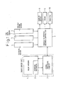
- FIG. 1 is a diagram showing an overview of the configuration of a vehicle-to-vehicle distance control system using a scanning radar in which the method of the present invention is employed.
- a radar sensor unit is, for example, an FM-CW radar, and includes a radar antenna 1, a scanning mechanism 2, and a signal processing circuit 3.
- a vehicle-to-vehicle distance control ECU 7 receives signals from a steering sensor 4, a yaw rate sensor 5, and a vehicle speed sensor 6 as well as from the signal processing circuit 3 in the radar sensor unit, and controls a warning device 8, a brake 9, a throttle 10, etc.
- the vehicle-to-vehicle distance control ECU 7 also sends a signal to the signal processing circuit 3 in the radar sensor unit.
- the radar to be used here need not necessarily be limited to the FM-CW radar.
- FIG 2 is a diagram showing the configuration of the signal processing circuit 3 of Figure 1.
- the signal processing circuit 3 comprises a scanning angle control section 11, a radar signal processing section 12, and a control target recognizing section 13.
- the radar signal processing section 12 applies an FFT to the reflected signal received by the radar antenna 1, detects the power spectrum, computes the distance and relative velocity of the target, and supplies the resulting data to the control target recognizing section 13. Based on the distance and relative velocity of the target supplied from the radar signal processing section 12, and on vehicle information detected by the steering sensor 4, yaw rate sensor 5, vehicle speed sensor 6, etc.
- the control target recognizing section 13 identifies the control target and supplies the result to the vehicle-to-vehicle distance control ECU, while at the same time, providing a commanded scanning angle to the scanning angle control section 11.
- the scanning angle control section 11 is one that, in the case of a fixed type radar, controls the beam projection angle, etc. when the vehicle is traveling around a curve and, in the case of a scanning radar, controls the beam scanning angle.
- the scanning control mechanism 2 performs scanning by sequentially projecting the beam at the required angle.
- FM-CW radar transmits a continuous wave frequency-modulated, for example, in a triangular pattern, to determine the distance to a target, such as a vehicle, traveling ahead. More specifically, the transmitted wave from the radar is reflected by the vehicle ahead, and the reflected signal is received and mixed with a portion of the transmitted signal to produce a beat signal (radar signal). This beat signal is fast Fourier transformed to analyze the frequency. The frequency-analyzed beat signal exhibits a peak at which the power becomes large in correspondence with the target; the frequency corresponding to this peak is called the peak frequency. The peak frequency carries information concerning the distance, and the peak frequency differs between the rising portion and falling portion of the triangular FM-CW wave due to the Doppler effect associated with the relative velocity with respect to the vehicle ahead.
- the distance and relative velocity with respect to the vehicle ahead are determined from the peak frequencies in the rising and falling portions.
- a pair of peak frequencies in the rising and falling portions is generated for each vehicle. Forming pairs of peak frequencies in the rising and falling portions is called pairing.
- FIGS 3A to 3C are diagrams for explaining the principle of the FM-CW radar when the relative velocity with respect to the target is 0.
- the transmitted wave is a triangular wave whose frequency changes as shown by a solid line in Figure 3A.
- f 0 is the transmit center frequency of the transmitted wave
- ⁇ f is the FM modulation width
- Tm is the repetition period.
- the transmitted wave is reflected from the target and received by the antenna; the received wave is shown by a dashed line in Figure 3A.
- the received wave is shifted in frequency from the transmitted signal (i.e., produces a beat) according to the distance between the radar and the target.
- the beat signal frequency component fb shown in Figure 3B can be expressed by the following equation.
- FIGs 4A to 4C are diagrams for explaining the principle of the FM-CW radar when the relative velocity with respect to the target is v.
- the frequency of the transmitted wave changes as shown by a solid line in Figure 4A.
- the transmitted wave is reflected from the target and received by the antenna; the received wave is shown by a dashed line in Figure 4A.
- the received wave is shifted in frequency from the transmitted signal (i.e., produces a beat) according to the distance between the radar and the target.
- the beat frequency component fb shown in Figure 4B can be expressed by the following equation.
- fr the frequency due to the distance
- fd is the frequency due to the velocity.
- FIG. 5 is a diagram showing an example of the configuration of the FM-CW radar.
- a modulating signal generator 21 applies a modulating signal to a voltage-controlled oscillator 22 for frequency modulation, and the frequency-modulated wave is transmitted out via the transmitting antenna AT, while a portion of the transmitted signal is separated and directed into a frequency converter 23 which functions like a mixer.
- the signal reflected from a target, such as a vehicle traveling ahead, is received via the receiving antenna AR, and the received signal is mixed in the frequency converter 23 with the output signal of the voltage-controlled oscillator 22 to produce a beat signal.
- the beat signal is passed through a baseband filter 24, and is converted by an A/D converter 25 into a digital signal; the digital signal is then supplied to a CPU 26 where signal processing such as fast Fourier transform is applied to the digital signal to obtain the distance and the relative velocity of the target.
- a vehicle B traveling ahead of the radar-equipped vehicle A is a large vehicle such as a truck
- a plurality of beams are reflected from the vehicle B.
- the reception levels of the peaks occurring due to the beams projected at the angles ⁇ a to ⁇ g are distributed as plotted in Figure 7, because reception levels are high and the reflecting area is large in the case of a large reflecting target such as a truck.
- the peak frequencies are substantially the same as the distances to various parts of the target are approximately the same.
- the reception level from a large vehicle may exhibit two peaks as shown in Figure 7.
- the angle corresponding to the peak of the reception level is taken as the angle at which the target is located.
- the peaks may be erroneously recognized as representing two separate targets.
- any peak appearing within a prescribed angle range ⁇ x from the largest peak is also regarded as representing the same target, and the center angle between the angles of the peaks is taken as the angle representing the target.
- the largest peak Pc and another peak Pf which is larger than the threshold value Pth and is located within the prescribed angle range ⁇ x from the largest peak Pc, are regarded as peaks representing the same target, and the center angle ⁇ 0 of the peaks Pc and Pf is taken as the angle representing the target.
- the peaks may not represent the same target, and even if they do represent the same target, the smaller peak may be one representing a portion other than the major portion of the target; in that case, the center angle is less likely to represent the center portion of the target.
- only a peak whose reception level is not smaller than that of the largest peak by more than a predetermined value is regarded as a peak of the signal reflected from the same target, and the center angle of these peaks is taken as the angle representing the target.
- the center angle between the angle of the leftmost peak Pb and the angle of the rightmost peak Pd or Pf is taken as the angle representing the target.
- the center angle between the angles of the leftmost and rightmost peaks in the peak group consisting of the largest peak and those some of the peaks is taken as the angle representing the target.
- the present invention utilizes the positional relationship between the reflection from the rear of the large vehicle and the reflection from the front side mirror or nearby portion of the vehicle, and determines that both reflections are from the large vehicle traveling in a neighboring lane.
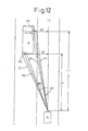
- Figure 12 shows the radar-equipped vehicle A traveling on a straight road and the large vehicle B traveling ahead in the neighboring lane.
- beams are projected from the radar-equipped vehicle A to the large vehicle B, and that one of the beams is reflected from a point P1 near a mirror of the target vehicle B and another beam from a point P2 on the rear of the vehicle B.
- the peak frequencies based on the beams reflected from P1 and P2, respectively are different but are approximately the same as the distance between these points is close.
- peaks having approximately the same frequency are selected from the rising portion and falling portion, respectively, and the plurality of peaks are paired up between the rising portion and the falling portion.
- the distances to the respective points P1 and P2, their relative velocities, and their displacement lengths, are detected.
- the thus detected distances to the points P1 and P2 in the traveling direction of the radar-equipped vehicle A are denoted by r1 and r2, respectively, and the relative velocities of the points P1 and P2 with respect to the radar-equipped vehicle A are denoted by v1 and v2, respectively, while the lengths of the perpendiculars (the lengths of the displacements) drawn from the points P1 and P2 to a straight line Ls extending along the traveling direction of the radar-equipped vehicle A are designated by 11 and 12, respectively.
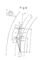
- Figure 13 shows the radar-equipped vehicle A traveling around a curve and the large vehicle B traveling ahead in a neighboring lane.
- beams are projected from the radar-equipped vehicle A to the large vehicle B, and that one of the beams is reflected from point P1 near a mirror of the target vehicle B and another beam from point P2 on the rear of the vehicle B.
- the distances of the points P1 and P2 along the extended line Ls in the traveling direction of the radar-equipped vehicle A are denoted by r1 and r2, respectively, and the relative velocities of the points P1 and P2 with respect to the radar-equipped vehicle A are denoted by v1 and v2, respectively, while the lengths of the perpendiculars drawn from the points P1 and P2 to the straight line Ls extending along the traveling direction of the radar-equipped vehicle A are denoted by 11 and 12, respectively, and the lengths of the lines extended from the points where 11 and 12 intersect with the straight line Ls to the points where they intersect with a curved line Lc along which the radar-equipped vehicle is expected to travel are denoted by x1 and x2, respectively.
- x2 can be obtained in a similar manner.
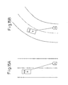
- Figures 15A and 15B are diagrams showing a large vehicle such as a truck traveling in a neighboring lane ahead of the radar-equipped vehicle.
- Figure 15A shows the vehicles traveling on a straight road
- Figure 15B shows the vehicles traveling around a curve.
- a large vehicle such as a truck tends to move nearer to the inside line of the lane as shown than when it is traveling on a straight road as shown in Figure 15A.
- a correction is made so that the target is located in the center of the curved lane. This correction is accomplished by correcting the angle ⁇ indicating the position of the target; more specifically, the closer the radar-equipped vehicle A is to the vehicle B traveling ahead, the greater the correction angle ⁇ is made.
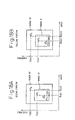
- Figures 16A and 16B are diagrams showing how the correction is made.
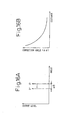
- Figure 16A shows that the angle of the peak P of the reflected signal from the target is corrected by ⁇ toward the center of the lane to shift it to the position P'.
- ⁇ is varied as shown in Figure 16B as a function of the distance to the vehicle ahead. That is, the correction angle ⁇ is reduced as the distance increases.
- FM-CW radar transmits a triangular-shaped frequency-modulated continuous wave to determine the distance to a target such as a vehicle traveling ahead. More specifically, the transmitted wave from the radar is reflected by the vehicle ahead, and a beat signal (radar signal) occurring between the received reflected wave signal and the transmitted signal is obtained. This beat signal is fast Fourier transformed to analyze the frequency. The frequency-analyzed beat signal exhibits a peak at which the power becomes large in correspondence with the target; the frequency corresponding to this peak is called the peak frequency. The peak frequency carries information concerning the distance, and the peak frequency differs between the rising portion and falling portion of the triangular FM-CW wave due to the Doppler effect associated with the relative velocity with respect to the vehicle ahead.
- the distance and relative velocity with respect to the vehicle ahead are determined from the peak frequencies in the rising and falling portions.
- a pair of peak frequencies in the rising and falling portions is generated for each vehicle. Forming pairs of peak frequencies in the rising and falling portions is called pairing.
- Figures 17A and 17B are graphs in which the angle of the peak of the signal reflected from the target is plotted as abscissa and the peak frequency as ordinate.
- a range R1 and a range R2 wider than the range R1 are defined for each of Pu-max and Pd-max; first, the range R1 in the rising portion is searched to find if there is any peak therein and, if there is a peak, the frequency f up1 and angle ⁇ up1 of that peak are obtained (S1), and the peak is plotted as P c as shown in Figure 18A.
- ⁇ F is the frequency difference between Pu-max and Pd-max
- x is a constant.
- This expression means that the difference between f up1 and f dw1 that is greater than the frequency difference between Pu-max and Pd-max is permitted. That is, in the case of the peaks contained in the range R1, correct pairing can be accomplished even if the difference between f up1 and f dw1 is somewhat larger than ⁇ F.
- the value of x is appropriately set within a range in which correct pairing can be done.
- the range R2 in the rising portion is searched to find if there is any peak therein other than the peak found in the range R1 and, if there is a peak, the frequency f up2 and angle ⁇ up2 of that peak are obtained (S5), and the peak is plotted as P D as shown in Figure 18A.
- y is a constant, as is x.
- y is a constant, as is x.
- the target is a large vehicle, but it should be understood that the target that gives rise to a plurality of peaks in the reception level is not limited to a large vehicle. It should also be noted that the target that reflects beams from differently located parts is not limited to a large vehicle. Accordingly, in the present invention, the target is not limited to a large vehicle.
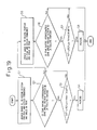
- Figures 20A and 20B show an example of a flowchart illustrating the method of the present invention described in the first to third embodiments.
- control or decision-making operations in the respective steps are performed in the signal processing circuit 3 shown in Figure 1.
- peaks having substantially the same frequency are grouped together. For any target located at the same distance from the radar-equipped vehicle, peak frequencies are substantially the same. For example, in the case of a large vehicle, beams are reflected from a plurality of differently located parts, and a plurality of peaks occur. In view of this, peaks having substantially the same frequency are grouped together.
- S2 it is determined whether or not the reception level of each of the thus grouped peaks is equal to or higher than a predetermined value (threshold value). This decision step is included because the detected peak level is high if the target is a large vehicle. If the answer to S2 is Yes, then it is determined whether the detection angles of the peaks having substantially the same frequency lie within a predetermined range (S3). This determination is made by checking whether the detection angle range between the peaks at both ends of the peak group is within the predetermined range. If the answer to S3 is Yes, the process proceeds to S4, and it is determined if the difference in reception level between the peaks is within a predetermined value (threshold value). This step is performed to combine peaks between which the difference in reception level is relatively small. If the answer to S4 is Yes, re-grouping is performed. That is, the peaks are grouped together as representing the same target (S5).
- the difference in reception level between the re-grouped peaks is small or not (S6).
- the value with which the difference in reception level is compared here is set smaller than the value used in S4. If the difference between the peak reception levels is small, that is, if the reception levels are substantially the same (Yes), the probability is that a plurality of beams are reflected at the same intensity from the rear of a large vehicle such as a truck or a bus; therefore, of the re-grouped peaks, the center angle between the angle of the leftmost peak and the angle of the rightmost peak is taken as the angle representing the target (S7).
- the angle of the large peak i.e., the maximum peak, is taken as the angle representing the target (S8).
- the peak frequencies are paired up between the rising and falling portions, and in S10, the distance, relative velocity, detection angle, and the length of the lateral displacement from the lane in which the radar-equipped vehicle is traveling are obtained for each of the portions from which the plurality of beams have been reflected.
- the pairing is performed, for example, as explained in the description of the third embodiment.
- the length of the displacement is obtained as explained in the description of the second embodiment.
- past data is taken over in order to maintain the target data continuity.
- S12 it is determined whether the differences in distance, in relative velocity, and in the length of the lateral displacement from the lane in which the radar-equipped vehicle is traveling, existing between the respective reflecting portions, are within the respectively predetermined values (threshold values: ⁇ r, ⁇ v, and ⁇ l). If the differences in distance, in relative velocity, in angle, and in the length of the lateral displacement from the lane, existing between the respective portions of the target detected based on the respective peaks, are within the respectively predetermined values (Yes), the peaks can be considered as being peaks representing the same target, and a large vehicle decision counter is counted up. More specifically, the counter is incremented by 1 (S13). This counting is done each time the flow is processed.
- S14 it is determined whether the value of the large vehicle decision counter has reached a predetermined value. This step is necessary because the target considered to be a large vehicle in the first cycle of flow cannot always be determined as being a large vehicle, as there is a possibility that a plurality of peaks arising from two vehicles traveling ahead side by side, for example, happen to satisfy the conditions set in S12, leading to an erroneous decision that the peaks are from a large vehicle. If the counter value has reached the predetermined value in S14 (Yes), then the target is determined as being a large vehicle (S15). On the other hand, if the counter value has not yet reached the predetermined value (No), the current cycle of flow is terminated, and the process proceeds to the next cycle of flow.
- the distances and relative velocities obtained from the peaks based on the beams reflected from the farther parts of the vehicle, such as front parts of the vehicle including, for example, a front side mirror or a nearby part, are excluded from output data (S16).
- the angle of the peak arising from the reflecting point located at the shortest distance from the radar-equipped vehicle is taken as the angle representing the target.
- the target position obtained from the peak based on the beam reflected from the rear of the vehicle is determined as being the position of the control target.
- the angle at which the large vehicle is detected is corrected and shifted outward as shown in Figure 16A (S17), after which the flow is terminated. Whether the target is located in the neighboring lane or not can be determined in accordance with the method explained in the description of the second embodiment.
Landscapes
- Engineering & Computer Science (AREA)
- Radar, Positioning & Navigation (AREA)
- Remote Sensing (AREA)
- Physics & Mathematics (AREA)
- Computer Networks & Wireless Communication (AREA)
- General Physics & Mathematics (AREA)
- Signal Processing (AREA)
- Electromagnetism (AREA)
- Radar Systems Or Details Thereof (AREA)
Abstract
Description
it is determined that the target is traveling in the neighboring lane.
Claims (14)
- A signal processing method for a scanning radar wherein, of peaks generated based on a radar signal reflected from a target, peaks whose frequencies are substantially the same and whose reception levels are not smaller than a predetermined value are selected and, when a plurality of such peaks are selected, a center angle between the angles of the leftmost and rightmost peaks is obtained, and said obtained center angle is taken as an angle representing said target.
- A signal processing method for a scanning radar as claimed in claim 1, wherein when the number of said selected peaks is two, the angle of a peak located within a predetermined angle range from the larger peak is obtained, and a center angle between the angle of said peak and the angle of said larger peak is obtained and is taken as the angle representing said target.
- A signal processing method for a scanning radar as claimed in claim 2, wherein said center angle is taken as the angle representing said target, only when the difference between the reception level of said larger peak and the reception level of said peak located within said predetermined angle range from said larger peak is not greater than a predetermined value.
- A signal processing method for a scanning radar as claimed in claim 2 wherein, when the difference between the reception level of said larger peak and the reception level of said peak located within said predetermined angle range from said larger peak is greater than a predetermined value, the angle of said larger peak is taken as the angle representing said target.
- A signal processing method for a scanning radar as claimed in claim 1 wherein, when the number of said selected peaks is three or larger, said center angle is taken as the angle representing said target, only when the difference between the reception level of the largest peak of said three or more peaks and the reception level of each of the remaining peaks is not greater than a predetermined value.
- A signal processing method for a scanning radar as claimed in claim 1 wherein, when the number of said selected peaks is three or larger, and when the difference between the reception level of the largest peak of said three or more peaks and the reception level of each of the remaining peaks is greater than a predetermined value, the angle of said largest peak is taken as the angle representing said target.
- A signal processing method for a scanning radar as claimed in claim 1 wherein, when the number of said selected peaks is three or larger, and when the difference between the reception level of the largest peak of said three or more peaks and the reception level of each of a plurality of peaks taken from among the remaining peaks is not greater than a predetermined value, a center angle between the angles of the leftmost and rightmost peaks in a peak group consisting of said largest peak and said plurality of peaks is obtained, and said obtained center angle is taken as the angle representing said target.
- A signal processing method for a scanning radar wherein, of peaks generated based on a radar signal reflected from a target, a plurality of peaks whose frequencies are substantially the same are selected, and pairing is performed on said plurality of peaks to detect a distance, relative velocity, and displacement length for each of reflecting points on said target, and wherein when the differences in said detected distance, relative velocity, and displacement length, existing between said reflecting points, are all within respectively predetermined values, said plurality of peaks are determined as being peaks representing the same target.
- A signal processing method for a scanning radar as claimed in claim 8 wherein, of said plurality of peaks, the angle of the peak arising from the reflecting point whose detected distance is the shortest is taken as an angle representing said target.
- A signal processing method for a scanning radar as claimed in claim 8, wherein said same target is determined as being a large vehicle.
- A signal processing method for a scanning radar as claimed in claim 8 wherein, when said displacement length is greater than a predetermined value, it is determined that said target is traveling in a neighboring lane.
- A signal processing method for a scanning radar as claimed in claim 8 wherein, when it is determined that said target is traveling in a neighboring lane around a curve, a correction is made so that said target is located in the center of said lane.
- A signal processing method for a scanning radar wherein, of peaks generated based on a radar signal reflected from a target, peak signals whose reception levels are the largest in rising and falling portions, respectively, of said radar signal are extracted for pairing therebetween, after which peak signals located at equivalent positions in terms of angle and frequency differences relative to the respective peak signals whose reception levels are the largest are extracted from said rising and falling portions, respectively, for pairing therebetween.
- A signal processing method for a scanning radar wherein, of peaks generated based on a radar signal reflected from a target, peak signals whose reception levels are the largest in rising and falling portions, respectively, of said radar signal are extracted for pairing therebetween, a range R1 defined by predetermined frequency and angle ranges containing the frequency and angle of each of said largest peak signals and a range R2 wider than said range 1 are determined, and said ranges R1 and R2 are searched for peaks having substantially the same angle in said rising and falling portions, respectively and wherein, when said peaks are located in said range R1, said peaks are paired up if the difference in frequency between said peaks is within a first predetermined range, but when said peaks are located in said range R2, said peaks are paired up if the difference in frequency between said peaks is within a second predetermined range which is smaller than said first predetermined range.
Applications Claiming Priority (3)
| Application Number | Priority Date | Filing Date | Title |
|---|---|---|---|
| JP2001074610 | 2001-03-15 | ||
| JP2001074610 | 2001-03-15 | ||
| PCT/JP2002/002519 WO2002075355A1 (en) | 2001-03-15 | 2002-03-15 | Signal processing method for scanning radar |
Publications (3)
| Publication Number | Publication Date |
|---|---|
| EP1369705A1 true EP1369705A1 (en) | 2003-12-10 |
| EP1369705A4 EP1369705A4 (en) | 2005-10-26 |
| EP1369705B1 EP1369705B1 (en) | 2009-12-30 |
Family
ID=18931844
Family Applications (1)
| Application Number | Title | Priority Date | Filing Date |
|---|---|---|---|
| EP02705274A Expired - Lifetime EP1369705B1 (en) | 2001-03-15 | 2002-03-15 | Signal processing method for scanning radar |
Country Status (6)
| Country | Link |
|---|---|
| US (1) | US6900754B2 (en) |
| EP (1) | EP1369705B1 (en) |
| KR (1) | KR100662064B1 (en) |
| CN (1) | CN100359337C (en) |
| DE (1) | DE60234911D1 (en) |
| WO (1) | WO2002075355A1 (en) |
Cited By (1)
| Publication number | Priority date | Publication date | Assignee | Title |
|---|---|---|---|---|
| WO2006034886A1 (en) * | 2004-09-28 | 2006-04-06 | Robert Bosch Gmbh | Radar sensor and method for regulating the distance and speed |
Families Citing this family (45)
| Publication number | Priority date | Publication date | Assignee | Title |
|---|---|---|---|---|
| EP1310804B1 (en) * | 2001-11-08 | 2010-12-22 | Fujitsu Ten Limited | Scan type radar device |
| JP3997837B2 (en) * | 2002-05-27 | 2007-10-24 | 株式会社デンソー | In-vehicle radar device, program |
| US6906661B2 (en) * | 2002-10-17 | 2005-06-14 | Honda Motor Co., Ltd. | Object-detecting system for vehicle |
| US7136753B2 (en) * | 2002-12-05 | 2006-11-14 | Denso Corporation | Object recognition apparatus for vehicle, inter-vehicle control apparatus, and distance measurement apparatus |
| EP1528407A1 (en) * | 2003-10-31 | 2005-05-04 | Mitsubishi Electric Information Technology Centre Europe B.V. | Decomposition of a wideband random signal |
| JP3931891B2 (en) * | 2004-07-05 | 2007-06-20 | 日産自動車株式会社 | In-vehicle image processing device |
| JP2006151125A (en) * | 2004-11-26 | 2006-06-15 | Omron Corp | In-vehicle image processing device |
| CN100414317C (en) * | 2004-12-17 | 2008-08-27 | 电子科技大学 | A Non-perfect Matching Processing Method for Pseudo-Random Composite Modulation Signal |
| US7706978B2 (en) * | 2005-09-02 | 2010-04-27 | Delphi Technologies, Inc. | Method for estimating unknown parameters for a vehicle object detection system |
| DE102005053510A1 (en) * | 2005-11-09 | 2007-05-10 | Siemens Ag | Motor vehicle for automotive vehicle communication and associated method for operating an antenna structure of a motor vehicle |
| JP4265803B2 (en) * | 2005-11-22 | 2009-05-20 | 三菱電機株式会社 | Radar system |
| JP2007155469A (en) * | 2005-12-05 | 2007-06-21 | Alpine Electronics Inc | Inter-vehicle distance detection system and inter-vehicle distance detection method |
| JP4684876B2 (en) * | 2005-12-14 | 2011-05-18 | 富士通テン株式会社 | Radar device and method for detecting object of radar device |
| US7715701B2 (en) * | 2006-06-21 | 2010-05-11 | Lange Frederick M | Camera systems, methods and units therefor |
| JP4697072B2 (en) * | 2006-07-04 | 2011-06-08 | 株式会社デンソー | Radar equipment |
| JP4518080B2 (en) * | 2007-01-09 | 2010-08-04 | トヨタ自動車株式会社 | Perimeter monitoring device |
| JP5380788B2 (en) * | 2007-05-30 | 2014-01-08 | トヨタ自動車株式会社 | Object detection device and vehicle control device |
| JP4353298B2 (en) * | 2007-12-13 | 2009-10-28 | オムロン株式会社 | Non-contact IC medium direction detection device and method, and program thereof |
| FR2940465B1 (en) * | 2008-12-18 | 2010-12-31 | Valeo Vision Sas | METHOD FOR DETECTING A TARGET OBJECT FOR A MOTOR VEHICLE |
| DE102010037163B4 (en) * | 2009-08-27 | 2017-12-21 | Fujitsu Ten Ltd. | Signal processing apparatus, radar apparatus, vehicle control system, signal processing method and computer readable medium |
| KR101034445B1 (en) * | 2009-12-11 | 2011-05-12 | 박정혁 | Artificial landscaping systems |
| TW201133412A (en) * | 2010-03-19 | 2011-10-01 | Cct Co Ltd | Method of using radar vehicle detector to determine vehicle type, speed, and radar detection zone width |
| JP5666987B2 (en) * | 2011-05-25 | 2015-02-12 | 株式会社デンソー | Moving object detection device |
| JP5989353B2 (en) | 2012-02-13 | 2016-09-07 | 株式会社デンソー | Radar equipment |
| JP6009775B2 (en) | 2012-02-13 | 2016-10-19 | 株式会社デンソー | Radar equipment |
| JP5996878B2 (en) | 2012-02-13 | 2016-09-21 | 株式会社デンソー | Radar equipment |
| JP6092596B2 (en) * | 2012-11-28 | 2017-03-08 | 富士通テン株式会社 | Radar apparatus and signal processing method |
| JP2014115137A (en) * | 2012-12-07 | 2014-06-26 | Fujitsu Ten Ltd | Radar apparatus and signal processing method |
| JP6020321B2 (en) * | 2013-04-11 | 2016-11-02 | 株式会社デンソー | Target detection apparatus and vehicle control system |
| JP2015081890A (en) * | 2013-10-24 | 2015-04-27 | 古野電気株式会社 | Signal processor and radar device |
| KR102202354B1 (en) * | 2013-11-06 | 2021-01-13 | 현대모비스 주식회사 | Fmcw radar system for detecting target using representative value and method thereof |
| JP6313981B2 (en) * | 2014-01-22 | 2018-04-18 | 株式会社デンソーテン | Radar apparatus, vehicle control system, and signal processing method |
| JP2015141109A (en) * | 2014-01-29 | 2015-08-03 | 富士通テン株式会社 | Radar device and signal processing method |
| JP6338871B2 (en) * | 2014-01-31 | 2018-06-06 | 株式会社デンソーテン | Radar apparatus, vehicle control system, and signal processing method |
| KR101582404B1 (en) * | 2014-03-21 | 2016-01-04 | 한양대학교 산학협력단 | Method and apparatus for counting number of object using uwb radar |
| EP3007150A1 (en) * | 2014-10-07 | 2016-04-13 | Autoliv Development AB | Lane change detection |
| JP6534808B2 (en) * | 2014-11-28 | 2019-06-26 | 株式会社デンソーテン | Radar apparatus and signal processing method |
| KR102435550B1 (en) * | 2015-06-09 | 2022-08-24 | 주식회사 에이치엘클레무브 | Apparatur for processing signal of radar and method for processing signal thereof |
| FR3050279B1 (en) * | 2016-04-19 | 2018-05-11 | Thales | AUTOMATIC CALCULATION OF A DIMENSION OF A MOBILE PLATFORM |
| CN110531341B (en) * | 2018-05-26 | 2023-04-11 | 苏州镭智传感科技有限公司 | FMCW laser radar using broadband frequency modulation laser and scanning method thereof |
| US11360214B2 (en) * | 2020-10-08 | 2022-06-14 | Aeva, Inc. | Techniques for ghosting mitigation in coherent lidar systems |
| CN114488124B (en) * | 2020-10-23 | 2025-06-17 | 华为技术有限公司 | A detection and communication system, a control device and a detection system |
| CN113734046B (en) * | 2021-08-17 | 2023-09-19 | 江苏星图智能科技有限公司 | Radar-based in-vehicle position zoned person detection method, device and equipment |
| US12194988B2 (en) * | 2022-04-01 | 2025-01-14 | GM Global Technology Operations LLC | Systems and methods for combining detected objects |
| KR20260040230A (en) * | 2023-07-21 | 2026-03-24 | 엘지전자 주식회사 | Method and apparatus for performing communication in a wireless communication system |
Family Cites Families (17)
| Publication number | Priority date | Publication date | Assignee | Title |
|---|---|---|---|---|
| JP2778864B2 (en) * | 1991-11-22 | 1998-07-23 | 富士通テン株式会社 | Millimeter wave radar distance / velocity measurement system |
| JP3401913B2 (en) * | 1994-05-26 | 2003-04-28 | 株式会社デンソー | Obstacle recognition device for vehicles |
| JP3627389B2 (en) * | 1995-09-28 | 2005-03-09 | 株式会社デンソー | Radar equipment |
| DE69611278T2 (en) * | 1995-11-10 | 2001-05-23 | Toyota Jidosha K.K., Toyota | Radar device for detecting the direction of the center of a target |
| JP3491418B2 (en) * | 1995-12-01 | 2004-01-26 | 株式会社デンソー | FMCW radar equipment |
| JP3460453B2 (en) * | 1995-12-11 | 2003-10-27 | 株式会社デンソー | FMCW radar equipment |
| JPH09222477A (en) * | 1996-02-19 | 1997-08-26 | Toyota Motor Corp | Automotive radar equipment |
| US5872536A (en) * | 1997-02-19 | 1999-02-16 | Hittite Microwave Corporation | Multi-sensor anticipatory object detection system |
| JP4082473B2 (en) * | 1997-12-19 | 2008-04-30 | 富士通テン株式会社 | Radar apparatus signal processing method and apparatus |
| JP3942722B2 (en) * | 1998-02-16 | 2007-07-11 | 本田技研工業株式会社 | In-vehicle radar system |
| JP3480486B2 (en) * | 1998-08-18 | 2003-12-22 | トヨタ自動車株式会社 | FM-CW radar device |
| JP2000075028A (en) * | 1998-08-27 | 2000-03-14 | Toyota Motor Corp | In-vehicle DBF radar device |
| JP3512066B2 (en) | 1998-12-10 | 2004-03-29 | トヨタ自動車株式会社 | Automotive radar equipment |
| JP4356820B2 (en) * | 1998-12-28 | 2009-11-04 | 本田技研工業株式会社 | Radar equipment |
| JP3995816B2 (en) | 1998-12-28 | 2007-10-24 | 本田技研工業株式会社 | Radar equipment |
| JP2000206241A (en) | 1999-01-13 | 2000-07-28 | Honda Motor Co Ltd | Radar device |
| JP2000298164A (en) | 1999-04-15 | 2000-10-24 | Honda Motor Co Ltd | Multi-channel radar device |
-
2002
- 2002-03-15 CN CNB028006933A patent/CN100359337C/en not_active Expired - Fee Related
- 2002-03-15 KR KR1020027014611A patent/KR100662064B1/en not_active Expired - Fee Related
- 2002-03-15 EP EP02705274A patent/EP1369705B1/en not_active Expired - Lifetime
- 2002-03-15 DE DE60234911T patent/DE60234911D1/en not_active Expired - Lifetime
- 2002-03-15 US US10/297,343 patent/US6900754B2/en not_active Expired - Fee Related
- 2002-03-15 WO PCT/JP2002/002519 patent/WO2002075355A1/en not_active Ceased
Cited By (2)
| Publication number | Priority date | Publication date | Assignee | Title |
|---|---|---|---|---|
| WO2006034886A1 (en) * | 2004-09-28 | 2006-04-06 | Robert Bosch Gmbh | Radar sensor and method for regulating the distance and speed |
| US7554485B2 (en) | 2004-09-28 | 2009-06-30 | Robert Bosch Gmbh | Radar sensor and method for distance and cruise control |
Also Published As
| Publication number | Publication date |
|---|---|
| CN100359337C (en) | 2008-01-02 |
| EP1369705B1 (en) | 2009-12-30 |
| US6900754B2 (en) | 2005-05-31 |
| US20030142007A1 (en) | 2003-07-31 |
| KR20030013394A (en) | 2003-02-14 |
| DE60234911D1 (en) | 2010-02-11 |
| WO2002075355A1 (en) | 2002-09-26 |
| EP1369705A4 (en) | 2005-10-26 |
| KR100662064B1 (en) | 2006-12-27 |
| CN1459029A (en) | 2003-11-26 |
Similar Documents
| Publication | Publication Date | Title |
|---|---|---|
| EP1369705B1 (en) | Signal processing method for scanning radar | |
| EP1357394B1 (en) | Still object detecting method of scanning radar | |
| EP1371997B1 (en) | Method for detecting stationary object on road by radar | |
| US6693583B2 (en) | Object recognition apparatus and method thereof | |
| JP4007498B2 (en) | Automotive radar equipment | |
| JP3797277B2 (en) | Radar | |
| EP1318415B1 (en) | Mispairing determination method for FM-CW radar | |
| JP4093109B2 (en) | Radar equipment for vehicles | |
| US6661370B2 (en) | Radar data processing apparatus and data processing method | |
| US20100271257A1 (en) | Radar apparatus | |
| US6798373B2 (en) | FM-CW radar system | |
| US20110084872A1 (en) | Signal processing apparatus and radar apparatus | |
| JP3744860B2 (en) | Scanning radar signal processing method | |
| JP4079739B2 (en) | Automotive radar equipment | |
| JP4064693B2 (en) | Scanning FM-CW radar signal processing method | |
| JP3723804B2 (en) | Automotive radar equipment | |
| JP4390916B2 (en) | Scanning radar equipment | |
| JP2007232747A (en) | On-board radar device | |
| JP3446428B2 (en) | Obstacle detection device |
Legal Events
| Date | Code | Title | Description |
|---|---|---|---|
| PUAI | Public reference made under article 153(3) epc to a published international application that has entered the european phase |
Free format text: ORIGINAL CODE: 0009012 |
|
| 17P | Request for examination filed |
Effective date: 20021209 |
|
| AK | Designated contracting states |
Kind code of ref document: A1 Designated state(s): AT BE CH CY DE DK ES FI FR GB GR IE IT LI LU MC NL PT SE TR |
|
| AX | Request for extension of the european patent |
Extension state: AL LT LV MK RO SI |
|
| A4 | Supplementary search report drawn up and despatched |
Effective date: 20050907 |
|
| GRAP | Despatch of communication of intention to grant a patent |
Free format text: ORIGINAL CODE: EPIDOSNIGR1 |
|
| GRAS | Grant fee paid |
Free format text: ORIGINAL CODE: EPIDOSNIGR3 |
|
| GRAA | (expected) grant |
Free format text: ORIGINAL CODE: 0009210 |
|
| AK | Designated contracting states |
Kind code of ref document: B1 Designated state(s): DE FR GB |
|
| REG | Reference to a national code |
Ref country code: GB Ref legal event code: FG4D |
|
| REF | Corresponds to: |
Ref document number: 60234911 Country of ref document: DE Date of ref document: 20100211 Kind code of ref document: P |
|
| PLBE | No opposition filed within time limit |
Free format text: ORIGINAL CODE: 0009261 |
|
| STAA | Information on the status of an ep patent application or granted ep patent |
Free format text: STATUS: NO OPPOSITION FILED WITHIN TIME LIMIT |
|
| 26N | No opposition filed |
Effective date: 20101001 |
|
| REG | Reference to a national code |
Ref country code: FR Ref legal event code: PLFP Year of fee payment: 14 |
|
| PGFP | Annual fee paid to national office [announced via postgrant information from national office to epo] |
Ref country code: DE Payment date: 20150310 Year of fee payment: 14 |
|
| PGFP | Annual fee paid to national office [announced via postgrant information from national office to epo] |
Ref country code: GB Payment date: 20150311 Year of fee payment: 14 Ref country code: FR Payment date: 20150309 Year of fee payment: 14 |
|
| REG | Reference to a national code |
Ref country code: DE Ref legal event code: R119 Ref document number: 60234911 Country of ref document: DE |
|
| GBPC | Gb: european patent ceased through non-payment of renewal fee |
Effective date: 20160315 |
|
| REG | Reference to a national code |
Ref country code: FR Ref legal event code: ST Effective date: 20161130 |
|
| PG25 | Lapsed in a contracting state [announced via postgrant information from national office to epo] |
Ref country code: GB Free format text: LAPSE BECAUSE OF NON-PAYMENT OF DUE FEES Effective date: 20160315 Ref country code: FR Free format text: LAPSE BECAUSE OF NON-PAYMENT OF DUE FEES Effective date: 20160331 Ref country code: DE Free format text: LAPSE BECAUSE OF NON-PAYMENT OF DUE FEES Effective date: 20161001 |