EP1369704A1 - Formations orientées le long du trajet de satellites SAR - Google Patents
Formations orientées le long du trajet de satellites SAR Download PDFInfo
- Publication number
- EP1369704A1 EP1369704A1 EP03291323A EP03291323A EP1369704A1 EP 1369704 A1 EP1369704 A1 EP 1369704A1 EP 03291323 A EP03291323 A EP 03291323A EP 03291323 A EP03291323 A EP 03291323A EP 1369704 A1 EP1369704 A1 EP 1369704A1
- Authority
- EP
- European Patent Office
- Prior art keywords
- sar
- pairs
- antenna
- same
- signal
- Prior art date
- Legal status (The legal status is an assumption and is not a legal conclusion. Google has not performed a legal analysis and makes no representation as to the accuracy of the status listed.)
- Granted
Links
Images


Classifications
-
- G—PHYSICS
- G01—MEASURING; TESTING
- G01S—RADIO DIRECTION-FINDING; RADIO NAVIGATION; DETERMINING DISTANCE OR VELOCITY BY USE OF RADIO WAVES; LOCATING OR PRESENCE-DETECTING BY USE OF THE REFLECTION OR RERADIATION OF RADIO WAVES; ANALOGOUS ARRANGEMENTS USING OTHER WAVES
- G01S13/00—Systems using the reflection or reradiation of radio waves, e.g. radar systems; Analogous systems using reflection or reradiation of waves whose nature or wavelength is irrelevant or unspecified
- G01S13/003—Bistatic radar systems; Multistatic radar systems
-
- G—PHYSICS
- G01—MEASURING; TESTING
- G01S—RADIO DIRECTION-FINDING; RADIO NAVIGATION; DETERMINING DISTANCE OR VELOCITY BY USE OF RADIO WAVES; LOCATING OR PRESENCE-DETECTING BY USE OF THE REFLECTION OR RERADIATION OF RADIO WAVES; ANALOGOUS ARRANGEMENTS USING OTHER WAVES
- G01S13/00—Systems using the reflection or reradiation of radio waves, e.g. radar systems; Analogous systems using reflection or reradiation of waves whose nature or wavelength is irrelevant or unspecified
- G01S13/88—Radar or analogous systems specially adapted for specific applications
- G01S13/89—Radar or analogous systems specially adapted for specific applications for mapping or imaging
- G01S13/90—Radar or analogous systems specially adapted for specific applications for mapping or imaging using synthetic aperture techniques, e.g. synthetic aperture radar [SAR] techniques
- G01S13/9021—SAR image post-processing techniques
- G01S13/9023—SAR image post-processing techniques combined with interferometric techniques
-
- G—PHYSICS
- G01—MEASURING; TESTING
- G01S—RADIO DIRECTION-FINDING; RADIO NAVIGATION; DETERMINING DISTANCE OR VELOCITY BY USE OF RADIO WAVES; LOCATING OR PRESENCE-DETECTING BY USE OF THE REFLECTION OR RERADIATION OF RADIO WAVES; ANALOGOUS ARRANGEMENTS USING OTHER WAVES
- G01S13/00—Systems using the reflection or reradiation of radio waves, e.g. radar systems; Analogous systems using reflection or reradiation of waves whose nature or wavelength is irrelevant or unspecified
- G01S13/88—Radar or analogous systems specially adapted for specific applications
- G01S13/89—Radar or analogous systems specially adapted for specific applications for mapping or imaging
- G01S13/90—Radar or analogous systems specially adapted for specific applications for mapping or imaging using synthetic aperture techniques, e.g. synthetic aperture radar [SAR] techniques
- G01S13/904—SAR modes
- G01S13/9058—Bistatic or multistatic SAR
Definitions
- the present invention relates to instrument sets for soil observations.
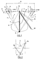
- Figure 1 shows the operating principle of an instrument or SAR 1 moving on a trajectory 3 in the direction indicated by the vector speed V.
- each mid-point line in the position of the SAR 1 is distant from the previous or the next by a distance 11 equal to V / PRF, where V is the speed of movement of the SAR 1 , and PRF is the "Pulse Repetition Frequency" according to the generally used English terminology, or pulse repetition frequency.
- Figure 1 shows that with signal processing known to humans of the trade and called SAR correction, the small SAR 1 replaces a large antenna 2 which would be wrapped around the object 6 to be observed, but which would of such a length that it is impossible to achieve.
- the principle of SAR is to be able to have a resolution identical to that of a huge antenna despite the small size of the antenna 1.
- the SAR 1 lobe is in the shape of the one referenced par 4
- the corrected addition of signals on all positions of SAR 1 above the object 6 to be observed makes it possible to obtain a narrower total lobe 5, which corresponds to that of the large antenna 2.
- the principle of SAR signal processing is based on a compensation for the delay in observing object 6 between the different SAR 1 positions on path 3.
- FIG. 2 shows that a transmitter 1a and a receiver 1b placed substantially in the same virtual tube around a star are equivalent, from the point of view of treatment signal, to a single transceiver 1 placed in the middle position of the positions of instruments 1a and 1b along the X and Y axes.
- the transmitter 1a throughout its journey, sends a succession of signals towards the object 6. After reflection on the ground, the samples are received receiver 1b.
- the received signal samples are then added together in mode complex. This addition takes place after each signal has received a time advance.
- the time advance corresponds to the supplement of time of each double journey (since there is a round trip between the program and signal reception) referenced by 9 in Figure 1, relative to the double path referenced by 8 in FIG. 1.
- Paths 7 represent the distance from SAR 1 to target 6.
- the specific double path 8 corresponds to the path between the particular midpoint 18, between the transmitter and the receiver on trajectory 3, and target 6.
- the time advance is made at the midpoint between the emission of the sample and its reception for SAR 1 placed at 18.
- the length of the synthetic antenna is referenced by 13 in FIG. 1.
- Figure 1 shows indeed, that there is what the skilled person calls ambiguities, of which two lobes 50 and 51 have been represented here, which extend on the sides of the detection lobe 5 of the synthetic antenna. Yes they are not eliminated in one way or another, these ambiguities cause a disturbance of the main observation signal.
- ambiguous directions are rotated, with respect to the vertical, by k ⁇ PRF / 2V where k is a number integer, V is the speed of movement of the SAR and where PRF is the frequency sampling.
- the directions of ambiguities determine the minimum size of SAR 1. Indeed, the size of the SAR is determined so that the detection lobe of the real antenna 4 does not include the first ambiguity 50, so as not to disturb the reception signal. Which leads to having a length real antenna at least greater than 2V / PRF (at least two lengths sampling).
- the antenna surface is a key element of performance space SAR and its complexity.
- the antenna area and the power are the main constraints of SAR sizing. These two constraints limit the ratio of mowed to resolution, which is the key criterion and which is referred to as the merit factor.
- the critical dimensioning of the SAR is that which maximizes the factor merit for a given antenna area. Going beyond creates an area much stronger antenna (+ 100%), for a gain in merit factor relatively low (50%). However, the merit factor loses a lot of its value (-75%) compared to the savings on the antenna surface (-30%) if we pass below the critical dimensioning.
- the merit factor has a value of 10,000 at critical size, for an incidence at target 6 with a value of 50 ° to 60 °.
- the object of the invention is to propose several SAR on the same path.
- the invention thus proposes the addition of several SARs, without having hard constraints on the position of the SAR between them.
- Another object of the invention is to reduce the constraints on the power and on the antenna area by diluting them on a plurality of antennas. It is technically easier to build more antennas small.
- Another object of the invention is to remove the limit on the factor of merit and multiply the achievable merit factor for an area given antenna.
- the invention proposes this distribution on separate satellites thanks to, among others, to a choice of waveform which circumvents the constraints of positioning.
- the invention proposes a signal processing method and for guiding several instruments comprising means forming synthetic aperture radars for the observation of a target, the instruments comprising at least one pair formed by a transmitter and a receiver, characterized in that the addition is repeated, corrected for path differences A / R to the target, in complex mode of samples from a plurality of pairs each differentiated by their transmitter and / or their receiver, all the additions being carried out on pairs whose midpoint is substantially located, in a local coordinate system linked to the target and at the time of the corrected addition, on the same section of the corresponding trajectory approximately the length of the synthetic antenna formed by the radars.
- the invention also relates to a set of instruments allowing the implementation of the process described.
- the invention also relates to the set of instruments allowing the method according to the invention to be implemented.
- This set is advantageously completed by the fact that the instruments are carried by satellites around a star.
- the different embodiments are all based on an N SAR flight on the same orbital arc as seen from the ground and a special case is when the N SAR are in visibility, only one being in emission.
- N SARs fly in the same orbital arc around the earth. This means that the SARs are generally in different orbital planes at because of the rotation of the earth on itself between the passages of different SAR. However, the time delay due to this phenomenon is less than what could cause a temporal decorrelation of the backscatter. In the following description, not all the SARs are visibility, despite the fact that more satellites in visibility allows multistatic configurations, where only one SAR transmits, and where everyone else receives.
- the swath is the surface swept on the surface of the ground by a detection satellite.
- the resolution azimuth is the footprint on the ground along the velocity vector of the beam formed by the synthetic antenna. (That is to say the end to end of the different positions of the real antenna between the instant when the real beam begins to see the target and when it stops seeing it.)
- the synthetic antenna is so the longer (and the azimuth resolution good) that the beam real is wide and the real antenna short
- a train of N SAR in visibility facilitates training metrology (DGPS) and the overall energy efficiency is increased by N because with a SAR in single emission, the same performances are obtained. Moreover, the orbital constraints are reduced by 2.
- each embodiment can eliminate the problem of large antenna sizes for a SAR mission in P-band or at very high altitude, especially since in this case, the constraints of width of SAR formation tube (function of ⁇ and altitude) are reduced.
- This description is preferably dedicated to instruments in orbit around a star.
- the invention is applicable also instruments in the aeronautical field.
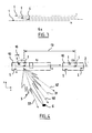
- the first embodiment of the invention considers a train of N Monostatic SAR as shown in Figure 4.
- Figure 4 shows that the general formation of Figure 3 can be equivalent to a large SAR 10 grouping together N SAR 1.
- the N SAR satellites 1 fly on the same orbital trajectory over a point 6 on the ground given at different times t p .
- the images received by the N SAR 1s are added.
- the resulting image has an energy equal to the sum of energies of each image.
- the addition of the N synthetic antennas can therefore be considered as a first addition of N samples from SAR 1 different and previously corrected, then a second addition composite samples on the orbital arc 3.
- the corrected composite sample is equivalent to the sample provided by a simple array of antennas whose N elements are the antennas of N SAR located at N sampling points.
- the network adapts automatically directly and gives a beam 5 directed towards the target 6.
- the meaning of a network pattern and its ambiguities seen by target 6 only applies if network elements transmit the same signal samples.
- the separation between network elements should be equal to the distance that separates two SAR 1s which transmit the same sample at the same time or at different times.
- the distance between two elements is called synchronization distance. It is referenced by 16 in FIG. 4.
- the geometry of the network can even vary along the arc and we can even forget the classic SAR model with a moving antenna regularly.
- this jump requires that the length of the synthetic antenna either of a length equal to a synchronization length, and either by therefore a multiple of the length of recurrence along the orbit.
- sampling interval of a SAR p0 is called “section”, and PRF pulse repetition frequency, or frequency sampling.
- the length of the section is equal to V / PRF. As indicated previously the length of the antenna is at least two sections
- the ambiguity k is received by a network of N elements in function of a difference in A / R distance between consecutive elements, which is a part of k ⁇ , because the spacing of the elements is a part of V / PRF.
- the distribution of the separations between the elements is random and the N contributions of each ambiguity are added in a non coherent, while the N contributions of the processed pixel are added consistently. With the improvement of N of SNR, there is a N improvement in ambiguity protection.
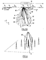
- the second embodiment aims to take advantage of the reduction of the level of ambiguities to authorize their entry into detection beams, and thus allow an improvement in the factor of deserves at the same time as a reduction in the surface of the antenna.
- FIGS. 5A and 5B show that one can first of all carry out a precise spacing of SAR (modulo V / PRF).
- the second embodiment has as main advantage a multiplication of the merit factor and a dilution of the surface stress antenna on all N antennas made N times smaller.
- the distance 12 between the SARs in the equivalent network is now fixed and equal to V / NPRF, that is to say that the real spacing between a satellite and each of the p others at the time of transmission of the same signal sample (and therefore not at the same time because the SARs are not necessarily synchronized) is equal to KV / PRF + p V / NPRF with K indeterminate and p an integer,
- the superimposition of N samples constitutes a single synthetic antenna whose sampling interval is reduced by N.
- the spacing of ambiguities is therefore increased by N and the actual antenna length 1 can therefore be reduced by N without impact on ambiguity, thereby improving resolution by N.
- the network is equivalent to a single continuous antenna with a length L equal to 2V / PRF as shown in Figure 5B, whose beam is automatically slaved to the processed pixel.
- the servo ensures a time of illumination and consequently a resolution equivalent to an antenna N times shorter.
- the PRF and in consequently the swath are unchanged.
- ambiguities are still present, especially in ghost lobes 70. They are spaced apart by angular deviations ⁇ NPRF / 2V and modulated by the antenna diagram real formed by lobe 4 and its side lobes 40.
- the result ambiguity is equivalent to what has already been presented previously: only the ambiguities of a multiple of N are present and give a total level unchanged when the actual antenna pattern is enlarged by one factor N.
- N 2 the level of the elementary sample collected by each antenna both for the useful signal of the target and its ambiguous contribution.
- N of the SNR the improvement by N of the SNR, the latter is still N times lower than that available on each SAR with the antenna size and the original merit factor.
- Another way to realize the invention is to consider a shape spread spectrum wave. This allows a multiplication of the merit factor and an antenna area constraint distribution.
- Figures 6 and 7A and 7B show a comparison of autocorrelation functions (time / frequency) which can also be called distance / doppler ambiguity functions of impulse waves and waves that are considered in the third embodiment.
- Figure 6 shows the classic autocorrelation function of a impulse wave. Spectrum correlation peaks are distributed regularly. To avoid bad reception, the main lobe of detection 4 should only cover the peak.
- Figure 6 shows that the same ambiguity energy is concentrated on a grid of precisely separated peaks without pedestal in the case of a pulse signal.
- V ground speed
- r az azimuth resolution
- S swath.
- Figure 7B shows the same spectrum shape, but it appears when the original signal is periodic with period Te.
- the energy of pedestal is the same but is concentrated on a comb of lines spaced a distance equal to 1 / Te.
- the addition is consistent for the N contributions from the processed pixel (or correlated) then that it is inconsistent for the N contributions from one any of the other pixels.
- the antenna area can be reduced by N for protection unchanged against ambiguity, and for an advantage of N on resolution or on the swath, and anyway on the merit factor.
- N 'among the N SARs use the same waveform and the N' waveforms are synchronized on the orbital arc (the same sample for a given location but for a different time), the N elements of the network model are superimposed. The N 'pixel contributions processed and the N 'contributions of each of the other pixels are added consistently.
- N 'SAR always brings an improvement of the SNR but no improvement in ambiguity.
- N 'SAR are not synchronized on the orbital arc
- This network can be larger than the synthetic antenna.
- this flying network passing along the synthetic antenna and adding the signals of the elements only during the time they are present in the synthetic antenna. This overflight duration is divided into time sequences s i delimited by the entry or exit of an element.
- Each time sequence is associated with a fully network inside the synthetic antenna as shown in Figure 10 and which is a portion of the network N '. All time sequences with a unique network of elements contribute to the combination of N SAR with a signal whose waveform is not correlated with any of the other N SAR.
- Two of the modes of realization use conventional impulse waves.
- the third embodiment uses a spread spectrum signal.
- N SARs do not fly exactly on the same orbital arc in a terrestrial frame of reference and do not exactly respect the assignment of relative position, if any, along the orbital arc.
- N SAR trajectory are randomly distributed in a tube with a width of ⁇ (3 ⁇ ).
- the width of the tube is referenced by 100 in FIG. 8.
- N satellites use real polar orbits with identical parameters, with the exception of ascending nodes and anomalies which have deviations ⁇ and ⁇ a and verify relationships special.
- Ts and Te are the rotation periods of the satellite and the earth respectively.
- R is the radius of the earth.
- the vector formed by two elements of the equivalent network considered in the middle of the synthetic antenna has 3 components:
- One is along the velocity vector and is corrected in terms delay deviation from the pixel processed by the correction of SAR treatment.
- the third is orthogonal to both the velocity vector and the line and is called the interferometric base.
- the second component taken alone provides a phase difference between the outputs of common synthetic antennas on a part significant swath that can be easily identified by averaging and eliminated.
- this first operating condition is that of the InSAR (interferometry transverse to the trace) and is presented as being directly linked to the distance resolution. Under these conditions, the two SAR must be located in the 3dB opening of the equivalent antenna constituted by the distance resolution.
- this first constraint does not really limit the scope of the embodiments.
- the base for a resolution of 1m, a range of 600km at an incidence of 20 °, the base must be smaller than 10 km in X-band and 120 km in L-band
- Figure 8 provides the phase difference sensitivity versus accuracy knowledge of the relief and the interferometric base.
- corrections are made for each of the N SARs relative to a reference and virtual trajectory at the center of the tube.
- the interferometric bases with respect to this reference trajectory are random, with a zero mean value and a standard deviation equal to ( ⁇ / 6 2 )
- the tube width (3 ⁇ ) must be less than 90m to limit the statistical effect on power to 0.5dB. This belongs state of the art of formation flight.
- the knowledge error ⁇ B orth on the interferometric base length provides a phase correction error 4 ⁇ B orth h max Sin (i) Dist ⁇ if h max is the height dynamics of the terrain in the image. Assuming that h max is less than 1000 m, this error can be made negligible if ⁇ B orth is less than 10 cm. This precision can be easily obtained with a differential GPS or Doris.
- the reduction in ambiguity is based on the fact that the N contributions of ambiguity k are not consistent when the contributions from of the processed pixel are made consistent by processing and corrections interferometric. Random spacing along the path already introduced sufficient randomness between ambiguous contribution paths and the tube width does not matter. There are no width constraints tube but those related to the correct interferometric correction.
- SAR SAR samples are not interleaved regularly as described in the paragraph on the second embodiment.
- phase standard deviation of the N contributions is k ⁇ when the standard deviation of the sampling error is ( ⁇ / 2 ⁇ ) V / PRF.
- the complex summation of the N contributions of ambiguity k provides a sum of N vectors regularly distributed in phase and whose modulus (positive or negative) is random with the standard deviation k ⁇ (for de small values of k ⁇ ) if 1 is the modulus of the contribution.
- the residual part of the power received from ambiguity k is Nk 2 ⁇ 2 .
- the power on the processed pixel is increased by N 2 , consequently, the residual protection on the ambiguity k is k 2 ⁇ 2 / N.
- the first two ambiguities are near the first zeros of the beam when the real antenna is in the middle of the antenna synthetic.
- the fact that a form of network does not cancel the ambiguity generated in the shape of the actual antenna when the merit factor is increased by N is an additional ambiguity compared to the usual SAR.
- the residual protection in the form of network should be better than -30dB.
- the complex cancellation leaves a residual part of the power received from the ambiguity k of value N ⁇ k 2 and a residual protection from the ambiguity ⁇ k 2 / N.
- the total residual protection against the 2 (N-1) ambiguities is (2/9) ⁇ sin ( i ) dist ⁇ 2 ⁇ 2 H (N-1) / N ⁇ 2 H being the quadratic mean of the altitude deviations of the first 2 (N-1) ambiguities on each side (located towards the front and towards the rear) of the processed pixel considered for the interferometric correction.
- the spacing between the two satellites must be: (2K + 1) V / 2PRF.
- the maximum sampling error is +/- 3.5cm and is eliminated by a relative PRF setting of +/- 3.5 10 -5 if the distance between the satellites is 1 km.
- sampling constraint is based solely on the accuracy of the distance measurement of the order of 1 cm that can be obtained, when the two satellites are visible, with differential GPS or any RF distance measurement system if both satellites are visible. Practical aspects of trains with visibility SAR will be considered later.
- the tube width constraint and the regularity constraints of previously presented can be mitigated as there is no that only one of the two ambiguities at any time inside the opening of 3 dB. It is possible to make a correction linearly variable interferometric based on the altitude of ambiguity forward at the start of the synthetic antenna and on the altitude of ambiguity backwards at the end.
- the interest of a spread spectrum wave is related to the fact that the ambiguities are found at all points and take advantage of the non-coherent addition since the waves are not correlated over the length of the synthetic antenna or insofar as the distances from resynchronization are random at the scale of the recurrence length and that the synthetic antenna is a multiple of the recurrence.
- each antenna receives N signals and realizes N images which cannot be separated except in using appropriate waveforms.
- each pair formed by a transmitter and a receiver corresponds from the point of view of the phase return (or distance) to an equivalent T / R antenna located at the midpoint between the transmitter and the receiver. If the transmitter also receives, the equivalent T / R is the actual T / R. The length 15 is therefore equal to half the length d N.
- All N antennas must look at the same area of the ground illuminated by the transmitting antenna.
- All synthetic antennas equivalents start and end at the same time but are offset compared to those of the T / R by half the distance between the T and each A.
- the SAR combination can only be performed in the game in overlap of equivalent synthetic antennas and length overall is accordingly reduced by the virtual training length or half the actual training length. This means that the length training should be small compared to the length of the antenna synthetic.
- the transmission signal is added coherently N times.
- the SNR of the combination of N SAR is the same as for an N T / R train without visibility. All the advantages of concept of a standard blind train apply here as well, but the total transmit power is reduced by N.
- the distances are much smaller than the length of the antenna synthetic. So the advantages of the train require a periodic signal and the equivalent T / R must be distributed randomly over the recurrence length, i.e. the actual satellites must be distributed randomly over twice the length of the recurrence.
- the SAR can directly receive the signal transmitted at much higher levels higher than the effective echo.
- the antenna insulations must at least avoid saturation of the receiver.
- the stress is released by more than 10dB by the spread spectrum, since the transmission is continuous instead of being concentrated on peaks representing less than a tenth of the time.
- the signal direct is spread over the entire image with a reduction factor of 1 / 4BT as shown in Figures 7A and 7B.
- the reduction is typically equal to -80dB. Such a reduction significantly helps compatibility.
- the distance spread is very low made of the weak mismatch of the distance correlation and corresponds in Doppler at T PRF pixels in Doppler, which corresponds approximately to approximately - 30dB.
- the impulse signals can cancel completely this problem, including saturation, by rejecting the direct signal through the synchronization, at the cost of additional constraints on the synchronization and duty cycle.
- each of the SARs in the considered SAR train previously is transmitter and receiver, and that spectrum waveforms spread out are distinct and uncorrelated.
- Each transmitting SAR controls one SAR train.
- the SNR is improved by N, or the factor of merit is further increased by N at the cost of further degradation of N of the SNR.
- the first option may be the logical outcome of the concept SAR train because it leads to an improvement in N of the merit factor with an unchanged SNR. But the invention allows all kinds of variations at each of the two train levels, SAR train and train train.
Landscapes
- Engineering & Computer Science (AREA)
- Remote Sensing (AREA)
- Radar, Positioning & Navigation (AREA)
- Physics & Mathematics (AREA)
- Computer Networks & Wireless Communication (AREA)
- General Physics & Mathematics (AREA)
- Electromagnetism (AREA)
- Radar Systems Or Details Thereof (AREA)
Abstract
Description
ou reçoit un signal venant de la cible 6. Ainsi, chaque trait point milieu de la position du SAR 1 est distant du précédent ou du suivant d'une distance 11 égale à V/PRF, où V est la vitesse de déplacement du SAR 1, et PRF est le « Pulse Répétition Frequency » selon la terminologie anglo-saxonne généralement utilisée, ou fréquence de répétition d'impulsion.
- plusieurs paires utilisent un même émetteur ;
- les échantillons des radars sont émis de manière périodique et en ce que entre deux positions du point milieu d'une paire donnée, les positions étant prises aux moments milieux entre émission et réception de l'échantillon, correspondant à deux échantillons successifs pour une même paire, d'autres positions de points milieux correspondant à des échantillons d'autres paires se trouvent répartie de manière périodique ;
- on asservit la période de répétition des échantillons de l'émetteur à (2K+1)V/2D, où V est la vitesse linéaire de déplacement dans le repère local, K est un entier quelconque et D est la mesure de la distance entre deux points milieux de deux paires ;
- on établit la mesure D à l'aide d'un système de télémétrie directe entre les deux récepteurs des deux paires considérées ;
- pour un groupe d'au moins deux paires, le signal est émis et reçu de manière continue sur au moins une partie du tronçon, et comporte une fonction d'autocorrélation étalée en temps et en fréquence et à bas niveau par rapport au pic central ;
- on module le signal en phase entre Pi et -Pi selon une série binaire aléatoire, le signal étant une fréquence pure ;
- on utilise un signal continu périodique avec la même série de signal pour toutes les paires du groupe et une période sensiblement identique, et en ce que entre les deux positions du point milieu d'une même paire correspondant à deux émissions/réceptions successives d'un même élément de la série du signal continu se trouvent répartis aléatoirement les points milieux (N') des autres paires correspondant à l'émission/réception du même élément de la série ;
- la longueur du tronçon est un multiple de la distance entre les deux positions du point milieu d'une même paire correspondant à deux émissions/réceptions successives d'un même élément de la série du signal ;
- on utilise pour le signal continu des formes d'onde décorrélées entre les paires ;
- on utilise plusieurs émetteurs, les paires partageant un même émetteur formant un même groupe, et en ce que les signaux de groupes distincts sont décorrélés d'un groupe à l'autre ;
- on utilise pour le signal continu des formes d'onde décorrélées entre les paires.
- la figure 1, déjà commentée, représente une vue schématique du fonctionnement d'un SAR selon l'état de la technique ;
- la figure 2, déjà commentée, représente une vue schématique de l'équivalent d'un émetteur et d'un récepteur à un SAR émetteur-récepteur ;
- la figure 3 est une représentation schématique d'une formation de N SAR ;
- la figure 4 est une représentation schématique du principe général de la superposition des SAR selon deux directions ;
- les figures 5A et 5B sont des représentations schématiques de principe de fonctionnement d'un premier mode de réalisation de l'invention, qui constitue une amélioration de ce qui est représenté à la figure 4 ;
- La figure 6 représente la fonction d'ambiguïté classique d'une forme d'onde impulsionnelle ;
- La figure 7A représente la fonction d'ambiguïté classique d'une forme d'onde à spectre étalé ;
- La figure 7B représente la fonction d'ambiguïté d'une forme d'onde périodique à spectre étalé ;
- la figure 8 représente une déviation de phase par rapport à la connaissance du relief ;
- la figure 9 représente un train de N satellites (N-1 récepteurs seulement) ; et
- la figure 10 montre schématiquement la répartition de N' SAR dans un tronçon de cohérence.
k λ PRF/2V par rapport à la verticale.
- une amélioration de N du facteur de mérite soit par la résolution soit par la fauchée, soit par un panachage des deux.
- une réduction de N de la taille d'antenne ou en d'autres termes, une répartition d'une aire d'antenne totale minimale inchangée en N plus petites parties.
- une dégradation de N du SNR
- une augmentation de N du volume de données de SAR, entièrement justifiée par l'augmentation du facteur de mérite.
V = vitesse au sol ; raz = résolution de l'azimut ; rrg = résolution de portée = C/(2 sin(i) B) et S = la fauchée.
- pi0 très proche de 1. Ceci signifie que la distance de synchronisation entre deux éléments consécutifs doit être à peu près de la même longueur que l'antenne synthétique. Ceci est en fait équivalent au cas observé précédemment, où les formes d'ondes vues le long des antennes synthétiques sont toutes distinctes.
- les N' formes d'ondes sont périodiques et désynchronisées de façon aléatoire, la longueur de récurrence de l'onde étant une fraction entière 1/p de la longueur de l'antenne synthétique. Dans ce cas, l'énergie ambiguë est concentrée dans un peigne de lignes Doppler espacées de p pixels d'azimut comme représenté à la figure 7B. Le réseau N' est réparti aléatoirement le long de la récurrence référencée par 11 égale à V multipliée par la période à la figure 10 et produit une sommation non cohérente entre ces éléments pour des déviations supérieures à p pixels, c'est-à-dire pour toute l'énergie ambiguë. Puisque p est un entier, la même propriété du réseau N' peut être considérée tout au long de l'antenne synthétique, car un élément sortant peut être remplacé par le même élément lorsqu'il a été entré. Si p est non entier mais plus grand que 1, on peut obtenir le même avantage du facteur N' à condition que l'on restreigne la longueur synthétique à un multiple de la longueur de récurrence.
R Cos(L) ΔΩ.
-R Cos(L) Ts Δa/Te.
Claims (14)
- Procédé de traitement de signal et de guidage de plusieurs instruments comportant des moyens (1) formant radars à synthèse d'ouverture pour l'observation d'une cible (6), les instruments comportant au moins une paire formée d'un émetteur et d'un récepteur, caractérisé en ce qu'on répète l'addition, corrigée des différences de trajet A/R à la cible, en mode complexe des échantillons issus d'une pluralité de paires se différenciant chacune par leur émetteur et/ou leur récepteur, l'ensemble des additions étant effectué sur des paires dont le point milieu est sensiblement situé, dans un repère local lié à la cible et au moment de l'addition corrigée, sur un même tronçon (13) de trajectoire correspondant sensiblement à la longueur de l'antenne synthétique formée par les radars (1).
- Procédé selon la revendication 1, caractérisé en ce que plusieurs paires utilisent un même émetteur (T/R1 ).
- Procédé selon l'une des revendications 1 ou 2, caractérisé en ce que les échantillons des radars (1 ) sont émis de manière périodique et en ce que entre deux positions du point milieu d'une paire donnée, les positions étant prises aux moments milieux entre émission et réception de l'échantillon, correspondant à deux échantillons successifs pour une même paire, d'autres positions de points milieux correspondant à des échantillons d'autres paires se trouvent répartie de manière périodique.
- Procédé selon la revendication 3, caractérisé en ce qu'on asservit la période de répétition des échantillons de l'émetteur à (2K+1)V/2D, où V est la vitesse linéaire de déplacement des radars (1) dans le repère local, K est un entier quelconque et D est la mesure de la distance entre deux points milieux de deux paires.
- Procédé selon la revendication 4, caractérisé en ce qu'on établit la mesure D à l'aide d'un système de télémétrie directe entre les deux récepteurs (1 ) des deux paires considérées.
- Procédé selon la revendication 1, caractérisé en ce que pour un groupe d'au moins deux paires, le signal est émis et reçu de manière continue sur au moins une partie du tronçon, et comporte une fonction d'autocorrélation étalée en temps et en fréquence et à bas niveau par rapport au pic central.
- Procédé selon la revendication 6, caractérisé en ce qu'on module le signal en phase entre Pi et -Pi selon une série binaire aléatoire, le signal étant une fréquence pure.
- Procédé selon l'une des revendications 6 à 7, caractérisé en ce qu'on utilise un signal continu périodique avec la même série de signal pour toutes les paires du groupe et une période sensiblement identique, et en ce que entre les deux positions du point milieu d'une même paire correspondant à deux émissions/réceptions successives d'un même élément de la série du signal continu se trouvent répartis aléatoirement les points milieux des autres paires correspondant à l'émission/réception du même élément de la série.
- Procédé selon la revendication 8, caractérisé en ce que la longueur du tronçon (13) est un multiple de la distance (11) entre les deux positions du point milieu d'une même paire correspondant à deux émissions/réceptions successives d'un même élément de la série du signal.
- Procédé selon l'une des revendications 6 à 7, caractérisé en ce qu'on utilise pour le signal continu des formes d'onde décorrélées entre les paires.
- Procédé selon l'une des revendications 6 à 10 en combinaison avec la revendication 2, caractérisé en ce qu'on utilise plusieurs émetteurs, les paires partageant un même émetteur formant un même groupe, et en ce que les signaux de groupes distincts sont décorrélés d'un groupe à l'autre.
- Ensemble de plusieurs instruments comportant des moyens (1) formant radars à synthèse d'ouverture pour l'observation d'une cible (6), comportant au moins une paire formée d'un émetteur et d'un récepteur, caractérisé en ce qu'il comporte une pluralité de paires et des moyens aptes à effectuer l'addition, corrigée des différences de trajet A/R à la cible, en mode complexe des échantillons issus d'une pluralité de paires se différenciant par l'émetteur ou le récepteur, l'ensemble des additions étant effectué sur des paires dont le point milieu est sensiblement situé, dans un repère local lié à la cible et au moment de l'addition corrigée, sur un même tronçon (13) de trajectoire correspondant sensiblement à la longueur de l'antenne synthétique formée par les radars (1).
- Ensemble selon la revendication 12, caractérisé en ce que les instruments sont portés par des satellites autour d'un astre.
- Ensemble selon l'unes des revendications 12 à 13, caractérisé en ce qu'il comporte les moyens aptes à mettre en oeuvre le procédé selon l'une des revendications 1 à 11.
Applications Claiming Priority (4)
| Application Number | Priority Date | Filing Date | Title |
|---|---|---|---|
| FR0206776 | 2002-06-03 | ||
| FR0206776A FR2840474A1 (fr) | 2002-06-03 | 2002-06-03 | Formations orientees le long du trajet de satellites sar |
| FR0213440A FR2840411B1 (fr) | 2002-06-03 | 2002-10-28 | Formations orientees le long du trajet de satellites sar |
| FR0213440 | 2002-10-28 |
Publications (2)
| Publication Number | Publication Date |
|---|---|
| EP1369704A1 true EP1369704A1 (fr) | 2003-12-10 |
| EP1369704B1 EP1369704B1 (fr) | 2012-11-28 |
Family
ID=29551394
Family Applications (1)
| Application Number | Title | Priority Date | Filing Date |
|---|---|---|---|
| EP03291323A Expired - Lifetime EP1369704B1 (fr) | 2002-06-03 | 2003-06-03 | Formations orientées le long du trajet de satellites SAR |
Country Status (2)
| Country | Link |
|---|---|
| EP (1) | EP1369704B1 (fr) |
| FR (1) | FR2840411B1 (fr) |
Cited By (13)
| Publication number | Priority date | Publication date | Assignee | Title |
|---|---|---|---|---|
| US7667647B2 (en) | 1999-03-05 | 2010-02-23 | Era Systems Corporation | Extension of aircraft tracking and positive identification from movement areas into non-movement areas |
| US7739167B2 (en) | 1999-03-05 | 2010-06-15 | Era Systems Corporation | Automated management of airport revenues |
| US7777675B2 (en) | 1999-03-05 | 2010-08-17 | Era Systems Corporation | Deployable passive broadband aircraft tracking |
| US7782256B2 (en) | 1999-03-05 | 2010-08-24 | Era Systems Corporation | Enhanced passive coherent location techniques to track and identify UAVs, UCAVs, MAVs, and other objects |
| US7889133B2 (en) | 1999-03-05 | 2011-02-15 | Itt Manufacturing Enterprises, Inc. | Multilateration enhancements for noise and operations management |
| US7908077B2 (en) | 2003-06-10 | 2011-03-15 | Itt Manufacturing Enterprises, Inc. | Land use compatibility planning software |
| US7965227B2 (en) | 2006-05-08 | 2011-06-21 | Era Systems, Inc. | Aircraft tracking using low cost tagging as a discriminator |
| US8072382B2 (en) | 1999-03-05 | 2011-12-06 | Sra International, Inc. | Method and apparatus for ADS-B validation, active and passive multilateration, and elliptical surveillance |
| US8203486B1 (en) | 1999-03-05 | 2012-06-19 | Omnipol A.S. | Transmitter independent techniques to extend the performance of passive coherent location |
| US8446321B2 (en) | 1999-03-05 | 2013-05-21 | Omnipol A.S. | Deployable intelligence and tracking system for homeland security and search and rescue |
| CN109444888A (zh) * | 2018-12-31 | 2019-03-08 | 成都汇蓉国科微系统技术有限公司 | 一种星地前视双基地sar图像区域监视方法及系统 |
| CN115096317A (zh) * | 2022-06-16 | 2022-09-23 | 中国科学院空间应用工程与技术中心 | 一种地月空间dro航天器编队相对导航方法和系统 |
| CN115292805A (zh) * | 2022-07-04 | 2022-11-04 | 上海交通大学 | 基线均匀分布的sar成像多星编队分步解耦设计方法 |
Citations (1)
| Publication number | Priority date | Publication date | Assignee | Title |
|---|---|---|---|---|
| WO1999058997A1 (fr) * | 1998-05-13 | 1999-11-18 | Centre National D'etudes Spatiales | Dispositif d'interferometrie radar |
-
2002
- 2002-10-28 FR FR0213440A patent/FR2840411B1/fr not_active Expired - Fee Related
-
2003
- 2003-06-03 EP EP03291323A patent/EP1369704B1/fr not_active Expired - Lifetime
Patent Citations (1)
| Publication number | Priority date | Publication date | Assignee | Title |
|---|---|---|---|---|
| WO1999058997A1 (fr) * | 1998-05-13 | 1999-11-18 | Centre National D'etudes Spatiales | Dispositif d'interferometrie radar |
Non-Patent Citations (1)
| Title |
|---|
| CHERNIAKOV M ET AL: "SECONDARY APPLICATIONS OF WIRELESS TECHNOLOGY (SAWT): THE CONCEPT", 2000 EUROPEAN CONFERENCE ON WIRELESS TECHNOLOGY CONFERENCE PROCEEDINGS. ECWT 2000. PARIS, OCT. 5 - 6, 2000, EUROPEAN CONFERENCE ON WIRELESS TECHNOLOGY. ECWT, LONDON: CMP, GB, 5 October 2000 (2000-10-05), pages 305 - 309, XP001060857, ISBN: 0-86213-217-7 * |
Cited By (13)
| Publication number | Priority date | Publication date | Assignee | Title |
|---|---|---|---|---|
| US8446321B2 (en) | 1999-03-05 | 2013-05-21 | Omnipol A.S. | Deployable intelligence and tracking system for homeland security and search and rescue |
| US7739167B2 (en) | 1999-03-05 | 2010-06-15 | Era Systems Corporation | Automated management of airport revenues |
| US7777675B2 (en) | 1999-03-05 | 2010-08-17 | Era Systems Corporation | Deployable passive broadband aircraft tracking |
| US7782256B2 (en) | 1999-03-05 | 2010-08-24 | Era Systems Corporation | Enhanced passive coherent location techniques to track and identify UAVs, UCAVs, MAVs, and other objects |
| US7889133B2 (en) | 1999-03-05 | 2011-02-15 | Itt Manufacturing Enterprises, Inc. | Multilateration enhancements for noise and operations management |
| US8072382B2 (en) | 1999-03-05 | 2011-12-06 | Sra International, Inc. | Method and apparatus for ADS-B validation, active and passive multilateration, and elliptical surveillance |
| US8203486B1 (en) | 1999-03-05 | 2012-06-19 | Omnipol A.S. | Transmitter independent techniques to extend the performance of passive coherent location |
| US7667647B2 (en) | 1999-03-05 | 2010-02-23 | Era Systems Corporation | Extension of aircraft tracking and positive identification from movement areas into non-movement areas |
| US7908077B2 (en) | 2003-06-10 | 2011-03-15 | Itt Manufacturing Enterprises, Inc. | Land use compatibility planning software |
| US7965227B2 (en) | 2006-05-08 | 2011-06-21 | Era Systems, Inc. | Aircraft tracking using low cost tagging as a discriminator |
| CN109444888A (zh) * | 2018-12-31 | 2019-03-08 | 成都汇蓉国科微系统技术有限公司 | 一种星地前视双基地sar图像区域监视方法及系统 |
| CN115096317A (zh) * | 2022-06-16 | 2022-09-23 | 中国科学院空间应用工程与技术中心 | 一种地月空间dro航天器编队相对导航方法和系统 |
| CN115292805A (zh) * | 2022-07-04 | 2022-11-04 | 上海交通大学 | 基线均匀分布的sar成像多星编队分步解耦设计方法 |
Also Published As
| Publication number | Publication date |
|---|---|
| EP1369704B1 (fr) | 2012-11-28 |
| FR2840411A1 (fr) | 2003-12-05 |
| FR2840411B1 (fr) | 2004-08-27 |
Similar Documents
| Publication | Publication Date | Title |
|---|---|---|
| EP1369704B1 (fr) | Formations orientées le long du trajet de satellites SAR | |
| EP0415818B1 (fr) | Commande de pointage pour système d'antenne à balayage électronique et formation de faisceau par le calcul | |
| EP2674783B1 (fr) | Récepteur de signaux satellitaires servant à la localisation | |
| EP2574957B1 (fr) | Procédé d'estimation de la fréquence doppler non ambigue d'une cible mobile, notamment marine, et radar mettant en oeuvre le procédé | |
| FR2742612A1 (fr) | Procede et circuit de reception de signaux de positionnement par satellites avec elimination des erreurs de multitrajets | |
| EP0322005B1 (fr) | Senseur radioélectrique pour l'établissement d'une carte radioélectrique d'un site | |
| EP2021826A1 (fr) | Systeme d'imagerie sonar a ouverture synthetique | |
| EP2795812A1 (fr) | Procédé et système de calibration pour l'estimation d'une différence de marche d'un signal cible émis par un engin spatial ou aérien | |
| EP1813957B1 (fr) | Dispositif de contrôle de position(s) relative(s) par analyse de signaux bi-fréquences, pour un engin spatial d'un groupe d'engins spatiaux en formation | |
| EP2469299A1 (fr) | Procédé d'amélioration d'images acquises au moyen d'un radar à ouverture synthétique | |
| EP0852734B1 (fr) | Procede et dispositif de geodesie et/ou d'imagerie par traitement de signaux satellitaires | |
| WO2014128304A1 (fr) | Procédé et système d'estimation de direction d'arrivée d'un signal cible par rapport à un satellite | |
| EP3859882B1 (fr) | Système radioélectrique à réseaux d'antennes multiples et à formes d'onde adaptatives | |
| EP0237404A1 (fr) | Procédé de traitement des signaux somme et différence d'un radar du type monopulse, en vue d'estimer la phase parasite introduite entre ces signaux par les circuits hyperfréquence de formation des voies somme et différence | |
| EP2642319B1 (fr) | Dispositif de réception de signaux de radio-navigation à antennes multiples et asservissement de synchronisation commun | |
| FR2998975A1 (fr) | Procede de filtrage, dans un signal radar, des ambiguites distance par codage d'impulsions et traitement multi-voies | |
| EP2410350A1 (fr) | Dispositif d'antenne à ouverture synthetique d'emission de signaux d'un système de navigation par satellites comprenant une porteuse et des moyens de determination de sa trajectoire | |
| CA2389899C (fr) | Procede de repointage pour antenne reseau a reflecteur | |
| WO2022053452A1 (fr) | Système radar bi-statique ou multi-statique pour la surveillance aérienne avec illumination spatiale | |
| FR2840474A1 (fr) | Formations orientees le long du trajet de satellites sar | |
| FR2604843A1 (fr) | Dispositif de reception d'emissions de radio, de television ou d'echos radar | |
| EP4024613A1 (fr) | Procédé de calibration d'une antenne, pointeur et antenne | |
| EP0684488A1 (fr) | Instrument spatial d'observation laser, et véhicule spatial le comportant | |
| EP1522871B1 (fr) | Radar à formation de voies d'écartométrie synthétiques | |
| EP3904904A1 (fr) | Surveillance de l espace à l aide d'un radar bistatique dont le système récepteur est au moins partiellement embarqué dans un satellite |
Legal Events
| Date | Code | Title | Description |
|---|---|---|---|
| PUAI | Public reference made under article 153(3) epc to a published international application that has entered the european phase |
Free format text: ORIGINAL CODE: 0009012 |
|
| AK | Designated contracting states |
Kind code of ref document: A1 Designated state(s): AT BE BG CH CY CZ DE DK EE ES FI FR GB GR HU IE IT LI LU MC NL PT RO SE SI SK TR |
|
| AX | Request for extension of the european patent |
Extension state: AL LT LV MK |
|
| 17P | Request for examination filed |
Effective date: 20040618 |
|
| AKX | Designation fees paid |
Designated state(s): AT BE BG CH CY CZ DE DK EE ES FI FR GB GR HU IE IT LI LU MC NL PT RO SE SI SK TR |
|
| 17Q | First examination report despatched |
Effective date: 20081202 |
|
| GRAP | Despatch of communication of intention to grant a patent |
Free format text: ORIGINAL CODE: EPIDOSNIGR1 |
|
| GRAS | Grant fee paid |
Free format text: ORIGINAL CODE: EPIDOSNIGR3 |
|
| GRAA | (expected) grant |
Free format text: ORIGINAL CODE: 0009210 |
|
| AK | Designated contracting states |
Kind code of ref document: B1 Designated state(s): AT BE BG CH CY CZ DE DK EE ES FI FR GB GR HU IE IT LI LU MC NL PT RO SE SI SK TR |
|
| REG | Reference to a national code |
Ref country code: GB Ref legal event code: FG4D Free format text: NOT ENGLISH |
|
| REG | Reference to a national code |
Ref country code: CH Ref legal event code: EP |
|
| REG | Reference to a national code |
Ref country code: AT Ref legal event code: REF Ref document number: 586444 Country of ref document: AT Kind code of ref document: T Effective date: 20121215 |
|
| REG | Reference to a national code |
Ref country code: IE Ref legal event code: FG4D Free format text: LANGUAGE OF EP DOCUMENT: FRENCH |
|
| REG | Reference to a national code |
Ref country code: DE Ref legal event code: R096 Ref document number: 60342697 Country of ref document: DE Effective date: 20130124 |
|
| REG | Reference to a national code |
Ref country code: SE Ref legal event code: TRGR |
|
| REG | Reference to a national code |
Ref country code: NL Ref legal event code: T3 |
|
| REG | Reference to a national code |
Ref country code: AT Ref legal event code: MK05 Ref document number: 586444 Country of ref document: AT Kind code of ref document: T Effective date: 20121128 |
|
| PG25 | Lapsed in a contracting state [announced via postgrant information from national office to epo] |
Ref country code: FI Free format text: LAPSE BECAUSE OF FAILURE TO SUBMIT A TRANSLATION OF THE DESCRIPTION OR TO PAY THE FEE WITHIN THE PRESCRIBED TIME-LIMIT Effective date: 20121128 Ref country code: ES Free format text: LAPSE BECAUSE OF FAILURE TO SUBMIT A TRANSLATION OF THE DESCRIPTION OR TO PAY THE FEE WITHIN THE PRESCRIBED TIME-LIMIT Effective date: 20130311 |
|
| PG25 | Lapsed in a contracting state [announced via postgrant information from national office to epo] |
Ref country code: GR Free format text: LAPSE BECAUSE OF FAILURE TO SUBMIT A TRANSLATION OF THE DESCRIPTION OR TO PAY THE FEE WITHIN THE PRESCRIBED TIME-LIMIT Effective date: 20130301 Ref country code: CY Free format text: LAPSE BECAUSE OF FAILURE TO SUBMIT A TRANSLATION OF THE DESCRIPTION OR TO PAY THE FEE WITHIN THE PRESCRIBED TIME-LIMIT Effective date: 20121128 Ref country code: PT Free format text: LAPSE BECAUSE OF FAILURE TO SUBMIT A TRANSLATION OF THE DESCRIPTION OR TO PAY THE FEE WITHIN THE PRESCRIBED TIME-LIMIT Effective date: 20130328 Ref country code: SI Free format text: LAPSE BECAUSE OF FAILURE TO SUBMIT A TRANSLATION OF THE DESCRIPTION OR TO PAY THE FEE WITHIN THE PRESCRIBED TIME-LIMIT Effective date: 20121128 |
|
| PG25 | Lapsed in a contracting state [announced via postgrant information from national office to epo] |
Ref country code: AT Free format text: LAPSE BECAUSE OF FAILURE TO SUBMIT A TRANSLATION OF THE DESCRIPTION OR TO PAY THE FEE WITHIN THE PRESCRIBED TIME-LIMIT Effective date: 20121128 |
|
| PG25 | Lapsed in a contracting state [announced via postgrant information from national office to epo] |
Ref country code: SK Free format text: LAPSE BECAUSE OF FAILURE TO SUBMIT A TRANSLATION OF THE DESCRIPTION OR TO PAY THE FEE WITHIN THE PRESCRIBED TIME-LIMIT Effective date: 20121128 Ref country code: BG Free format text: LAPSE BECAUSE OF FAILURE TO SUBMIT A TRANSLATION OF THE DESCRIPTION OR TO PAY THE FEE WITHIN THE PRESCRIBED TIME-LIMIT Effective date: 20130228 Ref country code: EE Free format text: LAPSE BECAUSE OF FAILURE TO SUBMIT A TRANSLATION OF THE DESCRIPTION OR TO PAY THE FEE WITHIN THE PRESCRIBED TIME-LIMIT Effective date: 20121128 Ref country code: DK Free format text: LAPSE BECAUSE OF FAILURE TO SUBMIT A TRANSLATION OF THE DESCRIPTION OR TO PAY THE FEE WITHIN THE PRESCRIBED TIME-LIMIT Effective date: 20121128 Ref country code: CZ Free format text: LAPSE BECAUSE OF FAILURE TO SUBMIT A TRANSLATION OF THE DESCRIPTION OR TO PAY THE FEE WITHIN THE PRESCRIBED TIME-LIMIT Effective date: 20121128 |
|
| PG25 | Lapsed in a contracting state [announced via postgrant information from national office to epo] |
Ref country code: RO Free format text: LAPSE BECAUSE OF FAILURE TO SUBMIT A TRANSLATION OF THE DESCRIPTION OR TO PAY THE FEE WITHIN THE PRESCRIBED TIME-LIMIT Effective date: 20121128 |
|
| PGFP | Annual fee paid to national office [announced via postgrant information from national office to epo] |
Ref country code: NL Payment date: 20130516 Year of fee payment: 11 |
|
| PLBE | No opposition filed within time limit |
Free format text: ORIGINAL CODE: 0009261 |
|
| STAA | Information on the status of an ep patent application or granted ep patent |
Free format text: STATUS: NO OPPOSITION FILED WITHIN TIME LIMIT |
|
| 26N | No opposition filed |
Effective date: 20130829 |
|
| REG | Reference to a national code |
Ref country code: DE Ref legal event code: R097 Ref document number: 60342697 Country of ref document: DE Effective date: 20130829 |
|
| BERE | Be: lapsed |
Owner name: CENTRE NATIONAL D'ETUDES SPATIALES Effective date: 20130630 |
|
| PG25 | Lapsed in a contracting state [announced via postgrant information from national office to epo] |
Ref country code: MC Free format text: LAPSE BECAUSE OF FAILURE TO SUBMIT A TRANSLATION OF THE DESCRIPTION OR TO PAY THE FEE WITHIN THE PRESCRIBED TIME-LIMIT Effective date: 20121128 Ref country code: SE Free format text: LAPSE BECAUSE OF NON-PAYMENT OF DUE FEES Effective date: 20130604 |
|
| REG | Reference to a national code |
Ref country code: CH Ref legal event code: PL |
|
| REG | Reference to a national code |
Ref country code: SE Ref legal event code: EUG |
|
| GBPC | Gb: european patent ceased through non-payment of renewal fee |
Effective date: 20130603 |
|
| REG | Reference to a national code |
Ref country code: IE Ref legal event code: MM4A |
|
| REG | Reference to a national code |
Ref country code: DE Ref legal event code: R119 Ref document number: 60342697 Country of ref document: DE Effective date: 20140101 |
|
| REG | Reference to a national code |
Ref country code: FR Ref legal event code: ST Effective date: 20140228 |
|
| PG25 | Lapsed in a contracting state [announced via postgrant information from national office to epo] |
Ref country code: BE Free format text: LAPSE BECAUSE OF NON-PAYMENT OF DUE FEES Effective date: 20130630 |
|
| PG25 | Lapsed in a contracting state [announced via postgrant information from national office to epo] |
Ref country code: IE Free format text: LAPSE BECAUSE OF NON-PAYMENT OF DUE FEES Effective date: 20130603 Ref country code: GB Free format text: LAPSE BECAUSE OF NON-PAYMENT OF DUE FEES Effective date: 20130603 Ref country code: LI Free format text: LAPSE BECAUSE OF NON-PAYMENT OF DUE FEES Effective date: 20130630 Ref country code: DE Free format text: LAPSE BECAUSE OF NON-PAYMENT OF DUE FEES Effective date: 20140101 Ref country code: CH Free format text: LAPSE BECAUSE OF NON-PAYMENT OF DUE FEES Effective date: 20130630 |
|
| PG25 | Lapsed in a contracting state [announced via postgrant information from national office to epo] |
Ref country code: IT Free format text: LAPSE BECAUSE OF NON-PAYMENT OF DUE FEES Effective date: 20130603 Ref country code: FR Free format text: LAPSE BECAUSE OF NON-PAYMENT OF DUE FEES Effective date: 20130701 |
|
| REG | Reference to a national code |
Ref country code: NL Ref legal event code: V1 Effective date: 20150101 |
|
| PG25 | Lapsed in a contracting state [announced via postgrant information from national office to epo] |
Ref country code: NL Free format text: LAPSE BECAUSE OF NON-PAYMENT OF DUE FEES Effective date: 20150101 |
|
| PG25 | Lapsed in a contracting state [announced via postgrant information from national office to epo] |
Ref country code: TR Free format text: LAPSE BECAUSE OF FAILURE TO SUBMIT A TRANSLATION OF THE DESCRIPTION OR TO PAY THE FEE WITHIN THE PRESCRIBED TIME-LIMIT Effective date: 20121128 |
|
| PG25 | Lapsed in a contracting state [announced via postgrant information from national office to epo] |
Ref country code: LU Free format text: LAPSE BECAUSE OF NON-PAYMENT OF DUE FEES Effective date: 20130603 Ref country code: HU Free format text: LAPSE BECAUSE OF FAILURE TO SUBMIT A TRANSLATION OF THE DESCRIPTION OR TO PAY THE FEE WITHIN THE PRESCRIBED TIME-LIMIT; INVALID AB INITIO Effective date: 20030603 |