EP1369552B1 - Structural cover for gas turbine engine bolted flanges - Google Patents
Structural cover for gas turbine engine bolted flanges Download PDFInfo
- Publication number
- EP1369552B1 EP1369552B1 EP03252064A EP03252064A EP1369552B1 EP 1369552 B1 EP1369552 B1 EP 1369552B1 EP 03252064 A EP03252064 A EP 03252064A EP 03252064 A EP03252064 A EP 03252064A EP 1369552 B1 EP1369552 B1 EP 1369552B1
- Authority
- EP
- European Patent Office
- Prior art keywords
- cover
- fastener
- gas turbine
- scalloped
- outer perimeter
- Prior art date
- Legal status (The legal status is an assumption and is not a legal conclusion. Google has not performed a legal analysis and makes no representation as to the accuracy of the status listed.)
- Expired - Lifetime
Links
- 238000000034 method Methods 0.000 claims description 6
- 238000004519 manufacturing process Methods 0.000 claims description 5
- 230000008878 coupling Effects 0.000 description 14
- 238000010168 coupling process Methods 0.000 description 14
- 238000005859 coupling reaction Methods 0.000 description 14
- 238000009434 installation Methods 0.000 description 2
- 230000002411 adverse Effects 0.000 description 1
- 238000001816 cooling Methods 0.000 description 1
- 239000000446 fuel Substances 0.000 description 1
- 239000000203 mixture Substances 0.000 description 1
- 238000011144 upstream manufacturing Methods 0.000 description 1
Images

Classifications
-
- F—MECHANICAL ENGINEERING; LIGHTING; HEATING; WEAPONS; BLASTING
- F02—COMBUSTION ENGINES; HOT-GAS OR COMBUSTION-PRODUCT ENGINE PLANTS
- F02C—GAS-TURBINE PLANTS; AIR INTAKES FOR JET-PROPULSION PLANTS; CONTROLLING FUEL SUPPLY IN AIR-BREATHING JET-PROPULSION PLANTS
- F02C7/00—Features, components parts, details or accessories, not provided for in, or of interest apart form groups F02C1/00 - F02C6/00; Air intakes for jet-propulsion plants
- F02C7/22—Fuel supply systems
-
- F—MECHANICAL ENGINEERING; LIGHTING; HEATING; WEAPONS; BLASTING
- F01—MACHINES OR ENGINES IN GENERAL; ENGINE PLANTS IN GENERAL; STEAM ENGINES
- F01D—NON-POSITIVE DISPLACEMENT MACHINES OR ENGINES, e.g. STEAM TURBINES
- F01D11/00—Preventing or minimising internal leakage of working-fluid, e.g. between stages
- F01D11/001—Preventing or minimising internal leakage of working-fluid, e.g. between stages for sealing space between stator blade and rotor
-
- F—MECHANICAL ENGINEERING; LIGHTING; HEATING; WEAPONS; BLASTING
- F01—MACHINES OR ENGINES IN GENERAL; ENGINE PLANTS IN GENERAL; STEAM ENGINES
- F01D—NON-POSITIVE DISPLACEMENT MACHINES OR ENGINES, e.g. STEAM TURBINES
- F01D25/00—Component parts, details, or accessories, not provided for in, or of interest apart from, other groups
- F01D25/08—Cooling; Heating; Heat-insulation
- F01D25/12—Cooling
-
- F—MECHANICAL ENGINEERING; LIGHTING; HEATING; WEAPONS; BLASTING
- F01—MACHINES OR ENGINES IN GENERAL; ENGINE PLANTS IN GENERAL; STEAM ENGINES
- F01D—NON-POSITIVE DISPLACEMENT MACHINES OR ENGINES, e.g. STEAM TURBINES
- F01D5/00—Blades; Blade-carrying members; Heating, heat-insulating, cooling or antivibration means on the blades or the members
- F01D5/02—Blade-carrying members, e.g. rotors
- F01D5/08—Heating, heat-insulating or cooling means
-
- F—MECHANICAL ENGINEERING; LIGHTING; HEATING; WEAPONS; BLASTING
- F01—MACHINES OR ENGINES IN GENERAL; ENGINE PLANTS IN GENERAL; STEAM ENGINES
- F01D—NON-POSITIVE DISPLACEMENT MACHINES OR ENGINES, e.g. STEAM TURBINES
- F01D9/00—Stators
-
- F—MECHANICAL ENGINEERING; LIGHTING; HEATING; WEAPONS; BLASTING
- F01—MACHINES OR ENGINES IN GENERAL; ENGINE PLANTS IN GENERAL; STEAM ENGINES
- F01D—NON-POSITIVE DISPLACEMENT MACHINES OR ENGINES, e.g. STEAM TURBINES
- F01D9/00—Stators
- F01D9/02—Nozzles; Nozzle boxes; Stator blades; Guide conduits, e.g. individual nozzles
- F01D9/04—Nozzles; Nozzle boxes; Stator blades; Guide conduits, e.g. individual nozzles forming ring or sector
-
- F—MECHANICAL ENGINEERING; LIGHTING; HEATING; WEAPONS; BLASTING
- F02—COMBUSTION ENGINES; HOT-GAS OR COMBUSTION-PRODUCT ENGINE PLANTS
- F02C—GAS-TURBINE PLANTS; AIR INTAKES FOR JET-PROPULSION PLANTS; CONTROLLING FUEL SUPPLY IN AIR-BREATHING JET-PROPULSION PLANTS
- F02C7/00—Features, components parts, details or accessories, not provided for in, or of interest apart form groups F02C1/00 - F02C6/00; Air intakes for jet-propulsion plants
- F02C7/20—Mounting or supporting of plant; Accommodating heat expansion or creep
-
- F—MECHANICAL ENGINEERING; LIGHTING; HEATING; WEAPONS; BLASTING
- F23—COMBUSTION APPARATUS; COMBUSTION PROCESSES
- F23R—GENERATING COMBUSTION PRODUCTS OF HIGH PRESSURE OR HIGH VELOCITY, e.g. GAS-TURBINE COMBUSTION CHAMBERS
- F23R3/00—Continuous combustion chambers using liquid or gaseous fuel
- F23R3/28—Continuous combustion chambers using liquid or gaseous fuel characterised by the fuel supply
- F23R3/286—Continuous combustion chambers using liquid or gaseous fuel characterised by the fuel supply having fuel-air premixing devices
-
- F—MECHANICAL ENGINEERING; LIGHTING; HEATING; WEAPONS; BLASTING
- F23—COMBUSTION APPARATUS; COMBUSTION PROCESSES
- F23R—GENERATING COMBUSTION PRODUCTS OF HIGH PRESSURE OR HIGH VELOCITY, e.g. GAS-TURBINE COMBUSTION CHAMBERS
- F23R3/00—Continuous combustion chambers using liquid or gaseous fuel
- F23R3/28—Continuous combustion chambers using liquid or gaseous fuel characterised by the fuel supply
- F23R3/34—Feeding into different combustion zones
- F23R3/343—Pilot flames, i.e. fuel nozzles or injectors using only a very small proportion of the total fuel to insure continuous combustion
-
- F—MECHANICAL ENGINEERING; LIGHTING; HEATING; WEAPONS; BLASTING
- F05—INDEXING SCHEMES RELATING TO ENGINES OR PUMPS IN VARIOUS SUBCLASSES OF CLASSES F01-F04
- F05D—INDEXING SCHEME FOR ASPECTS RELATING TO NON-POSITIVE-DISPLACEMENT MACHINES OR ENGINES, GAS-TURBINES OR JET-PROPULSION PLANTS
- F05D2240/00—Components
- F05D2240/10—Stators
- F05D2240/14—Casings or housings protecting or supporting assemblies within
-
- F—MECHANICAL ENGINEERING; LIGHTING; HEATING; WEAPONS; BLASTING
- F05—INDEXING SCHEMES RELATING TO ENGINES OR PUMPS IN VARIOUS SUBCLASSES OF CLASSES F01-F04
- F05D—INDEXING SCHEME FOR ASPECTS RELATING TO NON-POSITIVE-DISPLACEMENT MACHINES OR ENGINES, GAS-TURBINES OR JET-PROPULSION PLANTS
- F05D2260/00—Function
- F05D2260/97—Reducing windage losses
-
- F—MECHANICAL ENGINEERING; LIGHTING; HEATING; WEAPONS; BLASTING
- F23—COMBUSTION APPARATUS; COMBUSTION PROCESSES
- F23D—BURNERS
- F23D2900/00—Special features of, or arrangements for burners using fluid fuels or solid fuels suspended in a carrier gas
- F23D2900/00018—Means for protecting parts of the burner, e.g. ceramic lining outside of the flame tube
-
- Y—GENERAL TAGGING OF NEW TECHNOLOGICAL DEVELOPMENTS; GENERAL TAGGING OF CROSS-SECTIONAL TECHNOLOGIES SPANNING OVER SEVERAL SECTIONS OF THE IPC; TECHNICAL SUBJECTS COVERED BY FORMER USPC CROSS-REFERENCE ART COLLECTIONS [XRACs] AND DIGESTS
- Y02—TECHNOLOGIES OR APPLICATIONS FOR MITIGATION OR ADAPTATION AGAINST CLIMATE CHANGE
- Y02T—CLIMATE CHANGE MITIGATION TECHNOLOGIES RELATED TO TRANSPORTATION
- Y02T50/00—Aeronautics or air transport
- Y02T50/60—Efficient propulsion technologies, e.g. for aircraft
Definitions
- This invention relates generally to gas turbine engines, and more specifically to structural covers used with gas turbine engine bolted flanges.
- At least some known gas turbine engines include a core engine having, in serial flow arrangement, a high pressure compressor which compresses airflow entering the engine, a combustor which burns a mixture of fuel and air, and a turbine which includes a plurality of rotor blades that extract rotational energy from airflow exiting the combustor.
- At least some known bolted flanges as disclosed in EP 0 926 315 include a separate windage cover which extends over the heads or nuts of the fasteners to facilitate minimizing fastener exposure to the gas flowpath.
- a separate windage cover which extends over the heads or nuts of the fasteners to facilitate minimizing fastener exposure to the gas flowpath.
- longer fasteners and an additional alignment flange must be used in comparison to those bolted flanges which do not include the covers. As such, installing such covers increases overall manufacturing assembly time, parts count, engine weight, and overall manufacturing costs.
- a method for manufacturing a structural cover for a gas turbine engine as in claim 1 is provided.
- a structural cover for a gas turbine engine as in claim 5 is provided.
- a gas turbine including a torrodial structural cover as in claim 8 is provided.
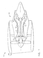
- Figure 1 is a schematic illustration of a gas turbine engine 10 including a fan assembly 12, a high pressure compressor 14, and a combustor 16.
- Engine 10 also includes a high pressure turbine assembly 18 and a low pressure turbine assembly 20.
- Engine 10 has an intake side 28 and an exhaust side 30.
- engine 10 is a CF34 engine commercially available from General Electric Aircraft Engines, Cincinnati, Ohio.
- Airflow from combustor 16 drives turbines 18 and 20, and turbine 20 drives fan assembly 12.
- Turbine 18 drives high pressure compressor 14.
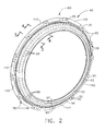
- Figure 2 is a perspective view of a structural cover 40 that may be used with gas turbine engine 10.
- Figure 3 is a cross-sectional view of structural cover 40 taken along line 3-3
- Figure 4 is a cross-sectional view of structural cover 40 taken along line 4-4.
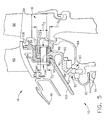
- Figure 5 is a partial cross-sectional view of gas turbine engine 10 including structural cover 40 taken along line 3-3.
- structural cover 40 is a forward outer seal flange and is coupled within engine 10 to high pressure turbine assembly 18 downstream from combustor 16. More specifically, combustor 16 includes a liner 46 that extends downstream to a turbine nozzle 48, such that airflow from combustor 16 is discharged through turbine nozzle 48.
- Structural cover 40 is coupled radially inward from turbine nozzle 48 and upstream from a first stage of high pressure turbine blades 50.
- Structural cover 40 is annular and includes a torrodial body 52 that extends radially between an inner perimeter 54 and an outer perimeter 56. Body 52 also extends axially between a forward side 58 and an aft side 60. Torrodial body 52 is frusto conical, such that when coupled within engine 10, outer perimeter 56 is radially outward from, and axially-downstream from, inner perimeter 54.
- Body 52 includes an integrally-formed windage cover portion 70 and a seal flange portion 72. More specifically windage cover portion 70 extends from inner perimeter 58 to outer perimeter 56, and seal flange portion 72 extends from windage cover portion 70 arcuately along portions 78 of outer perimeter 56.
- Cover inner perimeter 58 is defined by an arcuate lip 80 that extends to a body seal portion 82.
- Body seal portion 82 facilitates forming a seal 83 with a high pressure turbine seal member 84, and extends between lip 80 and a body coupling portion 86.
- cover seal portion 82 when cover 40 is coupled within engine 10, because body 52 is frusto-conical, cover seal portion 82 extends obliquely from lip 80 with respect to an engine centerline axis of symmetry (not shown).
- structural cover seal portion 82 includes a plurality of cooling openings 88 extending therethrough. More specifically, cover coupling portion 86 extends from cover seal portion 82 to body outer perimeter 56 and facilitates coupling structural cover 40 within engine 10. In the exemplary embodiment, cover coupling portion 86 is substantially perpendicular with respect to the engine centerline axis of symmetry.
- a plurality of fastener bosses 90 are spaced circumferentially along body outer perimeter 56 within cover coupling portion 86.
- Each fastener boss 90 includes at least one fastener opening 92 extending therethrough between cover forward side 58 to cover aft side 60. More specifically, openings 92 are sized to receive a fastener 96 therethrough for coupling cover 40 within engine 10.
- openings 92 extend axially through bosses 90 and are substantially parallel to the engine centerline axis of symmetry.
- Adjacent fastener bosses 90 are separated along body outer perimeter 56 by at least one scalloped pocket 110. More specifically, scalloped pockets 110 are spaced circumferentially along body outer perimeter within cover coupling portion 86. Each scalloped pocket 110 is arcuate in shape and extends radially inwardly from cover outer perimeter 56 to a radially inner pocket surface 112. More specifically, each scalloped pocket 110 extends from cover forward side 58 towards cover aft side 60. Accordingly, scalloped pockets 110 do not penetrate cover aft side 60, but instead facilitate reducing an overall weight of structural cover 40, thus facilitating an overall improvement in engine performance.
- Seal flange portion 72 extends from windage cover portion 70 arcuately along portions 78 of outer perimeter 56 and facilitates alignment of cover 40 within engine 10. More specifically, seal flange only extends along outer perimeter 56 adjacent each fastener boss 90, such that each fastener boss 90 defines a portion of seal flange portion 72. Furthermore, because seal flange portion 72 is integrally formed with windage cover portion 70 and bosses 90, a thickness T 1 of seal flange portion 72 does not necessitate an increased length 114 of fastener 96 when cover 40 is coupled within engine 10.
- Seal flange portion 72 includes a recessed opening 120 that facilitates shielding fasteners 96 and retainers 122 coupled to fasteners 96 from the gas flowpath within engine 10.
- Each recessed opening 120 extends from an aft side 60 of each boss 90 towards a forward side 58 of each boss 90.
- each recessed opening 120 has a diameter D 1 which is larger than a D 2 of each fastener opening 92. More specifically, each recessed opening 120 is positioned substantially concentrically with respect to each fastener opening 98.
- Recessed opening diameter D 1 is also larger than an outer diameter D 3 of each fastener retainer 122.
- Boss thickness T 1 is measured between each respective boss forward side 58 and recessed opening 120.
- fasteners 96 are extended through a plurality of engine structural mounting components 106 and into each respective cover fastener opening 92. Fasteners 96 are then extended into recessed openings 120 and retainers 122 are coupled to fasteners 96 to secure cover 40 within engine 10 with respect to engine components 106.
- fasteners 96 are bolts
- retainers 122 are nuts threadably coupled to the bolts. Because cover 40 is integrally formed with seal flange portion 72 and windage cover portion 70, additional flanges are not required for alignment of cover 40 with respect to engine 10, and an additional windage cover is not necessary to facilitate shielding fasteners 96 and retainers 122.
- cover 40 facilitates fasteners 96 having a shorter length 114 than other known covers coupled to the same engine components 106.
- cover 40 is integrally formed with seal flange portion 72 and windage cover portion 70, an overall length of engine 10 is shorter in comparison to known covers including separate seal flanges and windage covers, thus facilitating reducing an overall weight of engine 10.
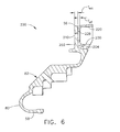
- FIG 6 is a cross-sectional view of a known windage cover 200 (see for example EP 0 926 315 ).
- Windage cover 200 is similar to structural cover 40 (shown in Figures 2 , 3 , 4 , and 5 ) and components in windage cover 200 that are identical to components of structural cover 40 are identified in Figure 6 using the same reference numerals used in Figures 2 , 3 , 4 , and 5 .
- windage cover 200 includes outer and inner perimeters 56 and 58, lip 80, and body seal portion 82.
- Windage cover 200 also includes an annular coupling portion 202 that extends between body seal portion 82 and outer perimeter 56.
- coupling portion 202 extends radially outwardly from seal portion 82 to define a shelf 204 extending between coupling portion 202 and seal portion 82.
- Coupling portion 202 also includes a plurality of openings 210 extending therethrough and spaced circumferentially around windage cover 200 within coupling portion 202.
- Each opening 210 is sized to receive a fastener (not shown) therethrough. More specifically, a seal flange 220 is coupled against windage cover 200 and extends circumferentially adjacent cover shelf 204 such that a plurality of openings 226 extending through flange 220 are substantially concentrically aligned with respect to windage cover openings 210. Flange 220 facilitates maintaining a proper alignment of cover 200 when cover 200 is coupled to engine mounting components 106 within engine 10.
- Seal flange 220 also defines a recessed area 230 that facilitates shielding fasteners and associated coupling retainers (not shown) used to mount cover 200 within engine 10. More specifically, during assembly, the fasteners are extended through the same structural mounting components 106 (shown in Figure 5 ) as fasteners 96 (shown in Figure 5 ), however the fasteners extending through windage cover 200 have a length (not shown) that is longer than fastener length 114 (shown in Figure 5 ). The increased fastener length is necessary to accommodate a thickness T WC of windage cover coupling portion 202 adjacent openings 210 and an increased thickness T SF of an annular seal flange 220 coupled between windage cover 200 and seal flange recessed area 230.
- the above-described structural cover is cost-effective and highly reliable.
- the unitary cover is integrally formed to include a windage cover portion and a seal flange portion, such that fewer assembly parts are required.
- the seal flange portion facilitates shielding the mounting fasteners from the gas turbine engine gas flowpath, and also facilitates proper alignment of the cover during installation.
- the cover is integrally formed, a length of mounting fasteners used is shorter than other known covers coupled to the same engine components.
- the cover includes a plurality of scalloped pockets which reduce an overall weight of the cover in comparison to other known covers coupled to the same engine components. As a result, the integral structural cover facilitates reducing manufacturing costs in a cost-effective and reliable manner.
Landscapes
- Engineering & Computer Science (AREA)
- Mechanical Engineering (AREA)
- General Engineering & Computer Science (AREA)
- Chemical & Material Sciences (AREA)
- Combustion & Propulsion (AREA)
- Turbine Rotor Nozzle Sealing (AREA)
- Details Of Aerials (AREA)
- Structures Of Non-Positive Displacement Pumps (AREA)
Applications Claiming Priority (2)
| Application Number | Priority Date | Filing Date | Title |
|---|---|---|---|
| US164954 | 2002-06-06 | ||
| US10/164,954 US6761034B2 (en) | 2000-12-08 | 2002-06-06 | Structural cover for gas turbine engine bolted flanges |
Publications (3)
| Publication Number | Publication Date |
|---|---|
| EP1369552A2 EP1369552A2 (en) | 2003-12-10 |
| EP1369552A3 EP1369552A3 (en) | 2005-11-16 |
| EP1369552B1 true EP1369552B1 (en) | 2011-06-29 |
Family
ID=29549362
Family Applications (1)
| Application Number | Title | Priority Date | Filing Date |
|---|---|---|---|
| EP03252064A Expired - Lifetime EP1369552B1 (en) | 2002-06-06 | 2003-04-01 | Structural cover for gas turbine engine bolted flanges |
Country Status (4)
| Country | Link |
|---|---|
| US (1) | US6761034B2 (zh) |
| EP (1) | EP1369552B1 (zh) |
| JP (1) | JP4450564B2 (zh) |
| CN (1) | CN100582441C (zh) |
Families Citing this family (37)
| Publication number | Priority date | Publication date | Assignee | Title |
|---|---|---|---|---|
| FR2875270B1 (fr) * | 2004-09-10 | 2006-12-01 | Snecma Moteurs Sa | Retenue des clavettes de centrage des anneaux sous aubes de stator a calage variable d'un moteur a turbine a gaz |
| US7094020B2 (en) * | 2004-09-15 | 2006-08-22 | General Electric Company | Swirl-enhanced aerodynamic fastener shield for turbomachine |
| ITMI20041780A1 (it) * | 2004-09-17 | 2004-12-17 | Nuovo Pignone Spa | Dispositivo di protezione per uno statore di una turbina |
| GB0424883D0 (en) * | 2004-11-11 | 2004-12-15 | Rolls Royce Plc | Seal structure |
| US7909569B2 (en) * | 2005-06-09 | 2011-03-22 | Pratt & Whitney Canada Corp. | Turbine support case and method of manufacturing |
| US7341429B2 (en) * | 2005-11-16 | 2008-03-11 | General Electric Company | Methods and apparatuses for cooling gas turbine engine rotor assemblies |
| JP4764219B2 (ja) * | 2006-03-17 | 2011-08-31 | 三菱重工業株式会社 | ガスタービンのシール構造 |
| US7445424B1 (en) | 2006-04-22 | 2008-11-04 | Florida Turbine Technologies, Inc. | Passive thermostatic bypass flow control for a brush seal application |
| FR2908153B1 (fr) * | 2006-11-07 | 2011-05-13 | Snecma | Dispositif d'accrochage d'un distributeur (8) d'une turbine, turbine les comportant, et moteur d'aeronef en etant equipe |
| FR2935429B1 (fr) * | 2008-08-26 | 2011-11-25 | Snecma | Aubage fixe de turbomachine a masse reduite et turbomachine comportant au moins un tel aubage fixe |
| JP4856257B2 (ja) * | 2010-03-24 | 2012-01-18 | 川崎重工業株式会社 | タービンロータのシール構造 |
| JP2012107580A (ja) * | 2010-11-18 | 2012-06-07 | Toyota Motor Corp | 車両内燃機関の制御装置。 |
| US9664062B2 (en) * | 2011-12-08 | 2017-05-30 | Siemens Energy, Inc. | Gas turbine engine with multiple component exhaust diffuser operating in conjunction with an outer case ambient external cooling system |
| US9353647B2 (en) | 2012-04-27 | 2016-05-31 | General Electric Company | Wide discourager tooth |
| US9567908B2 (en) | 2012-04-27 | 2017-02-14 | General Electric Company | Mitigating vortex pumping effect upstream of oil seal |
| US9133723B2 (en) * | 2012-05-21 | 2015-09-15 | United Technologies Corporation | Shield system for gas turbine engine |
| WO2014051691A1 (en) * | 2012-09-27 | 2014-04-03 | United Technologies Corporation | Buffer airflow to bearing compartment |
| US10329936B2 (en) | 2013-08-07 | 2019-06-25 | United Technologies Corporation | Gas turbine engine aft seal plate geometry |
| US9964037B2 (en) | 2014-02-26 | 2018-05-08 | United Technologies Corporation | Staged heat exchangers for multi-bypass stream gas turbine engines |
| US10443450B2 (en) | 2014-10-24 | 2019-10-15 | United Technologies Corporation | Seal support structure for a circumferential seal of a gas turbine engine |
| US10422238B2 (en) | 2014-12-05 | 2019-09-24 | Rolls-Royce Corporation | Method to pilot using flexible profile |
| US10301957B2 (en) * | 2014-12-17 | 2019-05-28 | United Technologies Corporation | Pinned seal |
| US20160177835A1 (en) * | 2014-12-22 | 2016-06-23 | Pratt & Whitney Canada Corp. | Gas turbine engine with angularly offset turbine vanes |
| US10502059B2 (en) | 2015-02-02 | 2019-12-10 | United Technologies Corporation | Alignment tie rod device and method of utilization |
| US9828881B2 (en) * | 2015-03-19 | 2017-11-28 | United Technologies Corporation | Seal support structures for turbomachines |
| US10352245B2 (en) | 2015-10-05 | 2019-07-16 | General Electric Company | Windage shield system and method of suppressing resonant acoustic noise |
| US11421627B2 (en) | 2017-02-22 | 2022-08-23 | General Electric Company | Aircraft and direct drive engine under wing installation |
| US10654577B2 (en) | 2017-02-22 | 2020-05-19 | General Electric Company | Rainbow flowpath low pressure turbine rotor assembly |
| FR3063308B1 (fr) * | 2017-02-24 | 2019-04-26 | Safran Aircraft Engines | Bouchon pour capot d'entree tournant de turbomachine, comprenant une paroi externe aerodynamique et un organe de fixation de cone |
| WO2020033010A2 (en) * | 2018-03-16 | 2020-02-13 | Joby Aero Inc. | Aircraft drag reduction system and internally cooled electric motor system and aircraft using same |
| CN109185923B (zh) * | 2018-08-03 | 2023-09-12 | 新奥能源动力科技(上海)有限公司 | 一种燃烧室头部装置、燃烧室及燃气轮机 |
| CN109185924B (zh) * | 2018-08-03 | 2023-09-12 | 新奥能源动力科技(上海)有限公司 | 燃烧室的头部装置、燃烧室及燃气轮机 |
| CN109099461B (zh) * | 2018-08-03 | 2023-08-15 | 新奥能源动力科技(上海)有限公司 | 燃烧室的头部装置、燃烧室及燃气轮机 |
| US11021962B2 (en) * | 2018-08-22 | 2021-06-01 | Raytheon Technologies Corporation | Turbulent air reducer for a gas turbine engine |
| US11306614B2 (en) * | 2018-10-04 | 2022-04-19 | Rolls-Royce Corporation | Sump auxiliary vent system |
| US11428160B2 (en) | 2020-12-31 | 2022-08-30 | General Electric Company | Gas turbine engine with interdigitated turbine and gear assembly |
| IT202100009716A1 (it) | 2021-04-16 | 2022-10-16 | Ge Avio Srl | Copertura di un dispositivo di fissaggio per una giunzione flangiata |
Family Cites Families (21)
| Publication number | Priority date | Publication date | Assignee | Title |
|---|---|---|---|---|
| GB589541A (en) * | 1941-09-22 | 1947-06-24 | Hayne Constant | Improvements in axial flow turbines, compressors and the like |
| US3383033A (en) * | 1966-04-27 | 1968-05-14 | Gen Electric | Sealing means for axial flow compressor discharge |
| US3501089A (en) * | 1968-07-17 | 1970-03-17 | Gen Electric | Jet pump ejector |
| US4190397A (en) * | 1977-11-23 | 1980-02-26 | General Electric Company | Windage shield |
| US4245959A (en) * | 1978-11-13 | 1981-01-20 | General Electric Company | Windage nut |
| GB2114661B (en) | 1980-10-21 | 1984-08-01 | Rolls Royce | Casing structure for a gas turbine engine |
| GB8905894D0 (en) | 1989-03-15 | 1989-04-26 | Rolls Royce Plc | Fluid-tight joints |
| US5090865A (en) * | 1990-10-22 | 1992-02-25 | General Electric Company | Windage shield |
| US5211536A (en) * | 1991-05-13 | 1993-05-18 | General Electric Company | Boltless turbine nozzle/stationary seal mounting |
| NZ241415A (en) | 1992-01-27 | 1995-04-27 | Air New Zealand Ltd | Gas turbine engine transporting frames |
| FR2699970B1 (fr) * | 1992-12-30 | 1995-03-17 | Europ Propulsion | Dispositif de liaison glissante entre deux pièces soumises à de fortes sollicitations mécaniques et thermiques. |
| US5332358A (en) | 1993-03-01 | 1994-07-26 | General Electric Company | Uncoupled seal support assembly |
| US5402636A (en) * | 1993-12-06 | 1995-04-04 | United Technologies Corporation | Anti-contamination thrust balancing system for gas turbine engines |
| US5522698A (en) * | 1994-04-29 | 1996-06-04 | United Technologies Corporation | Brush seal support and vane assembly windage cover |
| FR2744761B1 (fr) * | 1996-02-08 | 1998-03-13 | Snecma | Disque labyrinthe avec raidisseur incorpore pour rotor de turbomachine |
| US5984630A (en) * | 1997-12-24 | 1999-11-16 | General Electric Company | Reduced windage high pressure turbine forward outer seal |
| GB2339468B (en) | 1998-07-11 | 2002-04-24 | Alstom Gas Turbines Ltd | Gas-turbine engine combustion system |
| US6210283B1 (en) | 1998-10-30 | 2001-04-03 | General Electric Company | Composite drive shaft |
| US6095750A (en) * | 1998-12-21 | 2000-08-01 | General Electric Company | Turbine nozzle assembly |
| US6082959A (en) | 1998-12-22 | 2000-07-04 | United Technologies Corporation | Method and apparatus for supporting a rotatable shaft within a gas turbine engine |
| US6283712B1 (en) | 1999-09-07 | 2001-09-04 | General Electric Company | Cooling air supply through bolted flange assembly |
-
2002
- 2002-06-06 US US10/164,954 patent/US6761034B2/en not_active Expired - Lifetime
-
2003
- 2003-04-01 EP EP03252064A patent/EP1369552B1/en not_active Expired - Lifetime
- 2003-04-04 JP JP2003100976A patent/JP4450564B2/ja not_active Expired - Fee Related
- 2003-04-04 CN CN03110205A patent/CN100582441C/zh not_active Expired - Lifetime
Also Published As
| Publication number | Publication date |
|---|---|
| EP1369552A3 (en) | 2005-11-16 |
| US6761034B2 (en) | 2004-07-13 |
| CN1467365A (zh) | 2004-01-14 |
| CN100582441C (zh) | 2010-01-20 |
| EP1369552A2 (en) | 2003-12-10 |
| JP2004011638A (ja) | 2004-01-15 |
| JP4450564B2 (ja) | 2010-04-14 |
| US20030226362A1 (en) | 2003-12-11 |
Similar Documents
| Publication | Publication Date | Title |
|---|---|---|
| EP1369552B1 (en) | Structural cover for gas turbine engine bolted flanges | |
| US8240121B2 (en) | Retrofit dirt separator for gas turbine engine | |
| CN107120687B (zh) | 燃烧器组件 | |
| CA2528038C (en) | Integrated turbine vane support | |
| US6991427B2 (en) | Casing section | |
| CA2552214C (en) | Blades for a gas turbine engine with integrated sealing plate and method | |
| US11466582B2 (en) | Turbine engine inducer assembly | |
| CA2768660C (en) | Rotor assembly with cooling air deflectors and method | |
| EP1924758B1 (en) | Vane assembly with outer grommets | |
| EP1793086B1 (en) | Aerofoil for a gas turbine comprising a particle deflector | |
| EP2075411B1 (en) | Integrally bladed rotor with slotted outer rim and gas turbine engine comprising such a rotor | |
| CA2622017C (en) | Vane assembly with improved vane roots | |
| EP1887191A2 (en) | Cooling of a shroud hanger assembly of a gas turbine engine | |
| CA2677372C (en) | Combustor liner with integrated anti-rotation and removal feature | |
| US6394746B1 (en) | Gas turbine engine blade containment assembly | |
| CN107120688B (zh) | 燃烧器组件 | |
| CN107917440B (zh) | 用于燃气涡轮发动机的构件组件 | |
| US7771164B2 (en) | Method and system for assembling a turbine engine | |
| WO2011136834A2 (en) | Gas turbine engine having dome panel assembly with bifurcated swirler flow | |
| EP2397654B1 (en) | Vane assembly and method for assembling the same | |
| EP3269947A1 (en) | Axial combustor retention system | |
| US11933187B2 (en) | Bearing housing assembly | |
| CN110168284B (zh) | 涡轮发动机燃烧室 | |
| CN112302730B (zh) | 具有互锁密封件的涡轮发动机 | |
| EP4328419A1 (en) | Exhaust assembly for purging a nacelle cavity of a propulsion system |
Legal Events
| Date | Code | Title | Description |
|---|---|---|---|
| PUAI | Public reference made under article 153(3) epc to a published international application that has entered the european phase |
Free format text: ORIGINAL CODE: 0009012 |
|
| AK | Designated contracting states |
Kind code of ref document: A2 Designated state(s): AT BE BG CH CY CZ DE DK EE ES FI FR GB GR HU IE IT LI LU MC NL PT RO SE SI SK TR |
|
| AX | Request for extension of the european patent |
Extension state: AL LT LV MK |
|
| PUAL | Search report despatched |
Free format text: ORIGINAL CODE: 0009013 |
|
| AK | Designated contracting states |
Kind code of ref document: A3 Designated state(s): AT BE BG CH CY CZ DE DK EE ES FI FR GB GR HU IE IT LI LU MC NL PT RO SE SI SK TR |
|
| AX | Request for extension of the european patent |
Extension state: AL LT LV MK |
|
| 17P | Request for examination filed |
Effective date: 20060516 |
|
| AKX | Designation fees paid |
Designated state(s): DE FR GB |
|
| 17Q | First examination report despatched |
Effective date: 20060919 |
|
| GRAP | Despatch of communication of intention to grant a patent |
Free format text: ORIGINAL CODE: EPIDOSNIGR1 |
|
| GRAS | Grant fee paid |
Free format text: ORIGINAL CODE: EPIDOSNIGR3 |
|
| GRAA | (expected) grant |
Free format text: ORIGINAL CODE: 0009210 |
|
| AK | Designated contracting states |
Kind code of ref document: B1 Designated state(s): DE FR GB |
|
| REG | Reference to a national code |
Ref country code: GB Ref legal event code: FG4D |
|
| REG | Reference to a national code |
Ref country code: DE Ref legal event code: R096 Ref document number: 60337534 Country of ref document: DE Effective date: 20110818 |
|
| PLBE | No opposition filed within time limit |
Free format text: ORIGINAL CODE: 0009261 |
|
| STAA | Information on the status of an ep patent application or granted ep patent |
Free format text: STATUS: NO OPPOSITION FILED WITHIN TIME LIMIT |
|
| 26N | No opposition filed |
Effective date: 20120330 |
|
| REG | Reference to a national code |
Ref country code: DE Ref legal event code: R097 Ref document number: 60337534 Country of ref document: DE Effective date: 20120330 |
|
| REG | Reference to a national code |
Ref country code: FR Ref legal event code: PLFP Year of fee payment: 14 |
|
| REG | Reference to a national code |
Ref country code: FR Ref legal event code: PLFP Year of fee payment: 15 |
|
| PGFP | Annual fee paid to national office [announced via postgrant information from national office to epo] |
Ref country code: DE Payment date: 20170427 Year of fee payment: 15 Ref country code: FR Payment date: 20170426 Year of fee payment: 15 Ref country code: GB Payment date: 20170427 Year of fee payment: 15 |
|
| REG | Reference to a national code |
Ref country code: DE Ref legal event code: R119 Ref document number: 60337534 Country of ref document: DE |
|
| GBPC | Gb: european patent ceased through non-payment of renewal fee |
Effective date: 20180401 |
|
| PG25 | Lapsed in a contracting state [announced via postgrant information from national office to epo] |
Ref country code: DE Free format text: LAPSE BECAUSE OF NON-PAYMENT OF DUE FEES Effective date: 20181101 |
|
| PG25 | Lapsed in a contracting state [announced via postgrant information from national office to epo] |
Ref country code: GB Free format text: LAPSE BECAUSE OF NON-PAYMENT OF DUE FEES Effective date: 20180401 |
|
| PG25 | Lapsed in a contracting state [announced via postgrant information from national office to epo] |
Ref country code: FR Free format text: LAPSE BECAUSE OF NON-PAYMENT OF DUE FEES Effective date: 20180430 |