EP1369376A1 - Telescopic truck mast with balancing cylinder for the dead weight - Google Patents
Telescopic truck mast with balancing cylinder for the dead weight Download PDFInfo
- Publication number
- EP1369376A1 EP1369376A1 EP03445070A EP03445070A EP1369376A1 EP 1369376 A1 EP1369376 A1 EP 1369376A1 EP 03445070 A EP03445070 A EP 03445070A EP 03445070 A EP03445070 A EP 03445070A EP 1369376 A1 EP1369376 A1 EP 1369376A1
- Authority
- EP
- European Patent Office
- Prior art keywords
- mast
- arrangement according
- truck
- parts
- lowest
- Prior art date
- Legal status (The legal status is an assumption and is not a legal conclusion. Google has not performed a legal analysis and makes no representation as to the accuracy of the status listed.)
- Granted
Links
- 230000008602 contraction Effects 0.000 claims 1
- 238000010276 construction Methods 0.000 description 2
- 238000005452 bending Methods 0.000 description 1
- 230000008878 coupling Effects 0.000 description 1
- 238000010168 coupling process Methods 0.000 description 1
- 238000005859 coupling reaction Methods 0.000 description 1
- 230000005484 gravity Effects 0.000 description 1
- 230000000717 retained effect Effects 0.000 description 1
Images
Classifications
-
- B—PERFORMING OPERATIONS; TRANSPORTING
- B66—HOISTING; LIFTING; HAULING
- B66F—HOISTING, LIFTING, HAULING OR PUSHING, NOT OTHERWISE PROVIDED FOR, e.g. DEVICES WHICH APPLY A LIFTING OR PUSHING FORCE DIRECTLY TO THE SURFACE OF A LOAD
- B66F9/00—Devices for lifting or lowering bulky or heavy goods for loading or unloading purposes
- B66F9/06—Devices for lifting or lowering bulky or heavy goods for loading or unloading purposes movable, with their loads, on wheels or the like, e.g. fork-lift trucks
- B66F9/075—Constructional features or details
- B66F9/20—Means for actuating or controlling masts, platforms, or forks
- B66F9/205—Arrangements for transmitting pneumatic, hydraulic or electric power to movable parts or devices
-
- B—PERFORMING OPERATIONS; TRANSPORTING
- B66—HOISTING; LIFTING; HAULING
- B66F—HOISTING, LIFTING, HAULING OR PUSHING, NOT OTHERWISE PROVIDED FOR, e.g. DEVICES WHICH APPLY A LIFTING OR PUSHING FORCE DIRECTLY TO THE SURFACE OF A LOAD
- B66F9/00—Devices for lifting or lowering bulky or heavy goods for loading or unloading purposes
- B66F9/06—Devices for lifting or lowering bulky or heavy goods for loading or unloading purposes movable, with their loads, on wheels or the like, e.g. fork-lift trucks
- B66F9/075—Constructional features or details
- B66F9/08—Masts; Guides; Chains
Definitions
- a known mast construction includes two or three more or less in each other running parts. Each part includes three vertical beams.
- the means are so placed that their projections on the ground constitute a isosceles triangle, which enables a construction that is strong in all directions.
- the mutual movements of the mast parts are coupled in known manner so that at a lifting movement all the mast parts move in relation to each other.
- the guides and lifting means for this are arranged close to the vertical beams that are arranged at the sides of the mast and the truck, while the third vertical part only has as its object to increase the resistance against bending of the mast lengthwise of the truck. This is not unessential since the driver with his platform at many trucks also is lifted together with the forks, as well as other means for load-handling, as fork pivot means.
- a balance cylinder is arranged in the moveable next to the lowest mast part in the central vertical beam alternatively in the central vertical beam of the lowest fixed mast part.
- the lifting cylinders are placed close to the beams of the mast at the sides of the truck.
- the balance cylinder makes it possible to a great extent to balance out the weight of the lifted part of the mast so that the lifting energy that at lifting movements is needed essentially corresponds to he load on the forks.
- the balance cylinder do not in any way infringe the field of view of the operator of the truck and an aesthetically clean exterior can be retained.
- the moveable mast parts are coupled to each other so that they at an extending movement move relative each other the balance cylinder will even if it is only mounted between two mast parts at movement balance the weight of all the parts that are lifted.
- This is advantageously achieved by a chain being fastened to the lowest mast part and runs over a pulley or cogwheel on the next mast part and down to the lower end of the next mast part.
- the lifting hydraulic cylinders are arranged between the lowermost mast parts and when the mast part next to the lowermost one is pushed up by the lifting cylinders the chain also lifts the next mast part. If one would wish to have more mast parts than three a similar chain device can be arranged for uh additional mast part that is desired.
- the balance cylinder By placing the balance cylinder between the upper end of the second lowest mast part and the lower end of the part of the mast fixed in the chassis of the truck the balance cylinder can thus by means of the coupling of the movement balance the entire mast weight.
- the central vertical beams of the mast parts may be U-shaped, which simplifies the mounting of the balance cylinder. At this it is even possible to turn the beams for the lowest mast parts towards each other so that an extra large space is achieved for one or two balance cylinders.
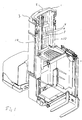
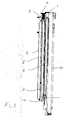
- fig 1 shows a truck equipped in accordance with the invention and fig 2a mast in accordance with the invention in a vertical section.
- the truck mast in the drawings is divided into three parts 1, 2 and 3 which are moveable relative each other.
- Each mast part includes two vertical beams at the sides of the truck and central beams 4, 5 and 6 respectively that are situated somewhat behind the others so that the base of each mast part constitutes a triangle.
- the lowest mast part 3 is fastened to the chassis of the truck and is the most outer one. Inside of this is the middle mast part 2 and the upper frame part 1.
- Cross connections 7, 8 and 9 respectively are arranged connecting the beams on the sides with the respective central beams, so that seen from above each mast part receives a slight V-shape.
- lifting pistons 10 and lifting chains for the coupled movement of the mast parts are arranged in a known manner.
- the central vertical beams are all alike and U-shaped or tube-shaped and in the central beam of the middle mast part a balance cylinder 11 is arranged with its piston rod end downward.
- the piston rod 12 rests in its bottom end against the chassis of the truck or against a suitable crossbeam in the lowest mast part 3.
- the balance cylinder 11 is advantageously attached to a reservoir for pressurized air that increase the volume of the compressed air. The pressure in the balance system is adjusted so that the pressure if possible almost lifts the upper mast parts in the bottom position. When then the mast moves upward the air expand and the balancing pressure force is reduced.
- the central vertical beams that do not contain any balance cylinder may be used for the location of hydraulic conduits as well as for electric leads.
Landscapes
- Engineering & Computer Science (AREA)
- Transportation (AREA)
- Structural Engineering (AREA)
- Civil Engineering (AREA)
- Life Sciences & Earth Sciences (AREA)
- Geology (AREA)
- Mechanical Engineering (AREA)
- Chemical & Material Sciences (AREA)
- Combustion & Propulsion (AREA)
- Forklifts And Lifting Vehicles (AREA)
Abstract
Description
- At trucks of different kinds it is well known to arrange the load forks in a telescopically extendable mast. In this way it is possible to achieve high lifting heights at the same time as the center of gravity can be kept low at transport. The telescopic mast also allow the passage of the truck through openings with far lower height than otherwise would be the case. The load forks are advantageously moveable height-wise in the uppermost mast part and at low lifts it sufficient to let the forks move in relation to this part (free lift). At higher lifts however the mast is extended. A known mast construction includes two or three more or less in each other running parts. Each part includes three vertical beams. The means are so placed that their projections on the ground constitute a isosceles triangle, which enables a construction that is strong in all directions. The mutual movements of the mast parts are coupled in known manner so that at a lifting movement all the mast parts move in relation to each other. The guides and lifting means for this are arranged close to the vertical beams that are arranged at the sides of the mast and the truck, while the third vertical part only has as its object to increase the resistance against bending of the mast lengthwise of the truck. This is not unessential since the driver with his platform at many trucks also is lifted together with the forks, as well as other means for load-handling, as fork pivot means.
- A problem at this type of mast, and in particular when also the driver and his platform etc also is lifted, is that comparatively much energy is used to lift the mast up and down, that is the effective load that is lifted is comparatively small in relation to the total load that is lifted.
- In order to remedy this problem it is in accordance with the invention suggested that between the lowest moveable mast part and the fixed mast part a balance cylinder is arranged in the moveable next to the lowest mast part in the central vertical beam alternatively in the central vertical beam of the lowest fixed mast part. In the conventional way the lifting cylinders are placed close to the beams of the mast at the sides of the truck.
- The balance cylinder makes it possible to a great extent to balance out the weight of the lifted part of the mast so that the lifting energy that at lifting movements is needed essentially corresponds to he load on the forks. By furthermore arranging the balance cylinder inside one of the front beams the balance cylinder do not in any way infringe the field of view of the operator of the truck and an aesthetically clean exterior can be retained.
- Since the moveable mast parts are coupled to each other so that they at an extending movement move relative each other the balance cylinder will even if it is only mounted between two mast parts at movement balance the weight of all the parts that are lifted. This is advantageously achieved by a chain being fastened to the lowest mast part and runs over a pulley or cogwheel on the next mast part and down to the lower end of the next mast part. The lifting hydraulic cylinders are arranged between the lowermost mast parts and when the mast part next to the lowermost one is pushed up by the lifting cylinders the chain also lifts the next mast part. If one would wish to have more mast parts than three a similar chain device can be arranged for uh additional mast part that is desired.
- By placing the balance cylinder between the upper end of the second lowest mast part and the lower end of the part of the mast fixed in the chassis of the truck the balance cylinder can thus by means of the coupling of the movement balance the entire mast weight.
- Alternatively the central vertical beams of the mast parts may be U-shaped, which simplifies the mounting of the balance cylinder. At this it is even possible to turn the beams for the lowest mast parts towards each other so that an extra large space is achieved for one or two balance cylinders.
- Since the driver accompanies the mast control orders and other signals have to be transferred to and from the drivers platform and since load handling means as for instance free lift and pivot fork means are located close to the drivers platform electric leads as well as hydraulic conduits need to be connected to the work platform, which advantageously can take place in the central beams.
- Further characteristics and advantages of the invention are apparent from the following description of an embodiment shown in the enclosed drawings. In the drawings fig 1 shows a truck equipped in accordance with the invention and fig 2a mast in accordance with the invention in a vertical section.
- The truck mast in the drawings is divided into three
parts 1, 2 and 3 which are moveable relative each other. Each mast part includes two vertical beams at the sides of the truck and central beams 4, 5 and 6 respectively that are situated somewhat behind the others so that the base of each mast part constitutes a triangle. The lowest mast part 3 is fastened to the chassis of the truck and is the most outer one. Inside of this is themiddle mast part 2 and the upper frame part 1.Cross connections 7, 8 and 9 respectively are arranged connecting the beams on the sides with the respective central beams, so that seen from above each mast part receives a slight V-shape. At the sidebeams lifting pistons 10 and lifting chains for the coupled movement of the mast parts are arranged in a known manner. The central vertical beams are all alike and U-shaped or tube-shaped and in the central beam of the middle mast part a balance cylinder 11 is arranged with its piston rod end downward. Thepiston rod 12 rests in its bottom end against the chassis of the truck or against a suitable crossbeam in the lowest mast part 3. The balance cylinder 11 is advantageously attached to a reservoir for pressurized air that increase the volume of the compressed air. The pressure in the balance system is adjusted so that the pressure if possible almost lifts the upper mast parts in the bottom position. When then the mast moves upward the air expand and the balancing pressure force is reduced. The larger the air volume that can be obtained in relation to the cross section of the balance cylinder the smaller this reduction is, but irrespective of this an essential contribution to the lifting force is obtained over the working height of the mast, which reduce the energy that has to be fed to the pump of the truck, and taken from the battery of the truck. - If so is desired the central vertical beams that do not contain any balance cylinder may be used for the location of hydraulic conduits as well as for electric leads.
- Trough the above described arrangement the sighting field of the driver despite the arranging of balance cylinder and cables will remain unchanged.
Claims (8)
- Arrangement at truck mast constituted of two or several mutually telescopically moveable parts, which each include three vertical beams located in the corners of a triangle, characterized in that between the lowest moveable mast part and the fixed mast part a balance cylinder is arranged in the moveable next to the lowest central vertical beam alternatively in the central vertical beam in the lowest fixed mast part.
- Arrangement according to claim 1, characterized in that the balance cylinder is arranged hanging, that is with the piston rod in the lower end.
- Arrangement according to claim 1 or 2, characterized in that the mast includes three mast parts.
- Device according to any of the preceding claims, characterized in that the balance cylinder is connected to a reservoir for pressurized air.
- Arrangement according to any of the preceding claims, characterized in that the movements of the mast parts are coupled together so that all the mast parts move at an elongation or contraction.
- Arrangement according to any of the preceding claims, characterized in that electrical cables and/or hydraulic conduit are arranged in the central beams of the mast.
- Arrangement according to any of the preceding claims, characterized in that the truck is a driver lifting truck where the mast lifts a drivers cage together with load handling means.
- Arrangement according to any of the preceding claims, characterized in that the load lifting means includes a free lift device and/or a swing fork means.
Applications Claiming Priority (2)
| Application Number | Priority Date | Filing Date | Title |
|---|---|---|---|
| SE0201709A SE522713C2 (en) | 2002-06-05 | 2002-06-05 | Device by truck |
| SE0201709 | 2002-06-05 |
Publications (2)
| Publication Number | Publication Date |
|---|---|
| EP1369376A1 true EP1369376A1 (en) | 2003-12-10 |
| EP1369376B1 EP1369376B1 (en) | 2017-10-11 |
Family
ID=20288083
Family Applications (1)
| Application Number | Title | Priority Date | Filing Date |
|---|---|---|---|
| EP03445070.0A Expired - Lifetime EP1369376B1 (en) | 2002-06-05 | 2003-06-02 | telescopic truck mast with balancing cylinder for the dead weight |
Country Status (3)
| Country | Link |
|---|---|
| US (1) | US7175000B2 (en) |
| EP (1) | EP1369376B1 (en) |
| SE (1) | SE522713C2 (en) |
Families Citing this family (5)
| Publication number | Priority date | Publication date | Assignee | Title |
|---|---|---|---|---|
| DE102004042336A1 (en) * | 2004-09-01 | 2006-03-02 | Jungheinrich Ag | Industrial truck with cylinder rigidly connected to load transfer device |
| US7610977B2 (en) * | 2004-09-23 | 2009-11-03 | Crown Equipment Corporation | Lift truck having hydraulically separate main frame and power unit assembly |
| US8777545B2 (en) | 2009-10-20 | 2014-07-15 | Bright Coop, Inc. | Free lift mast for truck mounted forklift |
| DE102016100695B4 (en) * | 2016-01-18 | 2025-06-26 | Jungheinrich Aktiengesellschaft | Telescopic mast for a mobile elevating work platform |
| US12600609B2 (en) | 2024-06-20 | 2026-04-14 | Mitsubishi Logisnext Americas Inc. | Hose supports for facilitating the assembly of masts for material handling vehicles and related methods |
Citations (6)
| Publication number | Priority date | Publication date | Assignee | Title |
|---|---|---|---|---|
| GB924053A (en) * | 1961-01-02 | 1963-04-18 | Coventry Climax Eng Ltd | Improvements relating to goods handling trucks |
| GB944225A (en) * | 1959-12-04 | 1963-12-11 | Linde Eismasch Ag | Improvements in or relating to load lifting devices |
| US3937346A (en) * | 1973-09-07 | 1976-02-10 | Cubic Handling Systems N.V. | Movable stacking device |
| GB2086843A (en) * | 1980-11-06 | 1982-05-19 | Jungheinrich Kg | Lifting frame for a lifting truck |
| US4709786A (en) * | 1985-02-01 | 1987-12-01 | Jungheinrich Unternehmensverwaltung Kg | Industrial truck, particularly high-lift truck, also as a high-lift truck having a displaceable mast |
| DE4306651A1 (en) * | 1993-03-03 | 1994-09-08 | Siemens Ag | Telescope column |
Family Cites Families (20)
| Publication number | Priority date | Publication date | Assignee | Title |
|---|---|---|---|---|
| US2480066A (en) * | 1947-09-25 | 1949-08-23 | Towmotor Corp | Mast construction for lift trucks |
| US2518251A (en) * | 1948-01-23 | 1950-08-08 | Yale & Towne Mfg Co | Industrial truck |
| US2666501A (en) * | 1949-12-20 | 1954-01-19 | Elwell Parker Electric Co | Hydraulically operated tier-lift mechanism for industrial trucks |
| US2678746A (en) * | 1950-11-14 | 1954-05-18 | Raymond Corp | Industrial lifting truck |
| US2821264A (en) * | 1954-12-30 | 1958-01-28 | Yale & Towne Mfg Co | Ram construction for lift truck |
| US2915144A (en) * | 1955-10-31 | 1959-12-01 | Hyster Co | Free lift truck |
| US3062325A (en) * | 1957-01-28 | 1962-11-06 | Yale & Towne Mfg Co | Lift truck load chain sheave construction |
| US2973835A (en) * | 1957-10-16 | 1961-03-07 | Yale & Towne Mfg Co | Lift truck |
| US2936047A (en) * | 1957-10-16 | 1960-05-10 | Yale & Towne Mfg Co | Lift truck |
| US2987140A (en) * | 1958-09-15 | 1961-06-06 | Hyster Co | Multiple stage mast structure |
| US3208556A (en) * | 1962-02-19 | 1965-09-28 | Towmotor Corp | Multiple stage masts for lift trucks |
| DE2741497C2 (en) * | 1977-09-15 | 1981-09-17 | Jungheinrich Unternehmensverwaltung Kg, 2000 Hamburg | Hydraulic system for the lifting drive of a lift truck |
| DE2741496A1 (en) * | 1977-09-15 | 1979-03-29 | Jungheinrich Kg | FLOOR CONVEYOR VEHICLE WITH A HYDRAULIC LIFTING CYLINDER PISTON DEVICE FOR A LIFTING FRAME |
| JPS5548598A (en) * | 1978-09-29 | 1980-04-07 | Fujitsu Fanuc Ltd | Load reducing device of industrial robot |
| US4552250A (en) * | 1983-04-22 | 1985-11-12 | Crown Controls Corporation | Lift truck |
| AU553161B2 (en) * | 1984-03-09 | 1986-07-03 | Cincinnati Milacron Inc. | Manipulator with counter balance |
| SE455498B (en) * | 1986-04-28 | 1988-07-18 | Bt Ind Ab | HYDRAULIC LIFTING DEVICE FOR LIFTING UNIT |
| US4721187A (en) * | 1987-03-23 | 1988-01-26 | The Raymond Corporation | Lift truck mast structure |
| SE461391B (en) * | 1987-10-28 | 1990-02-12 | Bt Ind Ab | HYDRAULIC LIFTING DEVICE |
| US4896748A (en) * | 1988-05-27 | 1990-01-30 | Caterpillar Industrial Inc. | Full free lift mast assembly |
-
2002
- 2002-06-05 SE SE0201709A patent/SE522713C2/en not_active IP Right Cessation
-
2003
- 2003-06-02 EP EP03445070.0A patent/EP1369376B1/en not_active Expired - Lifetime
- 2003-06-03 US US10/453,025 patent/US7175000B2/en not_active Expired - Lifetime
Patent Citations (6)
| Publication number | Priority date | Publication date | Assignee | Title |
|---|---|---|---|---|
| GB944225A (en) * | 1959-12-04 | 1963-12-11 | Linde Eismasch Ag | Improvements in or relating to load lifting devices |
| GB924053A (en) * | 1961-01-02 | 1963-04-18 | Coventry Climax Eng Ltd | Improvements relating to goods handling trucks |
| US3937346A (en) * | 1973-09-07 | 1976-02-10 | Cubic Handling Systems N.V. | Movable stacking device |
| GB2086843A (en) * | 1980-11-06 | 1982-05-19 | Jungheinrich Kg | Lifting frame for a lifting truck |
| US4709786A (en) * | 1985-02-01 | 1987-12-01 | Jungheinrich Unternehmensverwaltung Kg | Industrial truck, particularly high-lift truck, also as a high-lift truck having a displaceable mast |
| DE4306651A1 (en) * | 1993-03-03 | 1994-09-08 | Siemens Ag | Telescope column |
Also Published As
| Publication number | Publication date |
|---|---|
| US7175000B2 (en) | 2007-02-13 |
| SE0201709L (en) | 2003-12-06 |
| SE0201709D0 (en) | 2002-06-05 |
| US20030230456A1 (en) | 2003-12-18 |
| EP1369376B1 (en) | 2017-10-11 |
| SE522713C2 (en) | 2004-03-02 |
Similar Documents
| Publication | Publication Date | Title |
|---|---|---|
| US10023448B2 (en) | Lift truck with mast | |
| EP2354077B1 (en) | Mobile crane having counterweight | |
| EP0244060B1 (en) | Mast construction for pedestal scaffold | |
| KR102766040B1 (en) | Order picker materials handling vehicle with improved downward visibility when driving elevated | |
| NL2004999C2 (en) | Load-handling apparatus adapted to be mounted on an elevatable lift carriage of a lift truck as well as a lift truck comprising such a load-handling apparatus. | |
| US2399632A (en) | Industrial truck | |
| SA515360152B1 (en) | Device for lifting objects | |
| US3172500A (en) | Load-lifting trucks | |
| EP2825497B1 (en) | Order pickers | |
| US6116577A (en) | Service lift with curved mast | |
| US20030230456A1 (en) | Control method and device at truck | |
| KR101507626B1 (en) | Camera fixing device of forklift for safety | |
| US3727781A (en) | Lift truck load lifting mechanism | |
| EP3532424A1 (en) | Foldable crane | |
| US7134527B2 (en) | Forklift upright assembly | |
| CN220519999U (en) | Working arm and underground crane truck with same | |
| CN208949739U (en) | Lifting work platforms for lanyards | |
| GB2250267A (en) | Improvements in or relating to fork lift trucks | |
| NL1030868C2 (en) | Device and method for lifting loads. | |
| EP0286300A1 (en) | Personnel access lift boom | |
| CN208029491U (en) | Cotton picker air hose control mechanism | |
| EP2295366A1 (en) | Forklift mast | |
| CN211078277U (en) | Building material lifting device | |
| CN111003667A (en) | Crawler type elevator and pushing method thereof | |
| CN213322814U (en) | Get and put article and use lift platform and vehicle |
Legal Events
| Date | Code | Title | Description |
|---|---|---|---|
| PUAI | Public reference made under article 153(3) epc to a published international application that has entered the european phase |
Free format text: ORIGINAL CODE: 0009012 |
|
| AK | Designated contracting states |
Kind code of ref document: A1 Designated state(s): AT BE BG CH CY CZ DE DK EE ES FI FR GB GR HU IE IT LI LU MC NL PT RO SE SI SK TR |
|
| AX | Request for extension of the european patent |
Extension state: AL LT LV MK |
|
| 17P | Request for examination filed |
Effective date: 20040611 |
|
| AKX | Designation fees paid |
Designated state(s): AT BE BG CH CY CZ DE DK EE ES FI FR GB GR HU IE IT LI LU MC NL PT RO SE SI SK TR |
|
| 17Q | First examination report despatched |
Effective date: 20060918 |
|
| STAA | Information on the status of an ep patent application or granted ep patent |
Free format text: STATUS: EXAMINATION IS IN PROGRESS |
|
| GRAP | Despatch of communication of intention to grant a patent |
Free format text: ORIGINAL CODE: EPIDOSNIGR1 |
|
| STAA | Information on the status of an ep patent application or granted ep patent |
Free format text: STATUS: GRANT OF PATENT IS INTENDED |
|
| INTG | Intention to grant announced |
Effective date: 20170523 |
|
| GRAS | Grant fee paid |
Free format text: ORIGINAL CODE: EPIDOSNIGR3 |
|
| GRAA | (expected) grant |
Free format text: ORIGINAL CODE: 0009210 |
|
| STAA | Information on the status of an ep patent application or granted ep patent |
Free format text: STATUS: THE PATENT HAS BEEN GRANTED |
|
| AK | Designated contracting states |
Kind code of ref document: B1 Designated state(s): AT BE BG CH CY CZ DE DK EE ES FI FR GB GR HU IE IT LI LU MC NL PT RO SE SI SK TR |
|
| RAP1 | Party data changed (applicant data changed or rights of an application transferred) |
Owner name: TOYOTA MATERIAL HANDLING EUROPE AB |
|
| REG | Reference to a national code |
Ref country code: GB Ref legal event code: FG4D |
|
| REG | Reference to a national code |
Ref country code: CH Ref legal event code: EP |
|
| REG | Reference to a national code |
Ref country code: IE Ref legal event code: FG4D |
|
| REG | Reference to a national code |
Ref country code: AT Ref legal event code: REF Ref document number: 935826 Country of ref document: AT Kind code of ref document: T Effective date: 20171115 |
|
| REG | Reference to a national code |
Ref country code: DE Ref legal event code: R096 Ref document number: 60350680 Country of ref document: DE |
|
| REG | Reference to a national code |
Ref country code: NL Ref legal event code: MP Effective date: 20171011 |
|
| REG | Reference to a national code |
Ref country code: AT Ref legal event code: MK05 Ref document number: 935826 Country of ref document: AT Kind code of ref document: T Effective date: 20171011 |
|
| PG25 | Lapsed in a contracting state [announced via postgrant information from national office to epo] |
Ref country code: NL Free format text: LAPSE BECAUSE OF FAILURE TO SUBMIT A TRANSLATION OF THE DESCRIPTION OR TO PAY THE FEE WITHIN THE PRESCRIBED TIME-LIMIT Effective date: 20171011 |
|
| PG25 | Lapsed in a contracting state [announced via postgrant information from national office to epo] |
Ref country code: SE Free format text: LAPSE BECAUSE OF FAILURE TO SUBMIT A TRANSLATION OF THE DESCRIPTION OR TO PAY THE FEE WITHIN THE PRESCRIBED TIME-LIMIT Effective date: 20171011 Ref country code: FI Free format text: LAPSE BECAUSE OF FAILURE TO SUBMIT A TRANSLATION OF THE DESCRIPTION OR TO PAY THE FEE WITHIN THE PRESCRIBED TIME-LIMIT Effective date: 20171011 Ref country code: ES Free format text: LAPSE BECAUSE OF FAILURE TO SUBMIT A TRANSLATION OF THE DESCRIPTION OR TO PAY THE FEE WITHIN THE PRESCRIBED TIME-LIMIT Effective date: 20171011 |
|
| PG25 | Lapsed in a contracting state [announced via postgrant information from national office to epo] |
Ref country code: AT Free format text: LAPSE BECAUSE OF FAILURE TO SUBMIT A TRANSLATION OF THE DESCRIPTION OR TO PAY THE FEE WITHIN THE PRESCRIBED TIME-LIMIT Effective date: 20171011 Ref country code: GR Free format text: LAPSE BECAUSE OF FAILURE TO SUBMIT A TRANSLATION OF THE DESCRIPTION OR TO PAY THE FEE WITHIN THE PRESCRIBED TIME-LIMIT Effective date: 20180112 Ref country code: BG Free format text: LAPSE BECAUSE OF FAILURE TO SUBMIT A TRANSLATION OF THE DESCRIPTION OR TO PAY THE FEE WITHIN THE PRESCRIBED TIME-LIMIT Effective date: 20180111 |
|
| REG | Reference to a national code |
Ref country code: DE Ref legal event code: R097 Ref document number: 60350680 Country of ref document: DE |
|
| PG25 | Lapsed in a contracting state [announced via postgrant information from national office to epo] |
Ref country code: EE Free format text: LAPSE BECAUSE OF FAILURE TO SUBMIT A TRANSLATION OF THE DESCRIPTION OR TO PAY THE FEE WITHIN THE PRESCRIBED TIME-LIMIT Effective date: 20171011 Ref country code: SK Free format text: LAPSE BECAUSE OF FAILURE TO SUBMIT A TRANSLATION OF THE DESCRIPTION OR TO PAY THE FEE WITHIN THE PRESCRIBED TIME-LIMIT Effective date: 20171011 Ref country code: CZ Free format text: LAPSE BECAUSE OF FAILURE TO SUBMIT A TRANSLATION OF THE DESCRIPTION OR TO PAY THE FEE WITHIN THE PRESCRIBED TIME-LIMIT Effective date: 20171011 Ref country code: DK Free format text: LAPSE BECAUSE OF FAILURE TO SUBMIT A TRANSLATION OF THE DESCRIPTION OR TO PAY THE FEE WITHIN THE PRESCRIBED TIME-LIMIT Effective date: 20171011 |
|
| REG | Reference to a national code |
Ref country code: FR Ref legal event code: PLFP Year of fee payment: 16 |
|
| PLBE | No opposition filed within time limit |
Free format text: ORIGINAL CODE: 0009261 |
|
| STAA | Information on the status of an ep patent application or granted ep patent |
Free format text: STATUS: NO OPPOSITION FILED WITHIN TIME LIMIT |
|
| PG25 | Lapsed in a contracting state [announced via postgrant information from national office to epo] |
Ref country code: RO Free format text: LAPSE BECAUSE OF FAILURE TO SUBMIT A TRANSLATION OF THE DESCRIPTION OR TO PAY THE FEE WITHIN THE PRESCRIBED TIME-LIMIT Effective date: 20171011 Ref country code: IT Free format text: LAPSE BECAUSE OF FAILURE TO SUBMIT A TRANSLATION OF THE DESCRIPTION OR TO PAY THE FEE WITHIN THE PRESCRIBED TIME-LIMIT Effective date: 20171011 |
|
| 26N | No opposition filed |
Effective date: 20180712 |
|
| PG25 | Lapsed in a contracting state [announced via postgrant information from national office to epo] |
Ref country code: SI Free format text: LAPSE BECAUSE OF FAILURE TO SUBMIT A TRANSLATION OF THE DESCRIPTION OR TO PAY THE FEE WITHIN THE PRESCRIBED TIME-LIMIT Effective date: 20171011 |
|
| REG | Reference to a national code |
Ref country code: CH Ref legal event code: PL |
|
| REG | Reference to a national code |
Ref country code: BE Ref legal event code: MM Effective date: 20180630 |
|
| REG | Reference to a national code |
Ref country code: IE Ref legal event code: MM4A |
|
| PG25 | Lapsed in a contracting state [announced via postgrant information from national office to epo] |
Ref country code: MC Free format text: LAPSE BECAUSE OF FAILURE TO SUBMIT A TRANSLATION OF THE DESCRIPTION OR TO PAY THE FEE WITHIN THE PRESCRIBED TIME-LIMIT Effective date: 20171011 Ref country code: LU Free format text: LAPSE BECAUSE OF NON-PAYMENT OF DUE FEES Effective date: 20180602 |
|
| PG25 | Lapsed in a contracting state [announced via postgrant information from national office to epo] |
Ref country code: IE Free format text: LAPSE BECAUSE OF NON-PAYMENT OF DUE FEES Effective date: 20180602 Ref country code: CH Free format text: LAPSE BECAUSE OF NON-PAYMENT OF DUE FEES Effective date: 20180630 Ref country code: LI Free format text: LAPSE BECAUSE OF NON-PAYMENT OF DUE FEES Effective date: 20180630 |
|
| PG25 | Lapsed in a contracting state [announced via postgrant information from national office to epo] |
Ref country code: BE Free format text: LAPSE BECAUSE OF NON-PAYMENT OF DUE FEES Effective date: 20180630 |
|
| PG25 | Lapsed in a contracting state [announced via postgrant information from national office to epo] |
Ref country code: TR Free format text: LAPSE BECAUSE OF FAILURE TO SUBMIT A TRANSLATION OF THE DESCRIPTION OR TO PAY THE FEE WITHIN THE PRESCRIBED TIME-LIMIT Effective date: 20171011 |
|
| PG25 | Lapsed in a contracting state [announced via postgrant information from national office to epo] |
Ref country code: HU Free format text: LAPSE BECAUSE OF FAILURE TO SUBMIT A TRANSLATION OF THE DESCRIPTION OR TO PAY THE FEE WITHIN THE PRESCRIBED TIME-LIMIT; INVALID AB INITIO Effective date: 20030602 Ref country code: PT Free format text: LAPSE BECAUSE OF FAILURE TO SUBMIT A TRANSLATION OF THE DESCRIPTION OR TO PAY THE FEE WITHIN THE PRESCRIBED TIME-LIMIT Effective date: 20171011 |
|
| PG25 | Lapsed in a contracting state [announced via postgrant information from national office to epo] |
Ref country code: CY Free format text: LAPSE BECAUSE OF FAILURE TO SUBMIT A TRANSLATION OF THE DESCRIPTION OR TO PAY THE FEE WITHIN THE PRESCRIBED TIME-LIMIT Effective date: 20171011 |
|
| PGFP | Annual fee paid to national office [announced via postgrant information from national office to epo] |
Ref country code: GB Payment date: 20220621 Year of fee payment: 20 |
|
| PGFP | Annual fee paid to national office [announced via postgrant information from national office to epo] |
Ref country code: FR Payment date: 20220624 Year of fee payment: 20 |
|
| PGFP | Annual fee paid to national office [announced via postgrant information from national office to epo] |
Ref country code: DE Payment date: 20220628 Year of fee payment: 20 |
|
| REG | Reference to a national code |
Ref country code: DE Ref legal event code: R071 Ref document number: 60350680 Country of ref document: DE |
|
| REG | Reference to a national code |
Ref country code: GB Ref legal event code: PE20 Expiry date: 20230601 |
|
| PG25 | Lapsed in a contracting state [announced via postgrant information from national office to epo] |
Ref country code: GB Free format text: LAPSE BECAUSE OF EXPIRATION OF PROTECTION Effective date: 20230601 |