EP2295366A1 - Forklift mast - Google Patents
Forklift mast Download PDFInfo
- Publication number
- EP2295366A1 EP2295366A1 EP10176891A EP10176891A EP2295366A1 EP 2295366 A1 EP2295366 A1 EP 2295366A1 EP 10176891 A EP10176891 A EP 10176891A EP 10176891 A EP10176891 A EP 10176891A EP 2295366 A1 EP2295366 A1 EP 2295366A1
- Authority
- EP
- European Patent Office
- Prior art keywords
- mast
- pair
- profiles
- profile elements
- forklift truck
- Prior art date
- Legal status (The legal status is an assumption and is not a legal conclusion. Google has not performed a legal analysis and makes no representation as to the accuracy of the status listed.)
- Granted
Links
Images
Classifications
-
- B—PERFORMING OPERATIONS; TRANSPORTING
- B66—HOISTING; LIFTING; HAULING
- B66F—HOISTING, LIFTING, HAULING OR PUSHING, NOT OTHERWISE PROVIDED FOR, e.g. DEVICES WHICH APPLY A LIFTING OR PUSHING FORCE DIRECTLY TO THE SURFACE OF A LOAD
- B66F9/00—Devices for lifting or lowering bulky or heavy goods for loading or unloading purposes
- B66F9/06—Devices for lifting or lowering bulky or heavy goods for loading or unloading purposes movable, with their loads, on wheels or the like, e.g. fork-lift trucks
- B66F9/075—Constructional features or details
- B66F9/08—Masts; Guides; Chains
Definitions
- the mast profiles When all parts have been lowered and the mast is therefore in its lowest position, all parts of the mast profiles will be lined up at the top, whereas at the base, the inner profile(s) extends between the tyres and wheels, and the outer one not.
- the outer mast profiles are partially or entirely positioned above the wheels or tyres to create a wider opening to the inner mast section.
- the increased mast opening offers a significantly better view of the forks compared to the conventional forklift mast with comparable clearance height.
- a comparable lifting height can easily be re-established by adding additional shorter mast parts outwardly of the inner mast part.
- the telescopic mast further includes a fork carriage, adapted to carry at least one single fork, clamp, or other attachment for carrying a load.
- This fork carriage can be attached to the inner mast part, when the outer mast part's lower end is adapted to be attached to a vehicle, such as a forklift truck, preferably with the option of being tilted with respect thereto.
- the fork carriage can also be attached to the outer mast part, when only the inner mast part and not the outer mast part's lower end is adapted to be attached to a forklift truck.
- a general benefit of telescopic masts for forklift trucks is that an increased lifting height does not need to result in an increased height of the forklift truck. There is some freedom in design as to whether the innermost mast part or the outermost mast part is attached to the truck. As a consequence the fork carriage will then be carried by the other of the inner and outermost mast part.
- the invention thus relates to a new specific construction of the outer mast part i.e. the outer mast parts for forklift trucks, reach trucks, stackers and otherwise of machines which move pallets and/or goods in a vertical manner, with a particular purpose of creating a better view through the mast of the goods to be moved or lifted.
- the outer mast part i.e. the outer mast parts of a triple mast
- the outer mast part are positioned partially or entirely above the tyres which causes the mast profiles to be a bit wider apart, thus resulting in a wider opening in the inner mast part.
- the wider opening provides a significant improvement in visibility of the forks and the load to be lifted. Therefore, an important aspect of this invention is positioning the outer mast profiles entirely or partially above the tyres or the conveying means of the forklift truck.
Abstract
Description
- This invention relates to a mast for forklift trucks, and similar machines. More specifically this invention relates to a telescopic mast with an increased visibility range, through the middle of the mast.
- A number of proposals to improve the forward visibility through a mast have been published in the Japanese utility models
JP 59-123.096 JP 62-132.099 US 7096999 ,US 6505710 andUS 5000293 . In these known constructions certain parts of the lifting mechanism have been positioned in such a way that the obstruction in the visibility range is minimised. Nevertheless, the view remains obstructed by individual parts of the telescopic mast. Conventionally masts are customary positioned in between the wheels or other transport of the forklift truck and extend straight up from there, not considering welded on parts. In this case, the mast profiles are all more or less the same length and the positioning of the outer mast parts will determine the position of the inner mast parts. - Accordingly it is one of the present invention's objects to meet the general need of the operators of the forklift trucks to have a better view in surveying the forks of their trucks as well as the cargo which is to be lifted or transported. This view would normally be obstructed as the operators are seated behind the mast and these have to look through a free space between vertical members of the mast to see what is happening in front by the tips of the forks. More specifically it is the object to improve the operator's view in a forward direction from the driver's seat through the opening in between the vertical mast members of the cargo to be lifted and transported in such a way that the operator can operate with more confidence and greater speed yet decrease any damage to cargo and pallets. In a more general sense it is thus an object of the invention to overcome or ameliorate at least one of the disadvantages of the prior art. It is also an object of the present invention to provide alternative structures which are less cumbersome in operation and which moreover can be made relatively inexpensively. A particular object of the invention is to provide an alternative mast structure that allows the mast to be positioned partially above the wheels of a forklift truck. Alternatively it is also an object of the invention to at least provide the public with a useful choice.
- To this end the invention provides a telescopic mast for a vehicle such as a forklift truck including at least an outer mast part and an inner mast part, which outer and inner mast parts are slidable with respect to each other, wherein the outer and inner mast parts are each provided respectively with an outer pair and an inner pair of left and right profile elements, wherein the inner pair of left and right profile elements of the inner mast part are mounted in between the outer pair of left and right profile elements of the outer mast part, and wherein the left and right profile elements of the outer pair are shorter in length than the left and right profile elements of the inner pair.
- The operator's visibility range is increased with the mast according to this invention, by placing the guiding profiles, also called mast profiles, more outwardly. The outer mast profile is therefore positioned above the tyres of the forklift truck. By placing this mast profile above the wheels, tyres, or any other transport means or conveying means such as caterpillar tracks, this profile will be shorter than the inner mast profile(s), so that the fork carriage will be able to be lowered right down to the ground. Thus the characteristics of this invention are that the outer mast profile(s) is situated above the tyres or wheels and the fact that there is a difference in length between the different mast profiles. When all parts have been lowered and the mast is therefore in its lowest position, all parts of the mast profiles will be lined up at the top, whereas at the base, the inner profile(s) extends between the tyres and wheels, and the outer one not. In a solution according to the invention, the outer mast profiles are partially or entirely positioned above the wheels or tyres to create a wider opening to the inner mast section. The increased mast opening offers a significantly better view of the forks compared to the conventional forklift mast with comparable clearance height. A comparable lifting height can easily be re-established by adding additional shorter mast parts outwardly of the inner mast part.
- The telescopic mast according to the invention can also optionally be provided with an additional middle mast part with a middle pair of left and right profile elements, arranged to be slidable in a position with the left and right profile elements of the outer pair outwardly and with the left and right profile element of the inner pair inwardly of the left and right profile elements of the middle pair of the middle mast part. In such an arrangement it is preferred when the left and right profile elements of the middle pair are shorter than the left and right profile elements of the inner pair. By also keeping the additional middle mast part shorter, the middle mast profiles may also be positioned above the front wheels of a forklift truck.
- It can also be advantageous when the telescopic mast further includes a fork carriage, adapted to carry at least one single fork, clamp, or other attachment for carrying a load. This fork carriage can be attached to the inner mast part, when the outer mast part's lower end is adapted to be attached to a vehicle, such as a forklift truck, preferably with the option of being tilted with respect thereto. Alternatively the fork carriage can also be attached to the outer mast part, when only the inner mast part and not the outer mast part's lower end is adapted to be attached to a forklift truck. A general benefit of telescopic masts for forklift trucks is that an increased lifting height does not need to result in an increased height of the forklift truck. There is some freedom in design as to whether the innermost mast part or the outermost mast part is attached to the truck. As a consequence the fork carriage will then be carried by the other of the inner and outermost mast part.
- In a further embodiment of the invention the telescopic mast preferably has the individual pairs of left and right mast profiles arranged to be unequal in length, with respect to each other, and with a front view of the assembled mast being wider at its top and narrower at its bottom and being inherently funnel shaped.
- The invention thus relates to a new specific construction of the outer mast part i.e. the outer mast parts for forklift trucks, reach trucks, stackers and otherwise of machines which move pallets and/or goods in a vertical manner, with a particular purpose of creating a better view through the mast of the goods to be moved or lifted. With this new construction, according to the invention, the outer mast part i.e. the outer mast parts of a triple mast, are positioned partially or entirely above the tyres which causes the mast profiles to be a bit wider apart, thus resulting in a wider opening in the inner mast part. In comparison with the conventional constructions, the wider opening provides a significant improvement in visibility of the forks and the load to be lifted. Therefore, an important aspect of this invention is positioning the outer mast profiles entirely or partially above the tyres or the conveying means of the forklift truck.
- The invention also provides a combination of a forklift truck and a telescopic mast having the technical features of the invention. For such a combination it is further advantageous when the pair of inner mast profiles is positioned in between front wheels while the outer pair of left and right mast profiles is positioned above the wheels, wherein the individual pairs of left and right mast profiles are unequal in length and wherein a frontal view of the assembled mast is inherently funnel shaped, being wider at its top and narrower at its bottom. In such a combination it is also preferred when the left and right mast profile of each outer mast part's lower end join the lower narrowest part of the funnel construction, the lower narrowest part of the outer mast profile, which has no guiding function, thereby serves to mount the mast to the forklift truck and pivotably connects to a titling point at a front axle of the forklift truck.
- The combination according to the invention may also advantageously have the outer left and right mast profiles, positioned either entirely or partially above the wheels or like conveying means of the forklift truck. In such a preferred combination the lower narrow part of the outer mast part can advantageously be mounted towards the back, diagonally above the axle. In such an arrangement, or alternatively, the titling point of the mast may be positioned higher than the lower narrow part of the outer mast part.
- The combination according to the invention may also preferably be equipped with a triple or multiple part mast and have the middle pair of mast profiles substantially the same length as the outer mast part, but shorter than the mast profiles of the inner mast part, so that the middle pair of mast profiles, similar to the outer pair of mast profiles, can be positioned above the wheels.
- There is a lot to be gained with regard to the visibility through the masts in the triple or multiple masts by placing the middle mast profiles, just like the outer mast profiles, above the wheels or tyres and therefore not extending it towards the bottom, in between the wheels. The length of the middle mast profile(s) is thereby virtually the same as that of the mast profile of the outer mast part and thus shorter than the mast profile of the inner mast part. This particular type is not in particular described or illustrated in the accompanying drawing, but will be easily conceived by a skilled person. In this particular case an important aspect of the view of the inherent funnel shaped outer mast part remains, the funnel shape however, becomes wider at the top.
- The above and further objects, features and advantages of the invention will be clarified in more detail by the below description of preferred embodiments in conjunction with the accompanying drawings, in which:
-
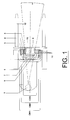
Figure 1 shows a schematic top view of a conventional forklift truck with a triple telescopic mast; -
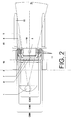
Figure 2 shows a schematic top view of a forklift truck fitted with a telescopic mast according to the invention; -
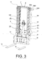
Figure 3 shows a perspective view of the assembled telescopic mast according to the invention; -
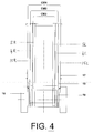
Figure 4 is a schematic frontal view of the telescopic mast according to the invention as fitted to a forklift truck, in which the forks and the fork carriage have been omitted for clarity; and -
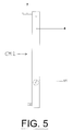
Figure 5 is a side view of a middle mast part. -
Figure 1 is a schematic top view of a conventional triple mast, in which the limited visibility of anoperator 1 has been indicated by sight lines 2. The sight lines 2 represent the visibility range of a conventional forklift mast (not considering a possible additional obstruction by presence of any lift cylinders). A forklift mast includes of several mast guiding parts, these are calledmast profiles top bridge 6 connects the outer pair ofmast profiles 3 of an outer mast part CM1. A middle upper connectingbridge 7 connects the middle pair ofmast profiles 4 of a middle mast part CM2. An inner upper connectingbridge 8 connects the inner pair ofmast profiles 5 of an inner mast part CM3. Together these form the mast parts CM1, CM2 and CM3, respectively. A complete mast always includes a minimum of two mast parts CM1 and CM2, which slide in and out of each other in order to lift the cargo. Triple-and four part masts are available to lift to higher heights. A triple mast is the most common one and will be described as an example in relation to the accompanying drawings. The invention, however, can also be applied to any other mast type. The various mast parts CM1, CM2 and CM3 slide up and down in each other, driven by two hydraulic lift cylinders or cables (not illustrated but known to the skilled person) which have been positioned to the left and right behind the mast parts CM1, CM2 and CM3. Inside the mast part CM3 afree lift cylinder 9 may be placed for free lifting. This means that afork carriage 10 will be lifted without the mast parts CM2 and/or CM3 sliding up.Mast rollers 11, such as wheels with steel bearings, are used to enable mast parts CM1, CM2 and CM3, which contribute to the guiding inside theu-shaped mast profile - The outer mast part CM1 is mounted to the machine and the inner mast part CM3 carries the
fork carriage 10 on whichforks 12 are mounted. By a triple mast, a middle mast part CM2 can be placed in between the inner and outer mast part. - Characteristic of these conventional masts, as indicated in
Figure 1 , is that allmast profiles different mast profiles -
Figure 2 in a schematic top view shows a triple mast, according to the invention, in which the wider visibility range of theoperator 1 is indicated bysight lines 14. Here it is clearly visible that a pair of outer mast profiles 15 of an outer mast part CM4, are each positioned above the wheels or tyres, such as thefront wheels 16 of the forklift truck. The outerupper connecting bridge 6 interconnects the individual left and right mast guiding profiles (15L and 15R inFigure 3 ) of the outer mast part CM4. -
Figure 3 is a perspective illustration of a complete three part telescopic mast according to the invention, in which the fork carriage and the fork is partially deleted where it meets with the outer mast part, to better show the shape of the outer mast part at its bottom. In this portion ofFigure 3 it can be seen that the outer mast part CM4 has been narrowed at its bottom, a pair of mast profiles 15 of this outer mast part ends just beneath the mounting 17 for a tilt cylinder. The tilt cylinder mounting 17 is a welded on part for fixation of tilt cylinders (not shown, but conventional). Each right hand and lefthand guiding profile second plates mast profile 15 in such a way that the narrowed supporting frame is situated in between the wheels or tyres of the forklift truck and the mast profiles 15 being arranged on top thereof. The first and second supporting frame plates connect the pair of outermast guiding profiles 15 to a mast tilting point, for tilting about a front axle of a forklift truck. The mast thereby takes a funnel-like shaped as a result of being wider at its top and narrower at its bottom. Thebottom mast rollers 11 have been placed on the mast part which is placed inside CM2, in such a way that these, with a descended mast, stay just above the narrow part of the outer mast CM4 thus resulting in a difference in length of the mast profile (guiding parts) of the outer mast part CM4 and the inner and outer mast parts CM2, CM3 which are situated inwardly thereof. A significant aspect of this mast according to the invention, is that theinner mast profiles 4 and/or 5 are situated in between the tyres whilst theouter mast profile 15 has been placed above the tyres, that the length of thedifferent mast profiles mast profiles -
Figure 4 is a frontal view of an entire mast mounted to a forklift truck, but with the forks and the fork carriage deleted for clarity. The funnel shape is clearly recognisable as well as the fact that the right hand and lefthand mast profiles wheels 16 and that theguiding mast profiles guiding mast profiles mast part CM 4 and that theguiding mast profiles 4 of this mast part CM2 is the first guiding part which is situated in between and adjacent to thewheels 16. - In the frontal view the inherent funnel shaped construction of the mast can be clearly seen in which the outer mast part is narrower at the bottom in between the tyres or wheels and wider at the top above the wheels. The mast profile of the outer mast part CM4 is situated above the funnel construction, the lower narrower part which has no guiding function, is for mounting the mast to the forklift machine at the titling point of its the axle. This part can also be constructed differently, for example by arranging it toward the back (slanted) above the axle, or in the event that the tilting point of the mast would be higher.
-
Figure 5 is a side view of the second mast part CM2. The pair ofmast profiles 4 of this mast part CM2 are situated nearest to the wheels (16 inFigure 4 ). Shown clearly inFigure 5 is that thebottom mast roller 11 has been placed at a higher level to engage with the shorter outer mast part profiles (15 inFigure 4 ), which is positioned higher above the wheels (16 inFigure 4 ). Part of thismast profile 4, which in some types could replacemast profiles 5, extends below themast roller 11 and between thewheels 16. This is the moving part at the outer most side against thewheels 16. This bottom part of the guidingprofile 4 mainly serves the purpose of an internal guiding profile for the fork carriage. - Thus the invention provides a widened forklift mast with better visibility and relates to an improved construction of the outer mast parts for forklift trucks offering an increased visibility range in or through the mast compared to the conventional constructions. The outer mast profiles are partially or entirely positioned above the wheels or tyres to create a wider opening at the inner mast section. The increased mast opening offers a significantly better view of the forks compared to the conventional forklift mast with comparable lifting and clearance height. In a frontal view the funnel shape is visible. Extra visibility can be obtained by placing the middle mast parts of a three part mast above the front wheels as well. Conventional masts, have up until now, been placed in between the front wheels and go straight up from there, not taking into account the welded on parts.
- Accordingly there is disclosed in the above a telescopic mast for a vehicle such as a forklift truck that includes at least an outer mast part (CM4) and an inner mast part (CM3). The outer and inner mast parts are slidable with respect to each other and the outer and inner mast parts (CM4, CM3) are each provided respectively with an outer pair (15) and an inner pair (5) of left and right profile elements (15L, 15R; 5L, 5R). The inner pair (5) of left and right profile elements (5L, 5R) of the inner mast part (CM3) are mounted in between the outer pair (15) of left and right profile elements (15L, 15R) of the outer mast part (CM4). The left and right profile elements (15L, 15R) of the outer pair (15) are shorter in length than the left and right profile elements of the inner pair (5).
- It is thus believed that the operation and construction of the present invention will be apparent from the foregoing description. The invention is not limited to any embodiment herein described and, within the purview of the skilled person; modifications are possible which should be considered within the scope of the appended claims. Equally all kinematic inversions are considered inherently disclosed and to be within the scope of the present invention. In the claims, any reference signs shall not be construed as limiting the claim. The term 'comprising' when used in this description or the appended claims should not be construed in an exclusive or exhaustive sense but rather in an inclusive sense. Thus the expression 'comprising' as used herein does not exclude the presence of other elements or steps in addition to those listed in a claim. Furthermore, the words 'a' and 'an' shall not be construed as limited to 'only one', but instead are used to mean 'at least one', and do not exclude a plurality. The mere fact that certain measures are recited in mutually different claims does not indicate that a combination of these measures cannot be used to advantage. Expressions such as: "means for ..." should be read as: "component configured for ..." or "member constructed to ..." and should be construed to include equivalents for the structures disclosed. The use of expressions like: "critical", "preferred", "especially preferred" etc. is not intended to limit the invention. Features which are not specifically or explicitly described or claimed may be additionally included in the structure according to the present invention without deviating from its scope.
-
- 1 operator;
- 2 conventional view sight lines;
- 3 pair of outer mast guiding profiles;
- 4 pair of middle mast guiding profiles (the middle left and right mast profiles are also referred to as 4L and 4R, see
Figure 3 ); - 5 pair of inner mast guiding profiles (the inner left and right mast profiles are also referred to as 5L and 5R, see
Figure 3 ); - 6 upper connecting bridge, which connects both mast profiles (3) of the outer mast part (CM1 and/or CM 4);
- 7 upper connecting bridge, which connects both mast profiles (4) of the middle mast part (CM2);
- 8 upper connecting bridge, which connects both mast profiles (5) of the inner mast part (CM3);
- 9 hydraulic free lift cylinder;
- 10 fork carriage;
- 11 mast roller;
- 12 fork;
- 14 improved view sight lines;
- 15 pair of outer mast guiding profiles of an improved forklift mast (the outer left and right mast profiles are also referred to as 15L and 15R, see
Figure 3 ); - 16 wheel and/or tyre;
- 17 tilt cylinder mounting;
- 18 first supporting frame plate for connecting the outer mast guiding profiles (15) to a mast tilting point for tilting about a front axle;
- 19 second supporting frame plate for connecting the outer mast guiding profiles (15) to a mast tilting point for tilting about a front axle;
- CM1 outer mast part of a conventional mast (assembled mast profiles with mast rollers and welded on parts); CM1 is an
assembly including items - CM2 middle mast part (assembled mast profiles with mast rollers); CM2 is an
assembly including items - CM3 inners mast part (assembled mast profiles with mast rollers); CM3 is an
assembly including items - CM4 Outer mast part of the improved mast according to the invention (assembled mast profiles with mast rollers and welded on parts); CM4 is an
assembly including items
Claims (14)
- Telescopic mast for a vehicle such as a forklift truck including at least an outer mast part and an inner mast part, which outer and inner mast parts are slidable with respect to each other, wherein the outer and inner mast parts are each provided respectively with an outer pair and an inner pair of left and right profile elements, wherein the inner pair of left and right profile elements of the inner mast part are mounted in between the outer pair of left and right profile elements of the outer mast part, and wherein the left and right profile elements of the outer pair are shorter in length than the left and right profile elements of the inner pair.
- Telescopic mast according to claim 1, wherein a middle mast part with a middle pair of left and right profile elements, is arranged to be slidable in a position with the left and right profile elements of the outer pair outwardly and with the left and right profile element of the inner pair inwardly of the left and right profile elements of the middle pair of the middle mast part.
- Telescopic mast according to claim 2, wherein the left and right profile elements of the middle pair are shorter than the left and right profile elements of the inner pair.
- Telescopic mast according to claim 1, 2, or 3, further including a fork carriage, adapted to carry at least one single fork or attachment for carrying a load.
- Telescopic mast according to one of claims 1-4, wherein the outer mast part's lower end is adapted to be attached to a vehicle, such as a forklift truck, preferably with the option of being tilted with respect thereto.
- Telescopic mast according to one of claims 1-4, wherein only the inner mast part and not the outer mast part's lower end is adapted to be attached to a vehicle, such as a forklift truck.
- Telescopic mast according to one of claims 1-6, wherein the individual pairs of left and right mast profiles are unequal in length, with respect to each other, and wherein a front view of the assembled mast is wider at its top and narrower at its bottom and inherently funnel shaped.
- The combination of a forklift truck and a telescopic mast according to one of the claims 1-7.
- The combination according to claim 8, wherein the pair of inner mast profiles is positioned in between front wheels while the outer pair of left and right mast profiles is positioned above the wheels, wherein the individual pairs of left and right mast profiles are unequal in length and wherein a frontal view of the assembled mast is inherently funnel shaped, being wider at its top and narrower at its bottom.
- The combination according to claim 9, wherein the left and right mast profile of each outer mast part's lower end join the lower narrowest part of the funnel construction, the lower narrowest part of the outer mast profile, which has no guiding function, thereby serves to mount the mast to the forklift truck and pivotably connects to a titling point at a front axle of the forklift truck.
- The combination according to claim 8, 9 or 10, wherein the outer left and right mast profiles, are positioned either entirely or partially above the wheels or like conveying means of the forklift truck.
- The combination according to claim 11, wherein the lower narrow part of the outer mast part is mounted towards the back, diagonally above the axle.
- The combination according to claim 11 or 12, wherein the titling point of the mast is higher than the lower narrow part of the outer mast part.
- The combination according to one of claims 8-13, equipped with a triple or multiple part mast and wherein the middle pair of mast profiles is substantially the same length as the outer mast part, but shorter than the mast profiles of the inner mast part, so that the middle pair of mast profiles, similar to the outer pair of mast profiles, is positioned above the wheels.
Applications Claiming Priority (1)
| Application Number | Priority Date | Filing Date | Title |
|---|---|---|---|
| NL1037284A NL1037284C2 (en) | 2009-09-15 | 2009-09-15 | LIFT TRUCK MAST. |
Publications (2)
| Publication Number | Publication Date |
|---|---|
| EP2295366A1 true EP2295366A1 (en) | 2011-03-16 |
| EP2295366B1 EP2295366B1 (en) | 2012-06-06 |
Family
ID=42102148
Family Applications (1)
| Application Number | Title | Priority Date | Filing Date |
|---|---|---|---|
| EP10176891A Not-in-force EP2295366B1 (en) | 2009-09-15 | 2010-09-15 | Forklift mast |
Country Status (2)
| Country | Link |
|---|---|
| EP (1) | EP2295366B1 (en) |
| NL (1) | NL1037284C2 (en) |
Cited By (2)
| Publication number | Priority date | Publication date | Assignee | Title |
|---|---|---|---|---|
| WO2019022681A1 (en) | 2017-07-25 | 2019-01-31 | Boylu Tuna | Full free triplex forklift mast with maximized operator view |
| WO2019204608A1 (en) * | 2018-04-20 | 2019-10-24 | Jlg Industries, Inc. | Mobile elevating work platform/stock picker |
Citations (7)
| Publication number | Priority date | Publication date | Assignee | Title |
|---|---|---|---|---|
| JPS59123096A (en) | 1982-12-28 | 1984-07-16 | グローリー工業株式会社 | Centralized managing alarm |
| JPS59123096U (en) * | 1983-02-08 | 1984-08-18 | ティー・シー・エム株式会社 | Cargo handling equipment for cargo handling vehicles |
| JPS62132099A (en) | 1985-12-04 | 1987-06-15 | Japan Metals & Chem Co Ltd | Container for hydrogen absorbing alloy |
| JPS62132099U (en) * | 1986-02-08 | 1987-08-20 | ||
| US5000293A (en) | 1988-11-03 | 1991-03-19 | Clark Equipment Company | Upright for lift truck |
| US6505710B1 (en) | 1997-10-14 | 2003-01-14 | Nissan Motor Co., Ltd. | Mast apparatus for fork lift trucks |
| US20050034928A1 (en) * | 2003-08-05 | 2005-02-17 | Robert Lewis | Mast construction for a lift truck |
-
2009
- 2009-09-15 NL NL1037284A patent/NL1037284C2/en not_active IP Right Cessation
-
2010
- 2010-09-15 EP EP10176891A patent/EP2295366B1/en not_active Not-in-force
Patent Citations (8)
| Publication number | Priority date | Publication date | Assignee | Title |
|---|---|---|---|---|
| JPS59123096A (en) | 1982-12-28 | 1984-07-16 | グローリー工業株式会社 | Centralized managing alarm |
| JPS59123096U (en) * | 1983-02-08 | 1984-08-18 | ティー・シー・エム株式会社 | Cargo handling equipment for cargo handling vehicles |
| JPS62132099A (en) | 1985-12-04 | 1987-06-15 | Japan Metals & Chem Co Ltd | Container for hydrogen absorbing alloy |
| JPS62132099U (en) * | 1986-02-08 | 1987-08-20 | ||
| US5000293A (en) | 1988-11-03 | 1991-03-19 | Clark Equipment Company | Upright for lift truck |
| US6505710B1 (en) | 1997-10-14 | 2003-01-14 | Nissan Motor Co., Ltd. | Mast apparatus for fork lift trucks |
| US20050034928A1 (en) * | 2003-08-05 | 2005-02-17 | Robert Lewis | Mast construction for a lift truck |
| US7096999B2 (en) | 2003-08-05 | 2006-08-29 | The Raymond Corporation | Mast construction for a lift truck |
Cited By (4)
| Publication number | Priority date | Publication date | Assignee | Title |
|---|---|---|---|---|
| WO2019022681A1 (en) | 2017-07-25 | 2019-01-31 | Boylu Tuna | Full free triplex forklift mast with maximized operator view |
| US11167969B2 (en) | 2017-07-25 | 2021-11-09 | Tuna BOYLU | Full free triplex forklift mast with maximized operator view |
| WO2019204608A1 (en) * | 2018-04-20 | 2019-10-24 | Jlg Industries, Inc. | Mobile elevating work platform/stock picker |
| US11339042B2 (en) | 2018-04-20 | 2022-05-24 | Jlg Industries, Inc. | Mobile elevating work platform/stock picker |
Also Published As
| Publication number | Publication date |
|---|---|
| NL1037284C2 (en) | 2011-03-16 |
| EP2295366B1 (en) | 2012-06-06 |
Similar Documents
| Publication | Publication Date | Title |
|---|---|---|
| AU2009202087B2 (en) | Mast construction for a lift truck | |
| US3259211A (en) | Retractable overhead guard | |
| CN110436387B (en) | Telescoping assembly for use on a vehicle | |
| US20180179039A1 (en) | An improved linkage system for a forklift truck | |
| JP2738454B2 (en) | Mast equipment for lift trucks | |
| KR101015943B1 (en) | Semi Scissor Type Lift For Vehicle with Synchronizing Device | |
| EP2295366B1 (en) | Forklift mast | |
| US4374550A (en) | Upright for lift truck | |
| KR101266028B1 (en) | Semi Scissor Type Lift For Vehicle | |
| US7134527B2 (en) | Forklift upright assembly | |
| JP6933432B1 (en) | Attachment for forklift | |
| US6233827B1 (en) | Method for enhancing a forklift capacity | |
| CN208378332U (en) | Forklift | |
| JP5256670B2 (en) | Mast support device | |
| US10358328B2 (en) | Lifting mast of a lifting frame of an industrial truck | |
| JP4215242B2 (en) | forklift | |
| EP3178775B1 (en) | Mast segment for a lift-truck and a lift-truck comprising a mast segment | |
| US8256578B2 (en) | Industrial truck with two wheel arms and method for assembling the industrial truck | |
| GB2045208A (en) | Fork-lift truck | |
| EP1396467A1 (en) | Improvements in and relating to fork lift trucks | |
| JPH0541559B2 (en) | ||
| GB2454069A (en) | Lift frame for an industrial truck with improved visibility | |
| JP2001247299A (en) | Forklift | |
| JPH11322288A (en) | Attachment device for forklift |
Legal Events
| Date | Code | Title | Description |
|---|---|---|---|
| PUAI | Public reference made under article 153(3) epc to a published international application that has entered the european phase |
Free format text: ORIGINAL CODE: 0009012 |
|
| AK | Designated contracting states |
Kind code of ref document: A1 Designated state(s): AL AT BE BG CH CY CZ DE DK EE ES FI FR GB GR HR HU IE IS IT LI LT LU LV MC MK MT NL NO PL PT RO SE SI SK SM TR |
|
| AX | Request for extension of the european patent |
Extension state: BA ME RS |
|
| 17P | Request for examination filed |
Effective date: 20110623 |
|
| RIC1 | Information provided on ipc code assigned before grant |
Ipc: B66F 9/08 20060101AFI20111018BHEP |
|
| GRAP | Despatch of communication of intention to grant a patent |
Free format text: ORIGINAL CODE: EPIDOSNIGR1 |
|
| GRAS | Grant fee paid |
Free format text: ORIGINAL CODE: EPIDOSNIGR3 |
|
| GRAA | (expected) grant |
Free format text: ORIGINAL CODE: 0009210 |
|
| AK | Designated contracting states |
Kind code of ref document: B1 Designated state(s): AL AT BE BG CH CY CZ DE DK EE ES FI FR GB GR HR HU IE IS IT LI LT LU LV MC MK MT NL NO PL PT RO SE SI SK SM TR |
|
| REG | Reference to a national code |
Ref country code: GB Ref legal event code: FG4D |
|
| REG | Reference to a national code |
Ref country code: AT Ref legal event code: REF Ref document number: 560939 Country of ref document: AT Kind code of ref document: T Effective date: 20120615 Ref country code: CH Ref legal event code: EP |
|
| REG | Reference to a national code |
Ref country code: IE Ref legal event code: FG4D |
|
| REG | Reference to a national code |
Ref country code: DE Ref legal event code: R096 Ref document number: 602010001820 Country of ref document: DE Effective date: 20120809 |
|
| REG | Reference to a national code |
Ref country code: NL Ref legal event code: T3 |
|
| PG25 | Lapsed in a contracting state [announced via postgrant information from national office to epo] |
Ref country code: NO Free format text: LAPSE BECAUSE OF FAILURE TO SUBMIT A TRANSLATION OF THE DESCRIPTION OR TO PAY THE FEE WITHIN THE PRESCRIBED TIME-LIMIT Effective date: 20120906 Ref country code: LT Free format text: LAPSE BECAUSE OF FAILURE TO SUBMIT A TRANSLATION OF THE DESCRIPTION OR TO PAY THE FEE WITHIN THE PRESCRIBED TIME-LIMIT Effective date: 20120606 Ref country code: FI Free format text: LAPSE BECAUSE OF FAILURE TO SUBMIT A TRANSLATION OF THE DESCRIPTION OR TO PAY THE FEE WITHIN THE PRESCRIBED TIME-LIMIT Effective date: 20120606 Ref country code: SE Free format text: LAPSE BECAUSE OF FAILURE TO SUBMIT A TRANSLATION OF THE DESCRIPTION OR TO PAY THE FEE WITHIN THE PRESCRIBED TIME-LIMIT Effective date: 20120606 Ref country code: CY Free format text: LAPSE BECAUSE OF FAILURE TO SUBMIT A TRANSLATION OF THE DESCRIPTION OR TO PAY THE FEE WITHIN THE PRESCRIBED TIME-LIMIT Effective date: 20120606 |
|
| REG | Reference to a national code |
Ref country code: AT Ref legal event code: MK05 Ref document number: 560939 Country of ref document: AT Kind code of ref document: T Effective date: 20120606 |
|
| REG | Reference to a national code |
Ref country code: LT Ref legal event code: MG4D Effective date: 20120606 |
|
| PG25 | Lapsed in a contracting state [announced via postgrant information from national office to epo] |
Ref country code: SI Free format text: LAPSE BECAUSE OF FAILURE TO SUBMIT A TRANSLATION OF THE DESCRIPTION OR TO PAY THE FEE WITHIN THE PRESCRIBED TIME-LIMIT Effective date: 20120606 Ref country code: HR Free format text: LAPSE BECAUSE OF FAILURE TO SUBMIT A TRANSLATION OF THE DESCRIPTION OR TO PAY THE FEE WITHIN THE PRESCRIBED TIME-LIMIT Effective date: 20120606 Ref country code: LV Free format text: LAPSE BECAUSE OF FAILURE TO SUBMIT A TRANSLATION OF THE DESCRIPTION OR TO PAY THE FEE WITHIN THE PRESCRIBED TIME-LIMIT Effective date: 20120606 Ref country code: GR Free format text: LAPSE BECAUSE OF FAILURE TO SUBMIT A TRANSLATION OF THE DESCRIPTION OR TO PAY THE FEE WITHIN THE PRESCRIBED TIME-LIMIT Effective date: 20120907 |
|
| PGFP | Annual fee paid to national office [announced via postgrant information from national office to epo] |
Ref country code: DE Payment date: 20120921 Year of fee payment: 3 |
|
| PG25 | Lapsed in a contracting state [announced via postgrant information from national office to epo] |
Ref country code: BE Free format text: LAPSE BECAUSE OF FAILURE TO SUBMIT A TRANSLATION OF THE DESCRIPTION OR TO PAY THE FEE WITHIN THE PRESCRIBED TIME-LIMIT Effective date: 20120606 Ref country code: RO Free format text: LAPSE BECAUSE OF FAILURE TO SUBMIT A TRANSLATION OF THE DESCRIPTION OR TO PAY THE FEE WITHIN THE PRESCRIBED TIME-LIMIT Effective date: 20120606 Ref country code: EE Free format text: LAPSE BECAUSE OF FAILURE TO SUBMIT A TRANSLATION OF THE DESCRIPTION OR TO PAY THE FEE WITHIN THE PRESCRIBED TIME-LIMIT Effective date: 20120606 Ref country code: CZ Free format text: LAPSE BECAUSE OF FAILURE TO SUBMIT A TRANSLATION OF THE DESCRIPTION OR TO PAY THE FEE WITHIN THE PRESCRIBED TIME-LIMIT Effective date: 20120606 Ref country code: SK Free format text: LAPSE BECAUSE OF FAILURE TO SUBMIT A TRANSLATION OF THE DESCRIPTION OR TO PAY THE FEE WITHIN THE PRESCRIBED TIME-LIMIT Effective date: 20120606 Ref country code: IS Free format text: LAPSE BECAUSE OF FAILURE TO SUBMIT A TRANSLATION OF THE DESCRIPTION OR TO PAY THE FEE WITHIN THE PRESCRIBED TIME-LIMIT Effective date: 20121006 Ref country code: AT Free format text: LAPSE BECAUSE OF FAILURE TO SUBMIT A TRANSLATION OF THE DESCRIPTION OR TO PAY THE FEE WITHIN THE PRESCRIBED TIME-LIMIT Effective date: 20120606 |
|
| PG25 | Lapsed in a contracting state [announced via postgrant information from national office to epo] |
Ref country code: PL Free format text: LAPSE BECAUSE OF FAILURE TO SUBMIT A TRANSLATION OF THE DESCRIPTION OR TO PAY THE FEE WITHIN THE PRESCRIBED TIME-LIMIT Effective date: 20120606 Ref country code: IT Free format text: LAPSE BECAUSE OF FAILURE TO SUBMIT A TRANSLATION OF THE DESCRIPTION OR TO PAY THE FEE WITHIN THE PRESCRIBED TIME-LIMIT Effective date: 20120606 Ref country code: PT Free format text: LAPSE BECAUSE OF FAILURE TO SUBMIT A TRANSLATION OF THE DESCRIPTION OR TO PAY THE FEE WITHIN THE PRESCRIBED TIME-LIMIT Effective date: 20121008 |
|
| PLBE | No opposition filed within time limit |
Free format text: ORIGINAL CODE: 0009261 |
|
| STAA | Information on the status of an ep patent application or granted ep patent |
Free format text: STATUS: NO OPPOSITION FILED WITHIN TIME LIMIT |
|
| PG25 | Lapsed in a contracting state [announced via postgrant information from national office to epo] |
Ref country code: MC Free format text: LAPSE BECAUSE OF NON-PAYMENT OF DUE FEES Effective date: 20120930 Ref country code: ES Free format text: LAPSE BECAUSE OF FAILURE TO SUBMIT A TRANSLATION OF THE DESCRIPTION OR TO PAY THE FEE WITHIN THE PRESCRIBED TIME-LIMIT Effective date: 20120917 Ref country code: DK Free format text: LAPSE BECAUSE OF FAILURE TO SUBMIT A TRANSLATION OF THE DESCRIPTION OR TO PAY THE FEE WITHIN THE PRESCRIBED TIME-LIMIT Effective date: 20120606 |
|
| 26N | No opposition filed |
Effective date: 20130307 |
|
| REG | Reference to a national code |
Ref country code: IE Ref legal event code: MM4A |
|
| REG | Reference to a national code |
Ref country code: FR Ref legal event code: ST Effective date: 20130531 |
|
| REG | Reference to a national code |
Ref country code: DE Ref legal event code: R097 Ref document number: 602010001820 Country of ref document: DE Effective date: 20130307 |
|
| PG25 | Lapsed in a contracting state [announced via postgrant information from national office to epo] |
Ref country code: IE Free format text: LAPSE BECAUSE OF NON-PAYMENT OF DUE FEES Effective date: 20120915 Ref country code: BG Free format text: LAPSE BECAUSE OF FAILURE TO SUBMIT A TRANSLATION OF THE DESCRIPTION OR TO PAY THE FEE WITHIN THE PRESCRIBED TIME-LIMIT Effective date: 20120906 |
|
| PG25 | Lapsed in a contracting state [announced via postgrant information from national office to epo] |
Ref country code: FR Free format text: LAPSE BECAUSE OF NON-PAYMENT OF DUE FEES Effective date: 20121001 |
|
| PG25 | Lapsed in a contracting state [announced via postgrant information from national office to epo] |
Ref country code: MT Free format text: LAPSE BECAUSE OF FAILURE TO SUBMIT A TRANSLATION OF THE DESCRIPTION OR TO PAY THE FEE WITHIN THE PRESCRIBED TIME-LIMIT Effective date: 20120606 Ref country code: AL Free format text: LAPSE BECAUSE OF FAILURE TO SUBMIT A TRANSLATION OF THE DESCRIPTION OR TO PAY THE FEE WITHIN THE PRESCRIBED TIME-LIMIT Effective date: 20120606 |
|
| REG | Reference to a national code |
Ref country code: NL Ref legal event code: V1 Effective date: 20140401 |
|
| PG25 | Lapsed in a contracting state [announced via postgrant information from national office to epo] |
Ref country code: TR Free format text: LAPSE BECAUSE OF FAILURE TO SUBMIT A TRANSLATION OF THE DESCRIPTION OR TO PAY THE FEE WITHIN THE PRESCRIBED TIME-LIMIT Effective date: 20120606 |
|
| PG25 | Lapsed in a contracting state [announced via postgrant information from national office to epo] |
Ref country code: LU Free format text: LAPSE BECAUSE OF NON-PAYMENT OF DUE FEES Effective date: 20120915 Ref country code: SM Free format text: LAPSE BECAUSE OF FAILURE TO SUBMIT A TRANSLATION OF THE DESCRIPTION OR TO PAY THE FEE WITHIN THE PRESCRIBED TIME-LIMIT Effective date: 20120606 |
|
| REG | Reference to a national code |
Ref country code: DE Ref legal event code: R119 Ref document number: 602010001820 Country of ref document: DE Effective date: 20140401 |
|
| PG25 | Lapsed in a contracting state [announced via postgrant information from national office to epo] |
Ref country code: HU Free format text: LAPSE BECAUSE OF FAILURE TO SUBMIT A TRANSLATION OF THE DESCRIPTION OR TO PAY THE FEE WITHIN THE PRESCRIBED TIME-LIMIT Effective date: 20100915 |
|
| PG25 | Lapsed in a contracting state [announced via postgrant information from national office to epo] |
Ref country code: NL Free format text: LAPSE BECAUSE OF NON-PAYMENT OF DUE FEES Effective date: 20140401 Ref country code: DE Free format text: LAPSE BECAUSE OF NON-PAYMENT OF DUE FEES Effective date: 20140401 |
|
| REG | Reference to a national code |
Ref country code: CH Ref legal event code: PL |
|
| GBPC | Gb: european patent ceased through non-payment of renewal fee |
Effective date: 20140915 |
|
| PG25 | Lapsed in a contracting state [announced via postgrant information from national office to epo] |
Ref country code: LI Free format text: LAPSE BECAUSE OF NON-PAYMENT OF DUE FEES Effective date: 20140930 Ref country code: CH Free format text: LAPSE BECAUSE OF NON-PAYMENT OF DUE FEES Effective date: 20140930 Ref country code: MK Free format text: LAPSE BECAUSE OF FAILURE TO SUBMIT A TRANSLATION OF THE DESCRIPTION OR TO PAY THE FEE WITHIN THE PRESCRIBED TIME-LIMIT Effective date: 20120606 Ref country code: GB Free format text: LAPSE BECAUSE OF NON-PAYMENT OF DUE FEES Effective date: 20140915 |