EP1369372A1 - Elevator rescue system - Google Patents
Elevator rescue system Download PDFInfo
- Publication number
- EP1369372A1 EP1369372A1 EP03018316A EP03018316A EP1369372A1 EP 1369372 A1 EP1369372 A1 EP 1369372A1 EP 03018316 A EP03018316 A EP 03018316A EP 03018316 A EP03018316 A EP 03018316A EP 1369372 A1 EP1369372 A1 EP 1369372A1
- Authority
- EP
- European Patent Office
- Prior art keywords
- elevator car
- speed
- elevator
- motor brake
- overspeed
- Prior art date
- Legal status (The legal status is an assumption and is not a legal conclusion. Google has not performed a legal analysis and makes no representation as to the accuracy of the status listed.)
- Granted
Links
- 238000000034 method Methods 0.000 claims abstract description 19
- 230000005540 biological transmission Effects 0.000 claims abstract description 6
- 238000012544 monitoring process Methods 0.000 claims abstract description 6
- 238000001514 detection method Methods 0.000 claims description 38
- 238000012360 testing method Methods 0.000 claims description 6
- 230000000007 visual effect Effects 0.000 description 28
- 208000027418 Wounds and injury Diseases 0.000 description 1
- 238000007792 addition Methods 0.000 description 1
- 230000006378 damage Effects 0.000 description 1
- 238000010586 diagram Methods 0.000 description 1
- 208000014674 injury Diseases 0.000 description 1
- 238000007689 inspection Methods 0.000 description 1
- 238000009434 installation Methods 0.000 description 1
Images

Classifications
-
- B—PERFORMING OPERATIONS; TRANSPORTING
- B66—HOISTING; LIFTING; HAULING
- B66B—ELEVATORS; ESCALATORS OR MOVING WALKWAYS
- B66B5/00—Applications of checking, fault-correcting, or safety devices in elevators
- B66B5/02—Applications of checking, fault-correcting, or safety devices in elevators responsive to abnormal operating conditions
-
- B—PERFORMING OPERATIONS; TRANSPORTING
- B66—HOISTING; LIFTING; HAULING
- B66B—ELEVATORS; ESCALATORS OR MOVING WALKWAYS
- B66B5/00—Applications of checking, fault-correcting, or safety devices in elevators
- B66B5/02—Applications of checking, fault-correcting, or safety devices in elevators responsive to abnormal operating conditions
- B66B5/027—Applications of checking, fault-correcting, or safety devices in elevators responsive to abnormal operating conditions to permit passengers to leave an elevator car in case of failure, e.g. moving the car to a reference floor or unlocking the door
-
- B—PERFORMING OPERATIONS; TRANSPORTING
- B66—HOISTING; LIFTING; HAULING
- B66B—ELEVATORS; ESCALATORS OR MOVING WALKWAYS
- B66B3/00—Applications of devices for indicating or signalling operating conditions of elevators
Definitions
- an elevator rescue system in another aspect of the present invention, includes a power source of back-up electrical power.
- a manually-operated, rescue enable switch switchably permits the transmission of electrical power from the power source to a motor brake coil of an elevator car during a rescue operation such that the energized coil releases the motor brake to move the car to a desired landing.
- a speed detector measures the speed of the elevator car and thereupon generates a speed control signal corresponding to the speed of the car.
Landscapes
- Maintenance And Inspection Apparatuses For Elevators (AREA)
Abstract
Description
- The present invention relates generally to a rescue system, and more particularly to a rescue system for trapped passengers in an elevator car.
- Elevator rescue systems have been implemented for rescuing trapped passengers from machine-roomless elevator systems. One system involves using levers located remotely in a hallway panel. In machine roomless elevator systems, for example, the levers are connected via a cable to a machine brake located on the elevator machine in the hoistway. The inclusion of a lever, cable, machine interface and installation adds significant cost to the elevator system. Further, such a system relies on either a human operator to regulate the elevator speed, or motor shorting circuitry at additional costs. For example, the human operator must repeatedly release and apply the brake in order to move the elevator car either upwardly or downwardly along the hoistway to the nearest safe elevator landing. In so doing, the human operator must be a highly skilled elevator technician or otherwise careful that the brake is not released for a long enough period of time to enable the elevator car to reach a dangerous speed which can cause serious injury during sudden deceleration of the elevator car when the brake is applied.
- It is therefore an object of the present invention to provide an elevator rescue system which avoids the above-mentioned drawbacks associated with prior elevator rescue systems.
- In one aspect of the present invention, an elevator rescue system includes a power source of back-up electrical power. A manually-operated, rescue enable switch switchably permits the transmission of electrical power from the power source to a motor brake coil of an elevator car during a rescue operation such that the energized coil releases the motor brake to move the car to a desired landing. A speed detector measures the speed of the elevator car and thereupon generates a speed control signal corresponding to the speed of the car. An overspeed detection circuit has a first input for being actuated when receiving electrical power from the power source, a second input for receiving the speed control signal, and an output for transmitting electrical power to the motor brake coil when the speed control signal is below a predetermined value and for automatically stopping the transmission of electrical power when the speed control signal becomes higher than a predetermined value. A manually-operated brake release switch has an input and an output. The input is coupled to the output of the overspeed detection circuit, and the output is to be coupled to the motor brake coil of the elevator car for transmitting electrical power to release the motor brake when the brake release switch is closed.
- In another aspect of the present invention, an elevator rescue system includes a power source of back-up electrical power. A manually-operated, rescue enable switch switchably permits the transmission of electrical power from the power source to a motor brake coil of an elevator car during a rescue operation such that the energized coil releases the motor brake to move the car to a desired landing. A speed detector measures the speed of the elevator car and thereupon generates a speed control signal corresponding to the speed of the car. An overspeed detection circuit has a first input for being actuated when receiving electrical power from the power source when the rescue enable switch is closed, a second input for receiving the speed control signal, and an output for transmitting electrical power to the motor brake coil when the speed control signal is below a predetermined value and for automatically stopping the transmission of electrical power when the speed control signal becomes higher than a predetermined value. A manually-operated brake release switch has an input and an output. The input is coupled to the output of the overspeed detection circuit, and the output is to be coupled to the motor brake coil of the elevator car for transmitting electrical power to release the motor brake when the brake release switch is closed. A door zone indicator displays when the elevator car is generally level with a desired elevator landing.
-
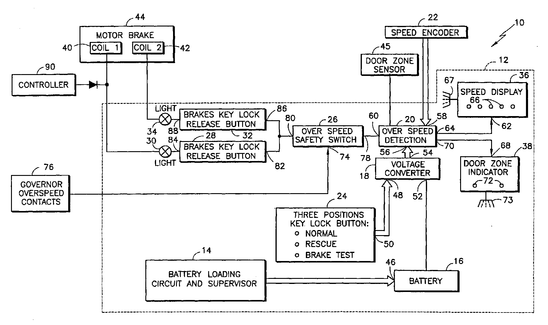
- FIG. 1 is a schematic block diagram of an elevator rescue system embodying the present invention.
-
- Referring to FIG. 1, an elevator rescue system embodying the present invention is generally designated by the
reference number 10. Thesystem 10 includes components enclosed bydashed lines 12 which are preferably centrally located in an emergency and inspection (E & I) service panel easily accessible at an elevator landing. - The
system 10 includes a battery loading andsupervisor circuit 14, a back uppower source 16, such as a DC battery, avoltage converter circuit 18, anoverspeed detection circuit 20, aspeed encoder 22, a rescue enableswitch 24, an optional,overspeed safety switch 26, a firstbrake release switch 28 and firstbrake release indicator 30, an optional, secondbrake release switch 32 and optional, secondbrake release indicator 34, aspeed indicator 36, and adoor zone indicator 38. Thesystem 10 permits a firstmotor brake coil 40 and an optional, secondmotor brake coil 42 of amotor brake 44 associated with an elevator car (not shown) to be repeatedly energized and de-energized to move the elevator car to a desired elevator landing, preferably the nearest elevator landing, during a rescue operation. - The battery loading and
supervisor circuit 14 is a conventional loading circuit which receives power from an AC power source, and is coupled to aninput terminal 46 of theDC battery 16 for charging and monitoring the battery to ensure that the battery maintains its charge. Thebattery 16 preferably is a 12 VDC battery having a capacity for supplying converted electrical power of about 1.3 amperes at about 130 volts DC for a total supply time of up to about four minutes over an operation period (i.e. of uninterrupted and interrupted supply of battery power) of about ten minutes. - The rescue enable
switch 24 is preferably a manually-operated, three position, key lock button that is switchable among three positions: normal operation, rescue operation, and brake test. Thevoltage converter circuit 18, preferably a 12VDC to 130 VDC voltage converter, includes afirst input 48 coupled to anoutput 50 of the rescue enableswitch 24, asecond input 52 coupled to an output of thebattery 16, and anoutput 54. Thevoltage converter circuit 18 is preferably a conventional DC to DC voltage converter which receives a first voltage at itssecond input 52 and generates a second, relatively higher voltage at itsoutput 54 when the voltage converter circuit is enabled by the rescue enableswitch 24. - The
overspeed detection circuit 20 is a conventional processor including afirst input 56 coupled to theoutput 54 of thevoltage converter circuit 18 for receiving electrical power from the battery which has been converted to the second voltage level suitable for powering the first andsecond coils motor brake 44. Theoverspeed detection circuit 20 also includes asecond input 58 for receiving a speed control signal from thespeed encoder 22. - The
speed encoder 22 preferably is a speed encoder, but may be substituted by other types of speed detectors. Thespeed encoder 22 is employed with a conventional elevator machine sheave (not shown) which has an interface where a ring having holes about its diameter (not shown) of, for example, about 120 mm inner diameter and 160 mm outer diameter may be attached to one of the machine sheave flanges for use in providing feedback to the speed encoder. Thespeed encoder 22 preferably includes a horseshoe shaped sensor for sending two light beams through the holes in the ring. The number of light pulses transmitted through the holes of the ring and received by the speed encoder are used by known methods to determine the position of the elevator car along the hoistway. Further, the number of light pulses received by thespeed encoder 22 per unit of time may be used by the speed encoder to generate a speed control signal having a signal magnitude corresponding to the speed of the elevator car. Alternatively, doorzone indicator sensors 45 may be coupled to theoverspeed detection circuit 20 to indicate when the elevator car is within the door zone and is flush with the nearest safe landing for disembarkation. - When the
overspeed detection circuit 20 receives a speed control signal generated by thespeed encoder 22 which is below a predetermined value indicating that the elevator car is either stationary or moving at a safe speed along the hoistway to the desired landing for disembarkation, the overspeed detection circuit passes the electrical power received at itsfirst input 56 to afirst output 60. When the speed control signal reaches a predetermined value indicating that the elevator car has reached a first maximum safe speed, such as about 0.63 meters/second, theoverspeed detection circuit 20 does not pass the electrical power received at itsfirst input 56 to itsfirst output 60. - The
speed indicator 36 has aninput 62 coupled to asecond output 64 of theoverspeed detection circuit 36, and preferably includes a plurality ofvisual indicators speed indicator 36 also includes afirst alarm 67 for audibly sounding an alarm when the elevator car reaches the first maximum safe speed. For example, a single illuminatedvisual indicator 66 might correspond to a stationary or slow speed, two illuminatedvisual indicators motor brake 44 should be either automatically or manually applied to stop the elevator car. - Further, the
visual indicators visual indicator 66 might be initially lit upon elevator movement. If the elevator car is moving upwardly, the nextvisual indicator 66 to be lit might be to the right of the centervisual indicator 66. Conversely, if the elevator car is moving downwardly, the nextvisual indicator 66 to be lit might be to the left of the centervisual indicator 66. Of course, arranging thevisual indicators - The
door zone indicator 38 has aninput 68 coupled to athird output 70 of theoverspeed detection circuit 20, and preferably includes one or two visual indicators 72, 72, such as LED indicators, for visually indicating whether the elevator car is nearly level with a desired elevator landing where trapped passengers on the elevator car may disembark. Preferably, thedoor zone indicator 38 includes a secondaudible alarm 73 for sounding an alarm when the elevator car moves within a door zone. As an example, one of the visual indicators 72 may be illuminated when the floor of the elevator car is generally in a door zone defined as a slight predetermined distance (i.e., within one or two feet) above and/ or below the floor level of the landing employed for the safe exit of passengers from the elevator car. As a further example, the other visual indicator 72 or both visual indicators 72, 72 may be illuminated when the floor of the elevator car is within the door zone and is also relatively flush with the floor level of the desired landing for safe disembarkation. Preferably, the elevator car should be stopped where the lower end of the toe guard of the elevator car is below the floor of the landing. - The
overspeed safety switch 26 optionally may be employed as an additional means for preventing the elevator car from passing a second maximum safe speed which is higher than the first maximum safe speed should theoverspeed detection circuit 20 fail. Theoverspeed safety switch 26 includes acontrol input 74 coupled to conventional governor overspeedcontacts 76 already in place in elevator systems. Theoverspeed safety switch 26 also includes aninput 78 coupled to thefirst output 60 of theoverspeed detection circuit 20, and anoutput 80 for transmitting electrical power to thepower brake coils motor brake 44 when the overspeed safety switch is in a closed state when the elevator car is traveling below the second maximum safe speed. If the governor overspeedcontacts 76 are opened for at least a predetermined time period, such as for example 100 ms, upon the elevator car reaching the second maximum safe speed, the opened governor overspeedcontacts 76 cause theoverspeed safety switch 26 via itscontrol input 74 to be opened, to thereby cut electrical power to themotor brake coils motor brake 44 and stop the elevator car. Theoverspeed safety switch 26 is described in more detail in co-pending U.S. Application file no. OT-4542, filed , and entitled "Remote Storage and Reset of Elevator Overspeed Switch", the disclosure of which is hereby incorporated by reference. - The first
brake release switch 28 includes aninput 82 coupled to theoutput 80 of theoverspeed safety switch 26, and anoutput 84 coupled to thefirst coil 40 of themotor brake 44 via the firstbrake release indicator 30, such as an LED. Likewise, the secondbrake release switch 32 includes aninput 86 coupled to theoutput 80 of theoverspeed safety switch 26, and anoutput 88 coupled to thesecond coil 42 of themotor brake 44 via the secondbrake release indicator 34, such as an LED. Preferably, the first and second brake release switches 28, 32 are resetable, manually-operated, constant pressure switches which must be manually maintained in a closed position to transmit electrical power from thepower source 16 to the first and second motor brake coils 40, 42 of themotor brake 44. - The operation of the present invention embodied in FIG. 1 will now be explained for situations where an elevator car is stopped between floor landings of an elevator hoistway because of a failure of the elevator system, such as, for example, a power failure or broken safety chain. The
system 10 of the present invention is typically employed to move the elevator car up to about eleven meters to the nearest safe elevator landing. The operation of the present invention is to be implemented when the elevator safeties are operating properly and are not engaged with the elevator rails. If the safety chains are not functioning properly, measures must be taken to ensure that it is safe to move the elevator car including ensuring that all hoistway doors are closed, locked, and marked "out of service". A typical rescue scenario is where anelevator controller 90 for driving the first andsecond coils system 10 be independent in operation from theelevator controller 90. - In an emergency situation, the rescue enable
switch 24 located in the E & I servicepanel 12 is switched from normal mode to rescue mode in order to actuate thevoltage converter 38 via itsfirst input 48 in order to convert the voltage level of the electrical power generated by thepower source 16 to a level suitable for energizing the first and second motor brake coils 40, 42. More specifically, the actuatedvoltage converter 18 receives electrical power at itssecond input 52 having a first DC voltage level generated from the back-upbattery 16 which had been previously charged by the battery loading andsupervisor circuit 14 when AC electrical power was available. The electrical power received by thevoltage converter 18 is converted to a second DC voltage level that is preferably higher than the first voltage level in order to energize the first andsecond coils motor brake 44. The first and second brake release switches 28, 32 are then manually closed preferably only by maintaining a constant pressure on these switches. Preferably, the first and second brake release switches 28, 32 are in the form of buttons that are operable upon entering a key thereto so that therescue system 10 is not engagable by unauthorized personnel. - The converted electrical power is received by the
overspeed detector circuit 20 at itsfirst input 56. Meanwhile, thespeed encoder circuit 22 will typically initially transmit a speed control signal to thesecond input 58 of theoverspeed detection circuit 20 indicating that the elevator car is stationary. Because the speed control signal initially has a value below a predetermined value corresponding to the first maximum safe speed of the trapped elevator car, theoverspeed detection circuit 20 will pass the electrical power received at itsfirst input 56 to itsfirst output 60. Theoverspeed detection circuit 20 will also transmit via itssecond output 64 one or more control signals to theinput 62 of thespeed indicator 36 for illuminating one or more of thevisual indicators visual indicators 66 will initially be illuminated. Theoverspeed detection circuit 20 will also transmit via itsthird output 70 one or more control signals to theinput 68 of thedoor zone indicator 38 indicating whether the elevator car is in a door zone and whether the elevator car floor is flush with the floor of a desired landing for passenger disembarkation. - The electrical power at the
first output 60 of theoverspeed detection circuit 20 is transmitted through theoverspeed safety switch 26 which is in a closed state during safe elevator speeds. The electrical power is further passed through the first and second brake release switches 32, 34 which are being maintained in a closed state by maintaining pressure on the switches by a human operator. The electrical power is thus transmitted from thepower source 16 and through the serially connected components including thevoltage converter 18, theoverspeed detection circuit 20, theoverspeed safety switch 26, and through the first and second brake release switches 28, 32 to energize respectively the first and second motor brake coils 40, 42 to thereby release themotor brake 44 to move the elevator car to the desired elevator landing. The first and secondbrake release indicators - If the weight of the elevator car including the passenger weight is higher than that of the elevator counterweight, the elevator car will begin to move downwardly. Conversely, if the weight of the elevator car including the passenger weight is lower than that of the elevator counterweight, the elevator car will begin to move upwardly. Should the weight of the elevator car including the weight of passengers be balanced with that of the counterweight, weight can be added to the elevator car to create an imbalance for moving the car.
- As the elevator car begins to move either upwardly or downwardly to the desired elevator landing for disembarkation, the elevator car speed will progressively increase. The
speed encoder 22 will detect the speed increase and will continually transmit updated speed control signals to the overspeed detection circuit having a value corresponding to the instantaneous speed of the elevator car. Theoverspeed detection circuit 20 will transmit speed information via itssecond output 64 to theinput 62 of thespeed indicator 36 to permit a human operator to determine by means of the number of illuminatedvisual indicators visual indicators system 10 is functioning properly. For example, if all of thevisual indicators power source 16 to the first and second motor brake coils 40, 42. With electrical power cut off from the first and second motor brake coils 40, 42, the coils are de-energized resulting in applying themotor brake 44 to stop the elevator car. - The
overspeed detection circuit 20 will also transmit door zone information via itsthird output 70 to theinput 68 of thedoor zone indicator 38 to permit a human operator to determine by means of the illuminated visual indicators 72, 72 whether the elevator car is within a door zone of the desired elevator landing for safe disembarkation. For example, one of the visual indicators 72 might be illuminated to indicate that the floor of the elevator car is within a safe distance, such as one or two feet, of the floor of the nearest elevator landing, or the other or both of the visual indicators 72, 72 might be illuminated to indicate that the floor of the elevator car is generally flush with the floor of the nearest elevator landing for the safest scenario for passenger disembarkation. When the visual indicators 72, 72 are illuminated, the human operator may then open the first and second brake release switches 28, 32 to de-energize the first and second motor brake coils 40, 42 to thereby apply themotor brake 44 to stop the elevator car. The operator may also close the first and second brake release switches 28, 32 to continue moving the elevator to another landing, such as in cases where the first landing is unsafe or where a mechanic needs to move the elevator car to near the top landing in order to gain access to the elevator machine. - Returning now to the scenario where the rescue enable
switch 24 is set to the rescue position and the first and second brake release switches 28, 32 are manually maintained in a closed position to supply electrical power to the first and second motor brake coils 40, 42, thespeed encoder 22 will generate and transmit generally continuously updated speed control signals to theoverspeed detection circuit 20. When theoverspeed detection circuit 20 receives a speed control signal having a value indicating that the elevator car has reached the first maximum safe speed, the overspeed detection circuit will not pass electrical power from itsfirst input 56 to itsfirst output 60 to thereby automatically cut electrical power to the first and second motor brake coils 40, 42. The de-energized coils 40, 42 results in applying themotor brake 44 to stop the elevator car. Preferably, after a predetermined time period, such as one second, theoverspeed detection circuit 20 automatically resets to a state for passing the electrical power to itsfirst output 60 in order to re-energize the first and second brake coils 40, 42 to thereby release themotor brake 44 and begin moving the elevator car further toward the nearest safe landing for disembarkation. A trade-off thus exists between the automatic feature for preventing elevator speed from becoming dangerously high and a smooth ride to the nearest elevator landing because the elevator car may need to be started and stopped several times before reaching the landing. - Should the
overspeed detection circuit 20 fail in cutting electrical power to the first and second motor brake coils 40, 42, the elevator car will continue to increase in speed beyond the first maximum safe speed. Should thespeed indicator 36 still function properly, the human operator will be able to see from thevisual indicators motor brake 44 and stop the elevator car. Should thespeed indicator 36 fail along with theoverspeed detection circuit 60, once the elevator car reaches a higher, second maximum safe speed, the governor overspeedcontacts 76 forming part of the conventional elevator system will automatically open theoverspeed safety switch 26 to cut off electrical power to the first and second motor brake coils 40, 42 so as to apply themotor brake 44 and stop the elevator car. Preferably, theoverspeed safety switch 26 is resetable in order to resume energization of the first and second motor coils 40, 42. - The
rescue system 10 may also be used to test whether a single motor brake shoe associated with a motor brake coil will stop the elevator car. In this situation, the rescue enableswitch 24 is switched to the brake test position which disables the overspeed detection circuit. The power to theelevator controller 90 is cut, while one of the first and second brake release switches 28, 32 is maintained in a closed state in order to energize a respective one of the motor brake coils 40, 42 and thus maintain one of the brake shoes associated with the coils in a released state in order to determine if only one of the brake shoes is sufficient to stop the elevator car should the other shoe fail. - An advantage of the present invention is that the
system 10 uses existing components to provide a low cost, reliable way for safely moving a trapped elevator car to the nearest safe landing for passenger disembarkation. - A second advantage of the present invention is that the overspeed detection circuit is automatic and thus does not rely on human oversight for slowing the elevator car before it reaches an unsafe speed.
- A third advantage of the present invention is that the
overspeed safety switch 26 provides an additional level of safety should theoverspeed detection circuit 20 fail for better ensuring that the elevator car is automatically stopped when reaching maximum safe speeds. Thus experienced elevator technicians need not be called so as to cause delay in freeing trapped passengers. Personnel with little or no elevator technical training, such as a concierge or security guard that is already on-hand, may safely operate the present invention and thereby save valuable time in freeing the passengers. - A fourth advantage of the present invention is that the visual indicators provide yet additional safety by permitting a human operator to manually stop the elevator car upon reaching excessive speed.
- A fifth advantage of the present invention is that the
system 10 should secure the release of trapped passengers within fifteen minutes of beginning the rescue operation by eliminating the need to contact and wait for the arrival of elevator technicians. - Although this invention has been shown and described with respect to an exemplary embodiment thereof, it should be understood by those skilled in the art that the foregoing and various other changes, omissions, and additions in the form and detail thereof may be made therein without departing from the spirit and scope of the invention. For example, the system may be employed by energizing and de-energizing only one motor coil. The speed and door zone indicators may take other forms such as digital numbers indicating elevator car speed and distance from an elevator landing. Further, other speed detectors may be substituted for the speed encoder. Accordingly, the present invention as shown and described in the exemplary embodiment has been presented by way of illustration rather than limitation.
Claims (17)
- Method for rescuing trapped passengers in an elevator car of an elevator, including the following steps:(a) switching a rescue enable switch (24) to permit transmission of electrical power from a power source (16) of back-up electrical power to a motor brake coil (40,42) of the elevator car such that the energized coil (40,41) releases the motor brake (44) to move the car to a desired landing;(b) measuring the speed of the elevator car and generating a speed control signal corresponding to the speed of the car;(c) monitoring the speed control signal for an overspeed condition and transmitting electrical power to the motor brake coil (40,41) when the speed control signal is below a predetermined value and applying the motor brake (44) for stopping the elevator car when the speed control signal becomes higher than a predetermined value.
- Method according to claim 1, wherein the step of transmitting the electrical power to the motor brake coil (40, 41) requires closing of a manually operated brake release switch (28,32).
- Method according to claim 1 or 2, wherein the step of monitoring the speed control signal for an overspeed condition is conducted only when the rescue enable switch (24) has been switched to a closed position.
- Method according to any of claims 1 to 3, further including the step of indicating approaching to a door zone and displaying when the elevator car is generally level with a desired elevator landing.
- Method according to any of claims 1 to 4, further including the step of inverting the voltage as provided by the power source (16) to a predetermined voltage level for actuating the motor brake coil (24).
- Method according to claim 1, wherein the power source (16) is a DC power source an provides a first voltage level, and wherein the voltage is inverted from said first voltage level to a higher second DC voltage level.
- Method according to claim 6, wherein the step of inverting the voltage inverts the 12VDC of the power source to 130VDC.
- Method according to any of claims 1 to 7, further including the step of monitoring governor overspeed contacts of the elevator for resetably opening an overspeed safety switch (26), when the governor overspeed contacts are opened for a predetermined period of time, and transmitting electrical power to actuate the motor brake coil (40,42) for releasing the brake during rescue operations.
- Method according to any of claims 1 to 8, including the step of switching the rescue enable switch (24) to a second position for testing one of two motor brake shoes associated with associated motor brake coils (40,42), the rescue enable switch (24) in the brake test position disabling the overspeed detection circuit (20) and further including a additionally manually-operated brake release switch (28,32) having a input and an output, the input being coupled to the output of the overspeed detection circuit (20) and the output to a second motor brake coil (40,42) such that when the rescue enable switch (24) is in the second position during a brake test, one of the brake release switches (28,32) is closeable for preventing one of the associated shoes of the motor brake (44) from engaging when the elevator controller is disabled to determine whether a single brake shoe will stop the elevator car.
- Method according to any of claims 1 to 9, further including the step of indicating when the elevator car reaches a predetermined maximum safe speed.
- Method according to claim 10, further including to visually indicate when the elevator car reaches a predetermined maximum safe speed.
- Method according to claim 10, further including to indicate an audible alarm (67) when the elevator car reaches a predetermined maximum safe speed.
- Method according to any of claims 4 to 12, wherein the step of indicating approaching to a door zone includes the step of receiving the door zone indication signals from at least one door zone sensor (45) for determining when the the elevator car reaches a door zone of a landing for safe disembarkation of passengers.
- Method according to any of claims 4 to 13, further including visually indicating when the elevator car reaches a door zone of a landing for safe disembarkation of passengers.
- Method according to any of claims 4 to 13, further including to indicate an audible alarm (67) when the elevator car reaches a door zone of a landing for safe disembarkation of passengers.
- Method according to any of claims 1 to 15, wherein the step of monitoring the speed control signal for an overspeed condition is conducted by an overspeed detection circuit (20) and further including the step of actuating the overspeed detection circuit (20) when the rescue enable switch (24) is closed.
- Method according to any of claims 1 to 16, wherein the measuring the speed of the elevator car includes indicating to the overspeed detection circuit (20) the direction of the elevator car movement and reaching a predetermined maximum safe speed.
Applications Claiming Priority (3)
| Application Number | Priority Date | Filing Date | Title |
|---|---|---|---|
| US09/277,495 US6196355B1 (en) | 1999-03-26 | 1999-03-26 | Elevator rescue system |
| US277495 | 1999-03-26 | ||
| EP00921411A EP1165424B1 (en) | 1999-03-26 | 2000-03-20 | Elevator rescue system |
Related Parent Applications (2)
| Application Number | Title | Priority Date | Filing Date |
|---|---|---|---|
| EP00921411.5 Division | 2000-03-20 | ||
| EP00921411A Division EP1165424B1 (en) | 1999-03-26 | 2000-03-20 | Elevator rescue system |
Publications (2)
| Publication Number | Publication Date |
|---|---|
| EP1369372A1 true EP1369372A1 (en) | 2003-12-10 |
| EP1369372B1 EP1369372B1 (en) | 2005-05-25 |
Family
ID=23061129
Family Applications (2)
| Application Number | Title | Priority Date | Filing Date |
|---|---|---|---|
| EP00921411A Expired - Lifetime EP1165424B1 (en) | 1999-03-26 | 2000-03-20 | Elevator rescue system |
| EP03018316A Expired - Lifetime EP1369372B1 (en) | 1999-03-26 | 2000-03-20 | Elevator rescue system |
Family Applications Before (1)
| Application Number | Title | Priority Date | Filing Date |
|---|---|---|---|
| EP00921411A Expired - Lifetime EP1165424B1 (en) | 1999-03-26 | 2000-03-20 | Elevator rescue system |
Country Status (11)
| Country | Link |
|---|---|
| US (2) | US6196355B1 (en) |
| EP (2) | EP1165424B1 (en) |
| JP (1) | JP4530546B2 (en) |
| KR (2) | KR100658017B1 (en) |
| CN (2) | CN1191983C (en) |
| BR (1) | BRPI0009351B1 (en) |
| DE (2) | DE60020411T2 (en) |
| ES (2) | ES2204558T3 (en) |
| PT (2) | PT1369372E (en) |
| TW (1) | TW458941B (en) |
| WO (1) | WO2000058195A1 (en) |
Cited By (5)
| Publication number | Priority date | Publication date | Assignee | Title |
|---|---|---|---|---|
| CN102295203A (en) * | 2011-08-19 | 2011-12-28 | 上海新时达电气股份有限公司 | Elevator system |
| RU2490201C2 (en) * | 2008-08-15 | 2013-08-20 | Отис Элевэйтор Компани | Elevator and mounted electric power supply system with extra power supply control means |
| US8939262B2 (en) | 2009-03-16 | 2015-01-27 | Otis Elevator Company | Elevator over-acceleration and over-speed protection system |
| US11261055B2 (en) | 2017-09-15 | 2022-03-01 | Otis Elevator Company | Elevator emergency stop systems |
| EP4095081A1 (en) * | 2021-05-28 | 2022-11-30 | Otis Elevator Company | Elevator systems |
Families Citing this family (78)
| Publication number | Priority date | Publication date | Assignee | Title |
|---|---|---|---|---|
| DE69921106T2 (en) * | 1999-01-25 | 2005-11-24 | Mitsubishi Denki K.K. | CONTROL DEVICE FOR ELEVATOR BRAKE |
| SG85215A1 (en) * | 1999-10-08 | 2001-12-19 | Inventio Ag | Safety circuit for an elevator installation |
| CN100407545C (en) * | 1999-11-17 | 2008-07-30 | 富士达株式会社 | AC elevator power supply unit |
| SG100645A1 (en) * | 2000-03-31 | 2003-12-26 | Inventio Ag | Auxiliary device for displacing a payload receptacle of a lift and device for monitoring the position and the movement of a cage in a shaft of a lift |
| JP5155505B2 (en) * | 2000-04-27 | 2013-03-06 | インベンテイオ・アクテイエンゲゼルシヤフト | Elevator passenger evacuation device |
| US6892862B2 (en) * | 2000-07-29 | 2005-05-17 | Alpha Getriebebau Gmbh | Elevator car with a driving pulley driving machine integrated therein |
| US6848544B2 (en) * | 2001-01-26 | 2005-02-01 | Inventio Ag | Method and equipment for the evacuation of lift passengers |
| US6516922B2 (en) * | 2001-05-04 | 2003-02-11 | Gregory Shadkin | Self-generating elevator emergency power source |
| US6557670B2 (en) * | 2001-07-17 | 2003-05-06 | Jiun Jyh Wang | Double brake protection device for elevator |
| US6827182B2 (en) * | 2001-10-17 | 2004-12-07 | Mitsubishi Denki Kabushiki Kaisha | Elevator controller |
| US6847292B2 (en) * | 2001-12-20 | 2005-01-25 | Inventio Ag | Method and device for remote unlocking of an access door of a building with an elevator |
| JP2004203623A (en) * | 2002-12-23 | 2004-07-22 | Inventio Ag | Emergency evacuation method and system for person in building and modernization method for existing building using system |
| WO2004083090A1 (en) * | 2003-03-18 | 2004-09-30 | Mitsubishi Denki Kabushiki Kaisha | Emergency stop device for elevator |
| BRPI0318536B1 (en) * | 2003-10-07 | 2015-10-13 | Otis Elevator Co | electric lift rescue system |
| RU2328438C2 (en) * | 2003-10-07 | 2008-07-10 | Отис Элевейтэ Кампэни, США | Hoist and method of saving operation incorportated in hoisting-and-transport equipment (versions) |
| KR100951518B1 (en) * | 2003-10-07 | 2010-04-07 | 오티스 엘리베이터 컴파니 | Emergency stop for ropeless elevators with remote reset |
| US7097001B2 (en) * | 2003-11-12 | 2006-08-29 | Inventio Ag | Elevator car door movement restrictor |
| CN100540443C (en) * | 2004-02-18 | 2009-09-16 | 王秋楠 | Linear driving control device for auxiliary lifting of lifter |
| WO2005105647A1 (en) * | 2004-04-27 | 2005-11-10 | Mitsubishi Denki Kabushiki Kaisha | Elevator apparatus |
| US7350626B2 (en) | 2004-10-20 | 2008-04-01 | Otis Elevator Company | Power-on-reset of elevator controllers |
| FR2880009B1 (en) | 2004-12-27 | 2008-07-25 | Leroy Somer Moteurs | SAFETY DEVICE FOR ELEVATOR |
| WO2006074688A1 (en) * | 2005-01-11 | 2006-07-20 | Otis Elevator Company | Elevator including elevator rescue system |
| US7434664B2 (en) * | 2005-03-08 | 2008-10-14 | Kone Corporation | Elevator brake system method and control |
| US8944217B2 (en) * | 2005-11-04 | 2015-02-03 | Sky Climber, Llc | Suspension work platform hoist system with communication system |
| JP5079517B2 (en) * | 2005-11-25 | 2012-11-21 | 三菱電機株式会社 | Elevator emergency stop system |
| JP5151153B2 (en) * | 2006-12-28 | 2013-02-27 | 三菱電機株式会社 | Elevator brake test apparatus and test method thereof |
| WO2008117423A1 (en) * | 2007-03-27 | 2008-10-02 | Mitsubishi Electric Corporation | Brake device for elevator |
| US8267224B2 (en) * | 2007-07-17 | 2012-09-18 | Inventio Ag | Special operating mode for stopping an elevator car |
| CN101765557B (en) * | 2007-07-25 | 2012-07-25 | 三菱电机株式会社 | Elevator device |
| KR20110016984A (en) * | 2008-06-03 | 2011-02-18 | 오티스 엘리베이터 컴파니 | (Electrical) single brake shoe test for elevators |
| JP2012532078A (en) | 2009-06-30 | 2012-12-13 | オーチス エレベータ カンパニー | Gravity-driven start-up phase in power rescue elevator rescue operations |
| KR20120032019A (en) * | 2009-07-02 | 2012-04-04 | 오티스 엘리베이터 컴파니 | Elevator rescue system |
| SE534114C2 (en) * | 2009-09-14 | 2011-05-03 | Scania Cv Ab | Method and system for starting a vehicle |
| DE102010038432A1 (en) * | 2010-07-26 | 2012-01-26 | Thyssenkrupp Aufzugswerke Gmbh | Elevator control device |
| GB201017711D0 (en) * | 2010-10-20 | 2010-12-01 | Sonitor Technologies As | Position determination system |
| US9637349B2 (en) | 2010-11-04 | 2017-05-02 | Otis Elevator Company | Elevator brake including coaxially aligned first and second brake members |
| FI122425B (en) * | 2010-11-18 | 2012-01-31 | Kone Corp | Fuse circuit for power supply, elevator system and procedure |
| CN102126660A (en) * | 2011-02-17 | 2011-07-20 | 上海微频莱机电科技有限公司 | Electronic type overspeed detecting device |
| WO2013066321A1 (en) * | 2011-11-02 | 2013-05-10 | Otis Elevator Company | Brake torque monitoring and health assessment |
| CN102372219A (en) * | 2011-11-28 | 2012-03-14 | 苏州富士电梯有限公司 | Manual rescue device of motor driven elevator |
| JP2013119436A (en) * | 2011-12-06 | 2013-06-17 | Hitachi Ltd | Elevator apparatus and method for controlling the same |
| CN102674120A (en) * | 2012-05-25 | 2012-09-19 | 巨人通力电梯有限公司 | Domestic machine-room-less lift driving cabinet |
| US9573791B2 (en) * | 2013-02-13 | 2017-02-21 | Kone Corporation | Elevators and elevator arrangements with maintenance cabinet in landing wall |
| FR3002766B1 (en) * | 2013-03-01 | 2015-04-10 | Leroy Somer Moteurs | BRAKE CONTROL SYSTEM FOR ELEVATOR |
| FR3004872B1 (en) * | 2013-04-17 | 2017-05-05 | Moteurs Leroy-Somer | DEVICE FOR MONITORING A CURRENT BRAKE. |
| FI124268B (en) * | 2013-05-29 | 2014-05-30 | Kone Corp | Procedure and apparatus for carrying out rescue operations |
| CN103303761B (en) * | 2013-06-28 | 2015-06-10 | 梁广强 | Acoustic control emergency rescue system of elevator |
| JP6177629B2 (en) * | 2013-08-30 | 2017-08-09 | 株式会社日立製作所 | Electronic safety elevator |
| FI125887B (en) * | 2015-01-16 | 2016-03-31 | Kone Corp | Elevator rescue device |
| WO2016113456A1 (en) * | 2015-01-16 | 2016-07-21 | Kone Corporation | A rescue apparatus and an elevator |
| EP3072842B1 (en) | 2015-03-23 | 2019-09-25 | Kone Corporation | Elevator rescue system |
| CN107835780B (en) * | 2015-07-22 | 2019-05-21 | 三菱电机株式会社 | elevator installation |
| CN106395568B (en) * | 2015-07-31 | 2020-05-05 | 奥的斯电梯公司 | Elevator recovery car |
| CN107848734B (en) | 2015-08-07 | 2021-06-22 | 奥的斯电梯公司 | Rescue control and method of operating an elevator system including a permanent magnet (PM) synchronous motor drive system |
| EP3331794A1 (en) | 2015-08-07 | 2018-06-13 | Otis Elevator Company | Elevator system including a permanent magnet (pm) synchronous motor drive system |
| ES2694854T3 (en) * | 2015-08-18 | 2018-12-27 | Kone Corporation | Method to move an elevator car |
| CN105236223B (en) * | 2015-09-23 | 2018-01-02 | 日立电梯(中国)有限公司 | inertia measuring system and method |
| BR112018008005A2 (en) * | 2015-11-02 | 2018-10-30 | Inventio Ag | stepped braking of an elevator |
| US9809418B2 (en) * | 2016-02-29 | 2017-11-07 | Otis Elevator Company | Advanced smooth rescue operation |
| US10919730B2 (en) * | 2016-03-18 | 2021-02-16 | Otis Elevator Company | Management of mutiple coil brake for elevator system |
| US10252884B2 (en) * | 2016-04-05 | 2019-04-09 | Otis Elevator Company | Wirelessly powered elevator electronic safety device |
| EP3243784B1 (en) * | 2016-05-11 | 2019-01-30 | Kone Corporation | Arrangement for releasing the operating brake of an elevator |
| JP6655489B2 (en) * | 2016-07-06 | 2020-02-26 | 株式会社日立製作所 | Elevator |
| WO2018020542A1 (en) * | 2016-07-25 | 2018-02-01 | 株式会社日立製作所 | Elevator control device |
| EP3299326B1 (en) * | 2016-08-24 | 2024-09-25 | Otis Elevator Company | Communication with a trapped passenger in a transportation system |
| EP3321224A1 (en) * | 2016-11-10 | 2018-05-16 | Kone Corporation | Electrical rescue system for rescuing passengers from an elevator car, a tool for the same, and a corresponding method |
| US20180162693A1 (en) * | 2016-12-13 | 2018-06-14 | Otis Elevator Company | Speed detection means for elevator or counterweight |
| CN106829673B (en) * | 2017-04-07 | 2022-08-05 | 上海爱登堡电梯集团股份有限公司 | Machine room-less elevator with emergency rescue device |
| DK3403971T3 (en) * | 2017-05-19 | 2021-01-25 | Kone Corp | PROCEDURE FOR PERFORMING A MANUAL DRIVE IN AN ELEVATOR AFTER POWER DISCONNECTION |
| DK3483106T3 (en) | 2017-11-08 | 2020-08-31 | Kone Corp | ELEVATOR AUTOMATIC AND MANUAL RESCUE OPERATION |
| CN107857180A (en) * | 2017-11-28 | 2018-03-30 | 广东省特种设备检测研究院珠海检测院 | A kind of detecting system and method for accidental movement of elevator cage defencive function |
| US11040854B2 (en) | 2018-03-03 | 2021-06-22 | Otis Elevator Company | Resetting governor sub-systems |
| ES2882042T3 (en) * | 2018-03-16 | 2021-12-01 | Otis Elevator Co | Automatic rescue operation in an elevator system |
| EP3613691B1 (en) * | 2018-08-20 | 2021-10-27 | Inventio AG | Maintenance patch panel and lift control for controlled braking movements of a lift cabin |
| CN110963387B (en) | 2018-09-29 | 2022-06-10 | 奥的斯电梯公司 | Overspeed protection switch, speed limiter assembly and elevator system |
| CN111498635A (en) * | 2020-04-16 | 2020-08-07 | 柯凡尼电梯(上海)有限公司 | Remote autonomous rescue system for trapped people in household elevators |
| TWI823303B (en) * | 2022-03-23 | 2023-11-21 | 辛耘企業股份有限公司 | Lifting equipment with anti-drop function and first braking device |
| EP4332042B1 (en) * | 2022-09-05 | 2026-04-29 | Otis Elevator Company | Setting a rescue time period |
Citations (5)
| Publication number | Priority date | Publication date | Assignee | Title |
|---|---|---|---|---|
| US4506766A (en) * | 1983-08-17 | 1985-03-26 | Mitsubishi Denki Kabushiki Kaisha | Method and apparatus for fault time operating of an elevator _ |
| US4533021A (en) * | 1982-11-15 | 1985-08-06 | Perez Marcelino De La | Lift exit emergency safety system |
| JPH04189284A (en) * | 1990-11-22 | 1992-07-07 | Hitachi Ltd | Mischievous oscillation preventing device for elevator |
| US5526902A (en) * | 1993-09-01 | 1996-06-18 | Gausachs; Miguel | Safety device for lifts stopped between floors |
| DE19754034A1 (en) * | 1997-12-05 | 1999-06-10 | Hopmann Maschinenfabrik Gmbh L | Lift brake with manual release |
Family Cites Families (19)
| Publication number | Priority date | Publication date | Assignee | Title |
|---|---|---|---|---|
| US3792759A (en) * | 1972-12-22 | 1974-02-19 | Westinghouse Electric Corp | Elevator system |
| JPS6013950B2 (en) * | 1976-07-05 | 1985-04-10 | 三菱電機株式会社 | Elevator emergency stop device |
| JPS6050706B2 (en) * | 1977-08-17 | 1985-11-09 | 三菱電機株式会社 | Automatic landing device in case of elevator power outage |
| JPS5336851A (en) * | 1977-09-28 | 1978-04-05 | Hitachi Ltd | Device for automatically stopping elevator cage at floor upon electric power service interruption |
| JPS56103077A (en) * | 1980-01-21 | 1981-08-17 | Mitsubishi Electric Corp | Emergency driving device for elevator |
| JPS60119073U (en) * | 1984-01-19 | 1985-08-12 | 三菱電機株式会社 | Rescue operation device for drum type elevator |
| JPS60262783A (en) * | 1984-06-12 | 1985-12-26 | 三菱電機株式会社 | Automatic floor reaching device on service interruption of alternating current elevator |
| JPS63218491A (en) * | 1987-03-03 | 1988-09-12 | 株式会社東芝 | Rescue operating device for winding drum type elevator |
| JPH0624664A (en) * | 1992-07-07 | 1994-02-01 | Hitachi Building Syst Eng & Service Co Ltd | Emergency rescue operating device for elevator |
| FI95021C (en) * | 1993-06-08 | 1995-12-11 | Kone Oy | Method and apparatus for triggering an elevator gripping device |
| FI99109C (en) * | 1994-11-29 | 1997-10-10 | Kone Oy | Emergency Power System |
| FI97718C (en) * | 1995-03-24 | 1997-02-10 | Kone Oy | Elevator motor emergency drive |
| JP3309648B2 (en) * | 1995-06-22 | 2002-07-29 | 三菱電機株式会社 | Elevator control device |
| CN1063726C (en) * | 1996-07-09 | 2001-03-28 | 王秋楠 | Elevator safety release device |
| FI103498B (en) * | 1996-09-05 | 1999-07-15 | Kone Corp | Arrangement for opening the brake of the lift machinery |
| KR100214686B1 (en) * | 1997-04-10 | 1999-08-02 | 이종수 | Rescue operation apparatus with power-factor improvement system for elevator |
| US6039151A (en) * | 1997-04-25 | 2000-03-21 | Inventio Ag | Backup apparatus for a hydraulic elevator brake control |
| US6021872A (en) * | 1997-05-28 | 2000-02-08 | Otis Elevator Company | Remote brake release mechanism for an elevator machine |
| US6161653A (en) * | 1998-12-22 | 2000-12-19 | Otis Elevator Company | Ropeless governor mechanism for an elevator car |
-
1999
- 1999-03-26 US US09/277,495 patent/US6196355B1/en not_active Expired - Lifetime
-
2000
- 2000-03-20 EP EP00921411A patent/EP1165424B1/en not_active Expired - Lifetime
- 2000-03-20 DE DE60020411T patent/DE60020411T2/en not_active Expired - Lifetime
- 2000-03-20 WO PCT/US2000/007391 patent/WO2000058195A1/en not_active Ceased
- 2000-03-20 CN CNB008078467A patent/CN1191983C/en not_active Expired - Lifetime
- 2000-03-20 PT PT03018316T patent/PT1369372E/en unknown
- 2000-03-20 ES ES00921411T patent/ES2204558T3/en not_active Expired - Lifetime
- 2000-03-20 CN CNB2004101001582A patent/CN100404404C/en not_active Expired - Lifetime
- 2000-03-20 ES ES03018316T patent/ES2245430T3/en not_active Expired - Lifetime
- 2000-03-20 KR KR1020067017166A patent/KR100658017B1/en not_active Expired - Lifetime
- 2000-03-20 EP EP03018316A patent/EP1369372B1/en not_active Expired - Lifetime
- 2000-03-20 DE DE60004501T patent/DE60004501T2/en not_active Expired - Lifetime
- 2000-03-20 PT PT00921411T patent/PT1165424E/en unknown
- 2000-03-20 BR BRPI0009351A patent/BRPI0009351B1/en active IP Right Grant
- 2000-03-20 KR KR1020017012252A patent/KR100650490B1/en not_active Expired - Lifetime
- 2000-03-20 JP JP2000607908A patent/JP4530546B2/en not_active Expired - Fee Related
- 2000-03-31 TW TW089105483A patent/TW458941B/en not_active IP Right Cessation
- 2000-07-20 US US09/620,669 patent/US6269910B1/en not_active Expired - Lifetime
Patent Citations (5)
| Publication number | Priority date | Publication date | Assignee | Title |
|---|---|---|---|---|
| US4533021A (en) * | 1982-11-15 | 1985-08-06 | Perez Marcelino De La | Lift exit emergency safety system |
| US4506766A (en) * | 1983-08-17 | 1985-03-26 | Mitsubishi Denki Kabushiki Kaisha | Method and apparatus for fault time operating of an elevator _ |
| JPH04189284A (en) * | 1990-11-22 | 1992-07-07 | Hitachi Ltd | Mischievous oscillation preventing device for elevator |
| US5526902A (en) * | 1993-09-01 | 1996-06-18 | Gausachs; Miguel | Safety device for lifts stopped between floors |
| DE19754034A1 (en) * | 1997-12-05 | 1999-06-10 | Hopmann Maschinenfabrik Gmbh L | Lift brake with manual release |
Non-Patent Citations (1)
| Title |
|---|
| PATENT ABSTRACTS OF JAPAN vol. 016, no. 510 (M - 1328) 21 October 1992 (1992-10-21) * |
Cited By (7)
| Publication number | Priority date | Publication date | Assignee | Title |
|---|---|---|---|---|
| RU2490201C2 (en) * | 2008-08-15 | 2013-08-20 | Отис Элевэйтор Компани | Elevator and mounted electric power supply system with extra power supply control means |
| US8939262B2 (en) | 2009-03-16 | 2015-01-27 | Otis Elevator Company | Elevator over-acceleration and over-speed protection system |
| CN102295203A (en) * | 2011-08-19 | 2011-12-28 | 上海新时达电气股份有限公司 | Elevator system |
| US11261055B2 (en) | 2017-09-15 | 2022-03-01 | Otis Elevator Company | Elevator emergency stop systems |
| EP4095081A1 (en) * | 2021-05-28 | 2022-11-30 | Otis Elevator Company | Elevator systems |
| US20220380175A1 (en) * | 2021-05-28 | 2022-12-01 | Otis Elevator Company | Elevator systems |
| US12595155B2 (en) * | 2021-05-28 | 2026-04-07 | Otis Elevator Company | Elevator systems |
Also Published As
| Publication number | Publication date |
|---|---|
| DE60004501D1 (en) | 2003-09-18 |
| TW458941B (en) | 2001-10-11 |
| PT1165424E (en) | 2003-12-31 |
| BRPI0009351B1 (en) | 2016-05-03 |
| EP1369372B1 (en) | 2005-05-25 |
| DE60020411T2 (en) | 2006-02-02 |
| DE60020411D1 (en) | 2005-06-30 |
| CN1191983C (en) | 2005-03-09 |
| EP1165424B1 (en) | 2003-08-13 |
| KR20020000552A (en) | 2002-01-05 |
| KR100658017B1 (en) | 2006-12-15 |
| ES2245430T3 (en) | 2006-01-01 |
| CN1351571A (en) | 2002-05-29 |
| KR100650490B1 (en) | 2006-11-28 |
| WO2000058195A1 (en) | 2000-10-05 |
| PT1369372E (en) | 2005-07-29 |
| CN100404404C (en) | 2008-07-23 |
| JP2002540043A (en) | 2002-11-26 |
| EP1165424A1 (en) | 2002-01-02 |
| ES2204558T3 (en) | 2004-05-01 |
| BR0009351A (en) | 2002-01-29 |
| KR20060107588A (en) | 2006-10-13 |
| JP4530546B2 (en) | 2010-08-25 |
| HK1076787A1 (en) | 2006-01-27 |
| CN1616336A (en) | 2005-05-18 |
| DE60004501T2 (en) | 2004-03-25 |
| US6269910B1 (en) | 2001-08-07 |
| US6196355B1 (en) | 2001-03-06 |
Similar Documents
| Publication | Publication Date | Title |
|---|---|---|
| EP1369372B1 (en) | Elevator rescue system | |
| KR100435987B1 (en) | Elevator maintenance/operation apparatus | |
| JP4879911B2 (en) | Elevator with elevator rescue system | |
| JP2002274766A (en) | Elevator system, and post-attachment method for elevator shaft monitoring device | |
| JPWO2010058453A1 (en) | Elevator equipment | |
| US20010035315A1 (en) | Device for the evacuation of elevator passengers | |
| EP3960673A1 (en) | Elevator systems | |
| CN106477416B (en) | Method for moving an elevator car and elevator | |
| US6538574B2 (en) | Device for signaling the position of an elevator car in the case of passenger evacuation | |
| HK1076787B (en) | Method for elevator rescuing and elevator having rescue system | |
| KR20230151106A (en) | elevator device | |
| JP6578066B2 (en) | Elevator control device | |
| KR200429753Y1 (en) | Elevator Auto Rescue Driving Circuit | |
| KR20230150355A (en) | elevator device | |
| HK1117807B (en) | Elevator including elevator rescue system and rescue method | |
| JPH04361961A (en) | Elevator cage location indicating device |
Legal Events
| Date | Code | Title | Description |
|---|---|---|---|
| PUAI | Public reference made under article 153(3) epc to a published international application that has entered the european phase |
Free format text: ORIGINAL CODE: 0009012 |
|
| 17P | Request for examination filed |
Effective date: 20030812 |
|
| AC | Divisional application: reference to earlier application |
Ref document number: 1165424 Country of ref document: EP Kind code of ref document: P |
|
| AK | Designated contracting states |
Kind code of ref document: A1 Designated state(s): DE ES FR IT PT |
|
| RIN1 | Information on inventor provided before grant (corrected) |
Inventor name: BLACKABY, BARRY, G Inventor name: SIRIGU, GERARD Inventor name: SCHRODER-BRUMLOOP,HELMUT L. Inventor name: FARGO, RICHARD N Inventor name: BARNA, JOSEPH |
|
| RIN1 | Information on inventor provided before grant (corrected) |
Inventor name: BLACKABY, BARRY, G Inventor name: BARNA, JOSEPH Inventor name: SCHRODER-BRUMLOOP,HELMUT L. Inventor name: SIRIGU, GERARD Inventor name: FARGO, RICHARD N |
|
| 17Q | First examination report despatched |
Effective date: 20040316 |
|
| AKX | Designation fees paid |
Designated state(s): DE ES FR IT PT |
|
| GRAP | Despatch of communication of intention to grant a patent |
Free format text: ORIGINAL CODE: EPIDOSNIGR1 |
|
| GRAS | Grant fee paid |
Free format text: ORIGINAL CODE: EPIDOSNIGR3 |
|
| GRAA | (expected) grant |
Free format text: ORIGINAL CODE: 0009210 |
|
| AC | Divisional application: reference to earlier application |
Ref document number: 1165424 Country of ref document: EP Kind code of ref document: P |
|
| AK | Designated contracting states |
Kind code of ref document: B1 Designated state(s): DE ES FR IT PT |
|
| REF | Corresponds to: |
Ref document number: 60020411 Country of ref document: DE Date of ref document: 20050630 Kind code of ref document: P |
|
| REG | Reference to a national code |
Ref country code: PT Ref legal event code: SC4A Effective date: 20050608 |
|
| REG | Reference to a national code |
Ref country code: ES Ref legal event code: FG2A Ref document number: 2245430 Country of ref document: ES Kind code of ref document: T3 |
|
| ET | Fr: translation filed | ||
| PLBE | No opposition filed within time limit |
Free format text: ORIGINAL CODE: 0009261 |
|
| STAA | Information on the status of an ep patent application or granted ep patent |
Free format text: STATUS: NO OPPOSITION FILED WITHIN TIME LIMIT |
|
| 26N | No opposition filed |
Effective date: 20060228 |
|
| PGFP | Annual fee paid to national office [announced via postgrant information from national office to epo] |
Ref country code: PT Payment date: 20140320 Year of fee payment: 15 |
|
| REG | Reference to a national code |
Ref country code: PT Ref legal event code: MM4A Free format text: LAPSE DUE TO NON-PAYMENT OF FEES Effective date: 20150921 |
|
| PG25 | Lapsed in a contracting state [announced via postgrant information from national office to epo] |
Ref country code: PT Free format text: LAPSE BECAUSE OF NON-PAYMENT OF DUE FEES Effective date: 20150921 |
|
| REG | Reference to a national code |
Ref country code: FR Ref legal event code: PLFP Year of fee payment: 17 |
|
| PGFP | Annual fee paid to national office [announced via postgrant information from national office to epo] |
Ref country code: IT Payment date: 20160224 Year of fee payment: 17 |
|
| REG | Reference to a national code |
Ref country code: FR Ref legal event code: PLFP Year of fee payment: 18 |
|
| REG | Reference to a national code |
Ref country code: DE Ref legal event code: R082 Ref document number: 60020411 Country of ref document: DE Representative=s name: SCHMITT-NILSON SCHRAUD WAIBEL WOHLFROM PATENTA, DE |
|
| REG | Reference to a national code |
Ref country code: FR Ref legal event code: PLFP Year of fee payment: 19 |
|
| PG25 | Lapsed in a contracting state [announced via postgrant information from national office to epo] |
Ref country code: IT Free format text: LAPSE BECAUSE OF NON-PAYMENT OF DUE FEES Effective date: 20170320 |
|
| PGFP | Annual fee paid to national office [announced via postgrant information from national office to epo] |
Ref country code: DE Payment date: 20190219 Year of fee payment: 20 |
|
| PGFP | Annual fee paid to national office [announced via postgrant information from national office to epo] |
Ref country code: FR Payment date: 20190220 Year of fee payment: 20 |
|
| PGFP | Annual fee paid to national office [announced via postgrant information from national office to epo] |
Ref country code: ES Payment date: 20190401 Year of fee payment: 20 |
|
| REG | Reference to a national code |
Ref country code: DE Ref legal event code: R071 Ref document number: 60020411 Country of ref document: DE |
|
| REG | Reference to a national code |
Ref country code: ES Ref legal event code: FD2A Effective date: 20201002 |
|
| PG25 | Lapsed in a contracting state [announced via postgrant information from national office to epo] |
Ref country code: ES Free format text: LAPSE BECAUSE OF EXPIRATION OF PROTECTION Effective date: 20200321 |