EP1369086A1 - Breast carcinoma detector - Google Patents
Breast carcinoma detector Download PDFInfo
- Publication number
- EP1369086A1 EP1369086A1 EP02705140A EP02705140A EP1369086A1 EP 1369086 A1 EP1369086 A1 EP 1369086A1 EP 02705140 A EP02705140 A EP 02705140A EP 02705140 A EP02705140 A EP 02705140A EP 1369086 A1 EP1369086 A1 EP 1369086A1
- Authority
- EP
- European Patent Office
- Prior art keywords
- breast
- light
- light source
- breast cancer
- wavelength
- Prior art date
- Legal status (The legal status is an assumption and is not a legal conclusion. Google has not performed a legal analysis and makes no representation as to the accuracy of the status listed.)
- Granted
Links
Images



Classifications
-
- A—HUMAN NECESSITIES
- A61—MEDICAL OR VETERINARY SCIENCE; HYGIENE
- A61B—DIAGNOSIS; SURGERY; IDENTIFICATION
- A61B5/00—Measuring for diagnostic purposes; Identification of persons
- A61B5/43—Detecting, measuring or recording for evaluating the reproductive systems
- A61B5/4306—Detecting, measuring or recording for evaluating the reproductive systems for evaluating the female reproductive systems, e.g. gynaecological evaluations
- A61B5/4312—Breast evaluation or disorder diagnosis
-
- A—HUMAN NECESSITIES
- A61—MEDICAL OR VETERINARY SCIENCE; HYGIENE
- A61B—DIAGNOSIS; SURGERY; IDENTIFICATION
- A61B10/00—Instruments for taking body samples for diagnostic purposes; Other methods or instruments for diagnosis, e.g. for vaccination diagnosis, sex determination or ovulation-period determination; Throat striking implements
- A61B10/0041—Detection of breast cancer
-
- A—HUMAN NECESSITIES
- A61—MEDICAL OR VETERINARY SCIENCE; HYGIENE
- A61B—DIAGNOSIS; SURGERY; IDENTIFICATION
- A61B5/00—Measuring for diagnostic purposes; Identification of persons
- A61B5/0059—Measuring for diagnostic purposes; Identification of persons using light, e.g. diagnosis by transillumination, diascopy, fluorescence
- A61B5/0082—Measuring for diagnostic purposes; Identification of persons using light, e.g. diagnosis by transillumination, diascopy, fluorescence adapted for particular medical purposes
- A61B5/0091—Measuring for diagnostic purposes; Identification of persons using light, e.g. diagnosis by transillumination, diascopy, fluorescence adapted for particular medical purposes for mammography
Definitions
- the present invention relates to a technology for detecting breast cancer tissues in the living body in a non-invasive fashion by means of light.
- X-ray mammography has been commonly used as a non-invasive breast cancer detector.
- This detector detects breast cancer tissues by holding a breast between two plates vertically or horizontally to image it radiographically in the direction of the plates.
- the equipment has a problem of inflicting pain on a subject in the process of pressing a breast with the plates. It also has a problem of difficulty in holding a breast between the plates when the breast is too large or too small. Further, there is a concern about X-ray irradiation which may affect the breast or may relate to the occurrence of breast cancer.
- JP-A No.5-223738 disclosed technology in which excitation light is irradiated from a laser light source to a sample containing a fluorescent source to obtain a fluorescent image by the image pickup means located away from the sample.
- This invention is to eliminate the above problems and concerns and to provide a breast cancer detector capable of detecting breast cancer safely, easily and without inflicting pain on a subject.
- the invention relates to a breast cancer detector, the breast cancer detector comprising a transparent breast pressing member having a pressing face which is pressed to a breast of a subject, that makes it possible to observe a breast pressed to the body from the opposite face to the pressing face, a light source means for irradiating light of a designated wavelength at least to a part of a breast in an area to which the pressing face is pressed and an image pickup means sensitive to light from a breast derived from irradiated light of the light source means and obtaining a breast image through the breast pressing member, wherein breast cancer is detected from the breast image obtained by the image pickup means.
- Such structure of the breast cancer detector of the invention makes it possible to press a breast to the body with the breast pressing member, thus thinning the thickness of the breast vertical to the pressing face. It is possible to irradiate light down to the depth of a breast by irradiating the light of a designated wavelength from the light source to an area of the breast to which the pressing face is pressed in a state where the breast is kept thin. Further, light from the breast derived from the irradiated light, for example, reflected light from breast cancer tissues is obtained by the image pickup means at the place opposite to the pressing face of the breast pressing member, thus detecting breast cancer in the breast from the image.
- the pressing face of the breast pressing member is provided with a reference mark at which the nipple is placed, and when the reference mark is superimposed on the breast image obtained from the image pickup means, an exact site of breast cancer can be identified on the basis of the reference mark.
- the light source means is a ring-shaped light source mounted on the pressing face side of the breast pressing member in such a manner to surround the pressing face, it can irradiate light according to the configuration of the breast but will not interfere with observation to be made by the image pickup means at the place opposite to the pressing face.
- the light source means is a light source for irradiating light to the inside of a transparent member consisting of the breast pressing member, and able to irradiate light to an area of the breast contacting with the pressing face, when the light from the light source means is irradiated from the place contacting with the pressing face to the breast.
- the light source means is also a light source for irradiating light of a wavelength whose absorption coefficient at breast tissues is different from the absorption coefficient at breast cancer tissues, and the image pickup means is able to easily differentiate the breast cancer tissues from breast tissues by referring to the breast image obtained when reflected, scattered or diffused light from at least either breast tissues or breast cancer tissues being imaged.
- the light source means is a light source for irradiating light of the wavelength of exciting a fluorescent contrast medium which selectively aggregates at breast cancer tissues and the image pickup means is sensitive to the fluorescent wavelength of the fluorescent contrast medium.
- the image pickup means is so structured to obtain the fluorescent image of a breast of a subject to whom the fluorescent contrast medium is administered, the fluorescent image of the fluorescent contrast medium aggregated at breast cancer tissues can be obtained by the image pickup means by injecting the fluorescent contrast medium to the subject and irradiating light of excitation wavelength to the breast.
- the breast pressing member may be provided with a filter that can permit light having a fluorescent wavelength of a fluorescent contrast medium to be transmitted selectively.
- the image pickup means can provide a sharper fluorescent image.
- the light source means is also a light source for irradiating light of a wavelength that can excite the fluorescent contrast medium which will selectively aggregate at breast cancer tissues
- the image pickup means is sensitive to excitation light wavelength of the fluorescent contrast medium and may be structured to obtain an excitation light image of a breast of a subject to whom a fluorescent contrast medium is administered.
- the fluorescent contrast medium is injected in advance into the subject and then light having an excitation wavelength is irradiated to the breast.
- the excitation light which is irradiated to the breast will then excite the fluorescent contrast medium that aggregates at breast cancer tissues and produces fluorescence, whereas it will be reflected, scattered or diffused at healthy breast tissues. Since, of lights derived from the excitation light, the reflected, scattered and diffused lights are identical to the excitation light in the wavelength, these lights are obtained as an excitation light image by the image pickup means sensitive to the excitation light wavelength. A part of the excitation light image is detected as healthy breast tissues and a part devoid of the excitation light image is detected as breast cancer tissues.
- the breast pressing member may be provided with a filter that blocks selective light of a fluorescent wavelength of a fluorescent contrast medium.
- the image pickup means can provide a sharper excitation light image.
- the breast pressing member may also be provided with some reflecting means that permit the light of a wavelength projected from the light source means to selectively reflect from the pressing face to the breast side of a subject.
- some reflecting means that permit the light of a wavelength projected from the light source means to selectively reflect from the pressing face to the breast side of a subject.
- Fig. 1 is a schematic block diagram showing the breast cancer detector given in the first embodiment of the invention.
- the breast pressing member 1 is of a disk shape.
- Fig. 2 gives a view from the side of the breast and
- Fig. 3 gives a view from the front of the breast.
- Providing a vertical scanning to the pressing face 4 of the breast pressing member 1 thins the breast to such an extent that will not inflict pain on a subject.
- the pressing face 4 is provided with a recess as the reference mark 5, and placing the nipple to the recess always equalizes the relative position of the breast to the breast pressing member 1.
- the image pickup means 3 is a CCD camera, located at a place opposite to the breast with respect to the breast pressing member 1, and mounted through the breast pressing member 1 so as to obtain a breast image.
- the image obtained by the image pickup means 3 is displayed on a monitor, etc., or recorded as data.
- the light source means 2 in which a laser diode is arranged in a ring shape is positioned in a manner to surround the breast.
- the light a irradiated from light source 2 to the breast is a light of wavelength easily absorbed into breast tissues rather than into breast cancer tissues.
- the wavelength of irradiated light used in the present embodiment should be preferably in a range of 600nm to 1 ⁇ m, when consideration is given to the effects of scatter and diffusion within the breast, however any wavelength is used, as long as absorption coefficient of breast cancer tissues is different from that of breast cancer tissues.
- the wavelength of irradiated light is more easily absorbed into breast cancer tissues than into breast tissues and the light reflected, scattered or diffused at breast tissues is obtained by the image pickup means 3, a range in which the irradiated light is absorbed can be detected, thus making it possible to confirm the presence or absence of breast cancer and identify the position, size, etc., of the cancer, if detected.
- the breast pressing member 1, light source unit 2 and image pickup device 3 are positioned similarly as given in the first embodiment.
- the fluorescent contrast medium (Cardio Green) that has such excitement and fluorescent properties as shown in Fig. 4 is used. Namely, this fluorescent contrast medium is characterized in that it is excited by light having a wavelength of around 805nm and emits fluorescence having a wavelength of around 835nm.
- Fig. 5 shows a view of the breast pressing member 1 when viewed from the side of a breast.
- This breast pressing member 1 is the same as that given in the first embodiment, except that the surface opposite to the pressing face 4 is covered with a filter 6 which permits only light having a fluorescent wavelength (around 835nm) of a fluorescent contrast medium to be transmitted.
- the fluorescent contrast medium at breast cancer tissues emits fluorescence having a wavelength of around 835mm. Fluorescence of the fluorescent contrast medium is obtained through the breast pressing member 1 by the image pickup means 3 sensitive to the fluorescent wavelength. The fluorescent image is observed on a monitor, etc., to confirm the presence or absence of breast cancer and identify the position, size, etc., of the cancer.
- the breast pressing member 1, light source unit 2 and image pickup device 3 are positioned similarly as given in the first and second embodiments.
- the present embodiment is different from the second embodiment in that the image pickup device 3 is sensitive to an excitation light wavelength, the filter 6 attached to the breast pressing member 1 blocks only a fluorescent wavelength of a fluorescent contrast medium.
- the same fluorescent contrast medium as used in the second embodiment is injected in advance into a subject, and then light having a wavelength (805nm) that excites the fluorescent contrast medium is irradiated from the light source 2 to the breast. After irradiated by excitation light, breast cancer tissues at which the fluorescent contrast medium aggregates emit light of a fluorescent wavelength (835nm) and healthy breast tissues emit reflected, scattered and diffused light, the wavelength of which is similar to the excitation light.
- an excitation light image derived from reflected, scattered or diffused light is obtained by the image pickup device 3.
- This excitation light image is confirmed by a monitor or others, and an area of the excitation light image is detected as healthy breast tissues while an area devoid of the excitation light image is detected as breast cancer tissues.
- the light image can be treated similarly as carried out in the fluorescent image of the second embodiment by inverting the output of the monitor, etc.
- Positioning for the breast pressing member 1 and image pickup device 3 with respect to a breast are as positioned in the first through third embodiments.
- the same fluorescent contrast medium as used in the second and third embodiments is used.
- Fig. 6 shows a view of the breast pressing member 1 consisting of the breast cancer detector of the present embodiment when viewed from the side of the breast.
- the reflection membrane 7 is provided with properties that will reflect light of a wavelength (805nm) which excites the fluorescent contrast medium and will permit light of a fluorescent wavelength (835nm) to be transmitted.
- the excitation light from the light source 2 is irradiated into the breast pressing member 1, and reflected to the pressing face 4 through the reflection membrane 7. Namely, the excitation light is irradiated to the breast through the pressing face 4.
- the excitation light irradiated to the breast excites the fluorescent contrast medium which aggregates at breast cancer tissues of a subject, and produces fluorescence. Only the fluorescence can be obtained through the reflection membrane by the image pickup means 3, and displayed on a monitor, etc., to confirm the presence or absence of breast cancer and identify the position, size, etc., of the cancer.
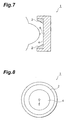
- the light source 2 may be combined into the breast pressing member 1.
- Fig. 7 shows a view of the modified example 1 when viewed from the side of the breast
- Fig. 8 shows another view of the modified example 1 when viewed from the front of the breast.
- Fig. 9 shows a view of the modified example 2 when viewed from the side of the breast
- Fig. 10 shows another view of the modified example 2 when viewed from the front of the breast.
- the above modified examples act in a similar way as those in which the breast pressing member 1 is separated from the light source 2.
- the breast pressing member 1 is not necessarily in a disk shape but may be in an oval shape or in a square shape.
- the material maybe transparent or colored as long as it can pass the light from the light source or breast.
- the reference mark 5 is not necessarily a recess but may be anything that can specify the reference position.
- a desirable shape of the pressing face 4 is a plane or a curved surface, with consideration given to the breast configuration or possible deformation, and an area to which the pressing face 4 is pressed may cover the whole of a breast or a part of a breast, for example, an area covering only a part of the breast around the armpit where breast cancer often develops.
- the light source means may be a light-emitting diode and the image pickup means may be an II (image intensifier).
- This invention can be used in a device for detecting breast cancer tissues in the living body.
Landscapes
- Health & Medical Sciences (AREA)
- Life Sciences & Earth Sciences (AREA)
- Public Health (AREA)
- Molecular Biology (AREA)
- Veterinary Medicine (AREA)
- General Health & Medical Sciences (AREA)
- Pathology (AREA)
- Engineering & Computer Science (AREA)
- Biomedical Technology (AREA)
- Heart & Thoracic Surgery (AREA)
- Medical Informatics (AREA)
- Animal Behavior & Ethology (AREA)
- Surgery (AREA)
- Physics & Mathematics (AREA)
- Biophysics (AREA)
- Gynecology & Obstetrics (AREA)
- Reproductive Health (AREA)
- Nuclear Medicine, Radiotherapy & Molecular Imaging (AREA)
- Oncology (AREA)
- Investigating, Analyzing Materials By Fluorescence Or Luminescence (AREA)
- Investigating Or Analysing Materials By Optical Means (AREA)
- Apparatus For Radiation Diagnosis (AREA)
Abstract
Description
Claims (10)
- A breast cancer detector comprising:wherein breast cancer is detected from the breast image obtained by said image pickup means.a transparent breast pressing member having a pressing face which is pressed to a breast of a subject that makes it possible to observe the breast pressed to the body from the opposite face to said pressing face;a light source means for irradiating light of a designated wavelength at least to a part of the breast in an area to which said pressing face is pressed; andan image pickup means sensitive to light from the breast derived from irradiated light of said light source means and obtaining the breast image through said breast pressing member,
- The breast cancer detector according to Claim 1,
wherein said pressing face of said breast pressing member is provided with a reference mark at which the nipple is placed and said reference mark is superimposed on the breast image obtained by said image pickup means. - The breast cancer detector according to Claim 1,
wherein said light source means is a ring-shaped light source mounted on said pressing face side of said breast pressing member in a manner to surround said pressing face. - The breast cancer detector according to Claim 1,
wherein said light source means is a light source for irradiating light into the transparent member consisting of said breast pressing member, and so structured that light is irradiated from the surface contacting with said pressing face to the breast. - The breast cancer detector according to Claim 1,
wherein said light source means is a light source for irradiating light of a wavelength whose absorption coefficient at breast tissues is different from the absorption coefficient at breast cancer tissues, and said image pickup means is able to image reflected, scattered or diffused light from at least either breast tissues or breast cancer tissues. - The breast cancer detector according to Claim 1,
wherein said light source means is a light source for irradiating light having a wavelength of exciting a fluorescent contrast medium that will make a selective aggregation at breast cancer tissues, and said image pickup means is sensitive to a fluorescent wavelength of said fluorescent contrast medium and so structured to obtain the fluorescent image of the breast of a subject to whom said fluorescent contrast medium is administered. - The breast cancer detector according to Claim 6,
wherein said breast pressing member is provided with a filter that can permit light having a fluorescent wavelength of said fluorescent contrast medium to be transmitted selectively. - The breast cancer detector according to Claim 1,
wherein said light source means is a light source for irradiating light having a wavelength of exciting a fluorescent contrast medium which will aggregate selectively at breast cancer tissues, and said image pickup means is sensitive to a light wavelength which excites said fluorescent contrast medium and so structured to obtain the excitation light image of a breast of a subject to whom said fluorescent contrast medium is administered. - The breast cancer detector according to Claim 8,
wherein said breast pressing member is provided with a filter that selectively blocks the light of fluorescent wavelength of said fluorescent contrast medium. - The breast cancer detector according to Claim 1,
wherein said breast pressing member is provided with the reflecting means that permits light of the wavelength projected from said light source means to reflect selectively from said pressing face to the breast side of a subject.
Applications Claiming Priority (3)
| Application Number | Priority Date | Filing Date | Title |
|---|---|---|---|
| JP2001072510 | 2001-03-14 | ||
| JP2001072510A JP4781548B2 (en) | 2001-03-14 | 2001-03-14 | Breast cancer detection device |
| PCT/JP2002/002370 WO2002078547A1 (en) | 2001-03-14 | 2002-03-13 | Breast carcinoma detector |
Publications (3)
| Publication Number | Publication Date |
|---|---|
| EP1369086A1 true EP1369086A1 (en) | 2003-12-10 |
| EP1369086A4 EP1369086A4 (en) | 2006-09-06 |
| EP1369086B1 EP1369086B1 (en) | 2009-05-06 |
Family
ID=18930080
Family Applications (1)
| Application Number | Title | Priority Date | Filing Date |
|---|---|---|---|
| EP02705140A Expired - Lifetime EP1369086B1 (en) | 2001-03-14 | 2002-03-13 | Breast carcinoma detector |
Country Status (5)
| Country | Link |
|---|---|
| US (1) | US7725170B2 (en) |
| EP (1) | EP1369086B1 (en) |
| JP (1) | JP4781548B2 (en) |
| DE (1) | DE60232228D1 (en) |
| WO (1) | WO2002078547A1 (en) |
Cited By (2)
| Publication number | Priority date | Publication date | Assignee | Title |
|---|---|---|---|---|
| WO2008029354A2 (en) | 2006-09-07 | 2008-03-13 | Koninklijke Philips Electronics N.V. | Optical tomography measurement using an adapted brim for the receiving volume |
| WO2008053411A1 (en) * | 2006-11-02 | 2008-05-08 | Koninklijke Philips Electronics N.V. | Ambient light reduction for optical tomography |
Families Citing this family (4)
| Publication number | Priority date | Publication date | Assignee | Title |
|---|---|---|---|---|
| CN102711595A (en) * | 2010-01-14 | 2012-10-03 | 加利福尼亚大学董事会 | Devices, systems and methods for detecting and reducing or preventing entry of inflammatory mediators into milk ducts |
| JP5848590B2 (en) | 2011-12-02 | 2016-01-27 | 浜松ホトニクス株式会社 | Mammography device |
| JPWO2017047553A1 (en) | 2015-09-18 | 2018-09-27 | 独立行政法人労働者健康安全機構 | Imaging method, imaging apparatus, imaging system, surgery support system, and control program |
| US11882944B1 (en) | 2021-02-12 | 2024-01-30 | Rion Hilliard | Diaper changing device |
Family Cites Families (38)
| Publication number | Priority date | Publication date | Assignee | Title |
|---|---|---|---|---|
| US4212306A (en) * | 1978-05-18 | 1980-07-15 | Khalid Mahmud | Breast examination device and method |
| FI58719C (en) * | 1979-06-01 | 1981-04-10 | Instrumentarium Oy | DIAGNOSTISERINGSANORDNING FOER BROESTKANCER |
| US5139025A (en) * | 1983-10-14 | 1992-08-18 | Somanetics Corporation | Method and apparatus for in vivo optical spectroscopic examination |
| US5555885A (en) * | 1988-12-21 | 1996-09-17 | Non-Invasive Technology, Inc. | Examination of breast tissue using time-resolved spectroscopy |
| US4945239A (en) * | 1989-03-29 | 1990-07-31 | Center For Innovative Technology | Early detection of breast cancer using transillumination |
| JPH032850A (en) * | 1989-05-31 | 1991-01-09 | Pioneer Electron Corp | Fluorescent screen |
| JP2744668B2 (en) * | 1989-11-17 | 1998-04-28 | 三菱電機株式会社 | Optical signal receiver |
| CN1012557B (en) * | 1990-03-17 | 1991-05-08 | 北京海淀龙兴医疗设备科技开发公司 | Detection imaging method of soft tissue and its apparatus |
| JP3217107B2 (en) | 1992-02-14 | 2001-10-09 | 科学技術振興事業団 | Fluorescence tomogram measurement system |
| JP2803443B2 (en) * | 1992-02-24 | 1998-09-24 | 日本電気株式会社 | Surface inspection method and device |
| US6005916A (en) * | 1992-10-14 | 1999-12-21 | Techniscan, Inc. | Apparatus and method for imaging with wavefields using inverse scattering techniques |
| DE4330460C2 (en) * | 1993-09-08 | 1996-05-23 | Siemens Ag | Device for examining tissue with light of different wavelengths |
| DE4340072C2 (en) * | 1993-11-24 | 1996-05-15 | Siemens Ag | Device for examining tissue with light |
| US5730133A (en) * | 1994-05-20 | 1998-03-24 | Dynamics Imaging, Inc. | Optical functional mamoscope |
| DE4445214C2 (en) | 1994-12-17 | 2000-06-29 | Laser & Med Tech Gmbh | Method for determining and reconstructing spatial distributions and intensities of fluorescent dyes and device for carrying out the method |
| US6345194B1 (en) * | 1995-06-06 | 2002-02-05 | Robert S. Nelson | Enhanced high resolution breast imaging device and method utilizing non-ionizing radiation of narrow spectral bandwidth |
| US5692511A (en) * | 1995-06-07 | 1997-12-02 | Grable; Richard J. | Diagnostic tomographic laser imaging apparatus |
| JPH09200304A (en) * | 1996-01-16 | 1997-07-31 | Fuji Xerox Co Ltd | Communication terminal device |
| EP0836409B1 (en) | 1996-04-02 | 2004-03-17 | Koninklijke Philips Electronics N.V. | Localization of an object in a turbid medium using radiation of different wavelenghts |
| JP3896176B2 (en) | 1996-05-21 | 2007-03-22 | 浜松ホトニクス株式会社 | Near-infrared fluorescent tracer and fluorescent imaging method |
| US5713356A (en) * | 1996-10-04 | 1998-02-03 | Optosonics, Inc. | Photoacoustic breast scanner |
| US5825031A (en) * | 1996-10-11 | 1998-10-20 | Board Of Regents The University Of Texas System | Tomographic pet camera with adjustable diameter detector ring |
| US6029077A (en) * | 1996-11-08 | 2000-02-22 | Imaging Diagnostic Systems, Inc. | Device for determining the perimeter of the surface of an object being scanned and for limiting reflection from the object surface |
| US5952664A (en) * | 1997-01-17 | 1999-09-14 | Imaging Diagnostic Systems, Inc. | Laser imaging apparatus using biomedical markers that bind to cancer cells |
| US6091983A (en) * | 1997-02-07 | 2000-07-18 | Alfano; Robert R. | Imaging of objects in turbid media based upon the preservation of polarized luminescence emitted from contrast agents |
| AU6866698A (en) | 1997-03-21 | 1998-10-20 | Dynamics Imaging, Inc. | Dynamic-functional imaging of biological objects using a non-rigid object holder |
| CA2319454C (en) * | 1998-02-11 | 2010-04-27 | Non-Invasive Technology, Inc. | Detection, imaging and characterization of breast tumors |
| US6511579B1 (en) * | 1998-06-12 | 2003-01-28 | Fort James Corporation | Method of making a paper web having a high internal void volume of secondary fibers and a product made by the process |
| US6205353B1 (en) * | 1998-12-22 | 2001-03-20 | Research Foundation Of Cuny | Time-resolved optical backscattering tomographic image reconstruction in scattering turbid media |
| US6254614B1 (en) * | 1999-10-18 | 2001-07-03 | Jerry M. Jesseph | Device and method for improved diagnosis and treatment of cancer |
| US6595933B2 (en) * | 2000-03-31 | 2003-07-22 | Artann Laboratories | Self-palpation device for examination of breast with 3-D positioning system |
| US7103205B2 (en) * | 2000-11-24 | 2006-09-05 | U-Systems, Inc. | Breast cancer screening with ultrasound image overlays |
| US7615008B2 (en) * | 2000-11-24 | 2009-11-10 | U-Systems, Inc. | Processing and displaying breast ultrasound information |
| DE10109539A1 (en) * | 2001-02-28 | 2002-09-12 | Siemens Ag | Device for examining tissue with light |
| US6946841B2 (en) * | 2001-08-17 | 2005-09-20 | Igor Rubashov | Apparatus for combined nuclear imaging and magnetic resonance imaging, and method thereof |
| US20030073930A1 (en) * | 2001-10-17 | 2003-04-17 | Morrissey Gerald R. | Methods and device for preventing or healing injured nipples or areolas in mammalian females or for obtaining samples from nipples in mammalian females |
| US6681130B2 (en) * | 2002-03-14 | 2004-01-20 | Imaging Diagnostic Systems, Inc. | Method for improving the accuracy of data obtained in a laser imaging apparatus |
| EP1551303A4 (en) * | 2002-05-16 | 2009-03-18 | Karmanos B A Cancer Inst | COMBINED DIAGNOSTIC METHOD AND SYSTEM AND ULTRASONIC TREATMENT SYSTEM INCLUDING NON-INVASIVE THERMOMETRY, CONTROL AND AUTOMATION OF ABLATION |
-
2001
- 2001-03-14 JP JP2001072510A patent/JP4781548B2/en not_active Expired - Lifetime
-
2002
- 2002-03-13 EP EP02705140A patent/EP1369086B1/en not_active Expired - Lifetime
- 2002-03-13 US US10/471,015 patent/US7725170B2/en not_active Expired - Fee Related
- 2002-03-13 WO PCT/JP2002/002370 patent/WO2002078547A1/en not_active Ceased
- 2002-03-13 DE DE60232228T patent/DE60232228D1/en not_active Expired - Lifetime
Cited By (4)
| Publication number | Priority date | Publication date | Assignee | Title |
|---|---|---|---|---|
| WO2008029354A2 (en) | 2006-09-07 | 2008-03-13 | Koninklijke Philips Electronics N.V. | Optical tomography measurement using an adapted brim for the receiving volume |
| WO2008029354A3 (en) * | 2006-09-07 | 2008-05-15 | Koninkl Philips Electronics Nv | Optical tomography measurement using an adapted brim for the receiving volume |
| CN101511263B (en) * | 2006-09-07 | 2011-11-23 | 皇家飞利浦电子股份有限公司 | Optical tomography measurement using an adapted brim for the receiving volume |
| WO2008053411A1 (en) * | 2006-11-02 | 2008-05-08 | Koninklijke Philips Electronics N.V. | Ambient light reduction for optical tomography |
Also Published As
| Publication number | Publication date |
|---|---|
| JP4781548B2 (en) | 2011-09-28 |
| DE60232228D1 (en) | 2009-06-18 |
| US20040097810A1 (en) | 2004-05-20 |
| WO2002078547A1 (en) | 2002-10-10 |
| EP1369086A4 (en) | 2006-09-06 |
| US7725170B2 (en) | 2010-05-25 |
| EP1369086B1 (en) | 2009-05-06 |
| JP2002272745A (en) | 2002-09-24 |
Similar Documents
| Publication | Publication Date | Title |
|---|---|---|
| JP5709368B2 (en) | Biological information acquisition device | |
| KR101856909B1 (en) | Apparatus for Measuring Skin Condition with Multiple Lights | |
| US6353753B1 (en) | Optical imaging of deep anatomic structures | |
| US6091983A (en) | Imaging of objects in turbid media based upon the preservation of polarized luminescence emitted from contrast agents | |
| EP1740090B1 (en) | A hair-detection device | |
| CN101541231B (en) | A system for imaging of tissue in an anatomical structure | |
| US10362983B2 (en) | Near infrared photonic prostatoscopy analyzer | |
| WO1984004665A1 (en) | Localization of cancerous tissue by monitoring infrared fluorescence emitted by intravenously injected porphyrin in tumor-specific markers excited by long wavelength light | |
| JP5911196B2 (en) | Photoacoustic imaging device | |
| US20110205651A1 (en) | Aperture stop | |
| CN102429644B (en) | Vascular image positioning device | |
| EP1167951A1 (en) | Fluorescent image obtaining apparatus | |
| JP2007525261A (en) | A microscale compact device for in vivo medical diagnostics combining optical imaging and point fluorescence spectroscopy | |
| JPH10201707A5 (en) | ||
| JP2003516795A (en) | Method and apparatus for measuring local distribution of measurement parameters | |
| US11050951B2 (en) | Guidance system for a near-infrared fluorescein angiography operation with a 785nm continuous wavelength light source | |
| CN105962891B (en) | A kind of contact excitation light source of fluorescence imaging detecting system | |
| KR20230153430A (en) | Dental imaging systems and image analysis | |
| US20210127957A1 (en) | Apparatus for intraoperative identification and viability assessment of tissue and method using the same | |
| CN102026582A (en) | Data collection method | |
| US7725170B2 (en) | Breast carcinoma detector | |
| CN114965434A (en) | Raman deep penetration imaging system based on safe laser irradiation dosage | |
| WO2005048826A1 (en) | Lymph node detector | |
| KR101710902B1 (en) | An astral lamp and astral lamp system about projection for near infrared fluoresence diagnosis | |
| JP2008521453A (en) | End scope |
Legal Events
| Date | Code | Title | Description |
|---|---|---|---|
| PUAI | Public reference made under article 153(3) epc to a published international application that has entered the european phase |
Free format text: ORIGINAL CODE: 0009012 |
|
| 17P | Request for examination filed |
Effective date: 20030908 |
|
| AK | Designated contracting states |
Kind code of ref document: A1 Designated state(s): AT BE CH CY DE DK ES FI FR GB GR IE IT LI LU MC NL PT SE TR |
|
| AX | Request for extension of the european patent |
Extension state: AL LT LV MK RO SI |
|
| A4 | Supplementary search report drawn up and despatched |
Effective date: 20060804 |
|
| 17Q | First examination report despatched |
Effective date: 20070420 |
|
| GRAP | Despatch of communication of intention to grant a patent |
Free format text: ORIGINAL CODE: EPIDOSNIGR1 |
|
| GRAP | Despatch of communication of intention to grant a patent |
Free format text: ORIGINAL CODE: EPIDOSNIGR1 |
|
| GRAS | Grant fee paid |
Free format text: ORIGINAL CODE: EPIDOSNIGR3 |
|
| GRAA | (expected) grant |
Free format text: ORIGINAL CODE: 0009210 |
|
| AK | Designated contracting states |
Kind code of ref document: B1 Designated state(s): DE FR GB |
|
| REG | Reference to a national code |
Ref country code: GB Ref legal event code: FG4D |
|
| REF | Corresponds to: |
Ref document number: 60232228 Country of ref document: DE Date of ref document: 20090618 Kind code of ref document: P |
|
| PLBE | No opposition filed within time limit |
Free format text: ORIGINAL CODE: 0009261 |
|
| STAA | Information on the status of an ep patent application or granted ep patent |
Free format text: STATUS: NO OPPOSITION FILED WITHIN TIME LIMIT |
|
| 26N | No opposition filed |
Effective date: 20100209 |
|
| PGFP | Annual fee paid to national office [announced via postgrant information from national office to epo] |
Ref country code: FR Payment date: 20140311 Year of fee payment: 13 |
|
| PGFP | Annual fee paid to national office [announced via postgrant information from national office to epo] |
Ref country code: GB Payment date: 20140312 Year of fee payment: 13 |
|
| PGFP | Annual fee paid to national office [announced via postgrant information from national office to epo] |
Ref country code: DE Payment date: 20140417 Year of fee payment: 13 |
|
| REG | Reference to a national code |
Ref country code: DE Ref legal event code: R119 Ref document number: 60232228 Country of ref document: DE |
|
| GBPC | Gb: european patent ceased through non-payment of renewal fee |
Effective date: 20150313 |
|
| REG | Reference to a national code |
Ref country code: FR Ref legal event code: ST Effective date: 20151130 |
|
| PG25 | Lapsed in a contracting state [announced via postgrant information from national office to epo] |
Ref country code: DE Free format text: LAPSE BECAUSE OF NON-PAYMENT OF DUE FEES Effective date: 20151001 Ref country code: GB Free format text: LAPSE BECAUSE OF NON-PAYMENT OF DUE FEES Effective date: 20150313 |
|
| PG25 | Lapsed in a contracting state [announced via postgrant information from national office to epo] |
Ref country code: FR Free format text: LAPSE BECAUSE OF NON-PAYMENT OF DUE FEES Effective date: 20150331 |