EP1367744A2 - Automatic dispersion compensation device and compensation method - Google Patents
Automatic dispersion compensation device and compensation method Download PDFInfo
- Publication number
- EP1367744A2 EP1367744A2 EP03011116A EP03011116A EP1367744A2 EP 1367744 A2 EP1367744 A2 EP 1367744A2 EP 03011116 A EP03011116 A EP 03011116A EP 03011116 A EP03011116 A EP 03011116A EP 1367744 A2 EP1367744 A2 EP 1367744A2
- Authority
- EP
- European Patent Office
- Prior art keywords
- dispersion
- chromatic dispersion
- transmission quality
- channels
- amount
- Prior art date
- Legal status (The legal status is an assumption and is not a legal conclusion. Google has not performed a legal analysis and makes no representation as to the accuracy of the status listed.)
- Withdrawn
Links
Images



















Classifications
-
- H—ELECTRICITY
- H04—ELECTRIC COMMUNICATION TECHNIQUE
- H04B—TRANSMISSION
- H04B10/00—Transmission systems employing electromagnetic waves other than radio-waves, e.g. infrared, visible or ultraviolet light, or employing corpuscular radiation, e.g. quantum communication
- H04B10/25—Arrangements specific to fibre transmission
- H04B10/2507—Arrangements specific to fibre transmission for the reduction or elimination of distortion or dispersion
- H04B10/2513—Arrangements specific to fibre transmission for the reduction or elimination of distortion or dispersion due to chromatic dispersion
- H04B10/25133—Arrangements specific to fibre transmission for the reduction or elimination of distortion or dispersion due to chromatic dispersion including a lumped electrical or optical dispersion compensator
-
- H—ELECTRICITY
- H04—ELECTRIC COMMUNICATION TECHNIQUE
- H04B—TRANSMISSION
- H04B10/00—Transmission systems employing electromagnetic waves other than radio-waves, e.g. infrared, visible or ultraviolet light, or employing corpuscular radiation, e.g. quantum communication
- H04B10/25—Arrangements specific to fibre transmission
- H04B10/2507—Arrangements specific to fibre transmission for the reduction or elimination of distortion or dispersion
- H04B10/2572—Arrangements specific to fibre transmission for the reduction or elimination of distortion or dispersion due to forms of polarisation-dependent distortion other than PMD
Definitions
- the present invention relates to an optical communication system, and more specifically, it relates to a chromatic dispersion compensation technology as an indispensable technology for realizing an ever-progressing large-capacity, high-speed and long-haul optical communication system.
- it relates to an automatic dispersion compensation device optimally compensating for chromatic dispersion and polarization-mode dispersion in a transmission line and a compensation method thereof.
- WDM wavelength division multiplexing
- a tolerance for chromatic dispersion is remarkably small.
- the chromatic dispersion tolerance of a 40Gb/s non-return -to-zero (NRZ) system is 100ps/nm (pico-sec/nm) or less.
- the repeater spacing of an optical communication system is not constant. For this reason, if, for example, 1. 3 ⁇ m zero-dispersion single mode fiber (SMF) with a chromatic dispersion value of 17ps/nm/km is used, chromatic dispersion deviates from its tolerance threshold when repeaters are apart by only several kilo-meters.
- SMF zero-dispersion single mode fiber
- chromatic dispersion tolerance threshold of a 40Gb/s NRZ signal.
- an automatic wavelength compensation system always monitoring the chromatic dispersion value in a transmission line and optimally controlling the amount of wavelength compensation, is indispensable not only in an SMF transmission line but also in a system using a 1.55 ⁇ m zero-dispersion shift fiber (DSF) or an NZ (non-zero)-DSF for a transmission line.
- DSF zero-dispersion shift fiber
- NZ non-zero
- PMD is dispersion due to the respective different propagation delay times of the polarization elements (two pieces of mode light: for example, a TE mode light and TM mode light) of an optical signal, and it can occur in all types of optical fibers.
- an optical fiber constituting an old optical transmission line mainly laid in countries other than Japan, has a large PMD value exceeding 1ps/km 1/2 (pico-sec/ km 1/2 : one pico is 10 -12 ) per unit length.
- an optical delay difference ( ⁇ ) for one time slot of 25ps of a 40Gb/s NRZ signal is 7ps or more.
- polarization-mode dispersion is also not negligible as in the case of chromatic dispersion described above.
- components causing polarization-mode dispersion such as an optical amplifier, a chromatic dispersion compensator and the like, must be installed in the transmission line of an optical communication system, there is a possibility that the transmission distance of an optical signal will be further limited.
- polarization-mode dispersion varies depending on stress or temperature change that are placed on an optical fiber as time elapses, the state of polarization-mode dispersion must be monitored and be dynamically compensated for not only at the time of the construction of a system but also during the operation.
- chromatic dispersion and polarization-mode dispersion are major factors for limiting the performance of an optical communication system.
- an automatic dispersion compensation system individually and dynamically compensating for both chromatic dispersion and polarization-mode dispersion must be provided.
- a method for measuring polarization-mode dispersion using Jones' vector and a device thereof are proposed in Japanese Patent Laid-open No. 9-72827 as one example.
- a polarization dispersion monitor monitoring a specific frequency element of an incoming signal is also proposed although it is difficult to apply it in an environment where there is chromatic dispersion.
- Any practical chromatic dispersion monitor directly or indirectly uses waveform distortion due to dispersion.
- waveform distortion due to these two forms of dispersion cannot be distinguished. Therefore, it is difficult to realize an automatic dispersion compensator simultaneously compensating for both chromatic dispersion and polarization-mode dispersion.
- Fig. 1 shows the entire configuration of a conventional optical communication system used to describe the problems.
- a multiplexer 101 multiplexes the outputs of a transmitter TX100, for each channel (100GHz interval between channels) from channel 1 (196THz) to channel 40 (192.1THz), and transmits it to a receiver through a transmission line of, for example, 90km. It is assumed that dispersion in the transmission line is 5.Ops/nm/km for channel 1 and the dispersion slope is 0.06ps/nm 2 /km.
- a demultiplexer 103 demultiplexes signals for each channel, and a variable chromatic dispersion compensator (VDC) 104 compensates for the chromatic dispersion of signals in each channel. Then, the VDC 104 transmits these signals to a receiver RX105. Then, a monitor/controller 106 monitors the transmission quality of the received result and controls the VDC 104.
- VDC variable chromatic dispersion compensator
- Fig. 2 shows the relation between the average number of errors per second and the residual amount of chromatic dispersion obtained when the decision threshold and decision phase of the receiver is optimized. If the allowable number of, penalties of error due to chromatic dispersion is 1, dispersion tolerance is approximately 98ps/nm.
- Fig. 3 shows the relation between the number of errors and the residual amount of chromatic dispersion of the decision threshold in which there are errors with the allowable number of errors equal to 1.
- the present invention is an automatic dispersion compensation device with a variable chromatic dispersion compensator applied to optical signals input from an optical transmitter transmitting the optical signals from a plurality of channels, through a transmission line.
- the automatic dispersion compensation device comprises a transmission quality measurement unit measuring the transmission quality of the optical incoming signals for each of the plurality of channels; and a chromatic dispersion compensation amount control unit for separating and detecting transmission quality degradation, due to chromatic dispersion in the transmission line, in the measurement result of the transmission quality measurement unit from degradation due to other factors and controlling the variable chromatic dispersion compensator in such a way as to compensate for the degradation.
- optimal control of chromatic dispersion in a transmission line can be exercised in order to influence communication quality using a general-purpose transmission quality monitor instead of a special dispersion monitor, and system performance can thus be improved.
- Fig. 4 shows the basic configuration of the automatic dispersion compensation device of the present invention.
- Fig. 4 shows the automatic dispersion compensation device with a variable chromatic dispersion compensator applied to optical signals input from an optical transmitter transmitting optical signals from one or more channels, through a transmission line.
- an automatic dispersion compensation device 1 comprises a transmission quality measurement unit 2 and a chromatic dispersion compensation amount control unit.
- the transmission quality measurement unit 2 measures the transmission quality of optical signals from one or more channels.
- the transmission quality measurement unit 2 is a transmission quality monitor measuring, for example, the 0 value, that is, the error rate of an incoming signal, and the like.
- the a chromatic dispersion compensation amount control unit 3 separates and detects, from the measurement result of the transmission quality measurement unit 2, transmission quality degradation due to chromatic dispersion in a transmission line and due to factors other than the chromatic dispersion, and controls the variable chromatic dispersion, compensator 5 in such a way as to compensate for the degradation.
- the automatic dispersion compensation device 1 further comprises a residual chromatic dispersion amount increase/decrease unit for increasing/decreasing the difference in the magnitude of dispersion compensation between channel, for any residual amount of chromatic dispersion obtained as a result of compensation by the variable chromatic dispersion compensator 5, depending on the wavelength of an optical signal; and a chromatic dispersion amount increase/decrease judgment unit for comparing the measurement result of transmission quality after compensation by the variable chromatic dispersion compensator and the residual chromatic dispersion amount increase/decrease unit, between channels, and judging whether the amount of chromatic dispersion in the transmission line increases or decreases.
- a residual chromatic dispersion amount increase/decrease unit for increasing/decreasing the difference in the magnitude of dispersion compensation between channel, for any residual amount of chromatic dispersion obtained as a result of compensation by the variable chromatic dispersion compensator 5, depending on the wavelength of an optical signal
- the residual chromatic dispersion amount increase/decrease unit can increase/decrease the amount of chromatic dispersion compensation for the difference between channels across the entire channel range in such a way as to change it in the form of a slope or step, as chromatic dispersion increases.
- the residual chromatic dispersion amount increase/decrease unit can increase/decrease the amount of chromatic dispersion compensation in a specific channel range in such a way as to change it in the form of a slope or step.
- the automatic dispersion compensation device 1 further comprises a receiver state detection unit detecting the state, such as the voltage and temperature, of each receiver unit receiving optical signals through a transmission line.
- the chromatic dispersion compensation control unit 3 can also stop/prevent control by the variable chromatic dispersion compensator in accordance with the detection result of the receiver state detection unit and the measurement result of the transmission quality measurement unit 2.
- the automatic dispersion compensation device 1 further comprises a plurality of polarization-mode dispersion compensators for signals from each channel input of a transmission line, and a plurality of monitors detecting polarization-mode dispersion after compensation by a polarization-mode dispersion compensator in addition to the variable chromatic dispersion compensator.
- the chromatic dispersion compensation control unit 3 can also control the variable chromatic dispersion compensator and polarization-mode dispersion compensator in accordance with the timewise change tendency of the measurement result of the transmission quality measurement unit and the detection result of the monitor.
- the transmission quality of incoming optical signals for one or more channels is measured, where from the measurement result transmission quality degradation, due to chromatic dispersion in a transmission line, is detected and separated from that due to factors other than the chromatic dispersion, and the variable chromatic dispersion compensator is controlled in such a way as to compensate for the degradation.
- a program for enabling the computer to perform a step of receiving the transmission quality measurement result of the optical signals for each of a plurality of channels, the step of detecting and separating, from the transmission quality measurement result, the transmission quality degradation due to chromatic dispersion in a transmission line and due to other factors and the step of controlling variable chromatic dispersion compensation in such a way as to compensate for the degradation is used.
- chromatic dispersion change in a transmission line can be compensated for using a general-purpose transmission quality monitor with an existing function instead of a special dispersion monitor.
- Fig. 5 shows the basic chromatic dispersion compensation method of the present invention.
- optical signals are transmitted from a transmitting transmitter 10 to a receiver 12 through a transmission line 11.
- a chromatic dispersion compensator is installed before a receiver 12 and chromatic dispersion compensation is carried out there.
- the wavelength of the signal and the amount of chromatic dispersion of a 100km single mode fiber (SMF) are 1,550nm and 17ps/nm/km, respectively
- the chromatic dispersion in the transmission line can be compensated for by the dispersion compensator 13 supplying an amount of dispersion of -1,700ps/nm.
- chromatic dispersion is compensated for using a general-purpose transmission quality monitor instead of a special dispersion monitor.
- a general-purpose transmission quality monitor instead of a special dispersion monitor.
- an error rate or a Q value is used for transmission quality.
- Such a transmission quality monitor is described below with reference to Figs. 6 and 7.
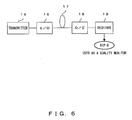
- Fig. 6 shows the case where in a SONET/SDH (synchronous optical network/synchronous digital hierarchy) system, an 8-bit value, called a B1 byte, is used to store information about operation /maintenance overhead.
- SONET/SDH synchronous optical network/synchronous digital hierarchy
- signals from a transmitter 15 are converted into optical signals by an electrical/optical converter (E/O) 16 and are transmitted to a receiver, through a transmission line 17.
- the optical signals are converted into electrical signals by an optical/electrical converter (O/E) 18 and are supplied to the receiver 19.
- the B1 byte is used to monitor code errors between regenerator adopting a monitoring method, called BIP-8 (bit interleaved parity 8), or between an intermediate regenerator and the multiplex regenerator. This can be used by a quality monitor to indicate the quality of transmission signals in the relevant section.
- BIP-24 ⁇ N Between terminal stations multiplex regenerator adopting a monitoring method, called BIP-24 ⁇ N, a B2 byte used to monitor code errors can also be used as a byte indicating transmission quality, and all information can be divided and monitored into a plurality of 24 bits . Therefore, in this case, more detailed error information can be extracted compared with BIP-8.
- Fig. 7 shows the case where transmission quality is monitored using an error correction code, that is, by forward error correction (FEC).
- FEC forward error correction
- a transmitter 15 comprises a signal source 20 and an FEC encoder 21, and a receiver comprises an FEC decoder 23 as an error correction unit 19 inside the receiver, and a performance monitor 24 calculating the number of error corrections and the like.
- error information is supplied to a control firmware 25 and a control signal for a variable dispersion compensator 22 in the receiver is output.
- a general configuration used for code error monitoring and correction in the receiver can be used without modification, instead of a special chromatic dispersion monitor.
- Fig. 8 shows an example configuration of the optical communication system in the first preferred embodiment of the present invention (No. 1).
- a dispersion compensator is controlled using the monitoring result of a transmission quality monitor.
- the outputs of transmitters (TX1 through TXN) 30 for each channel are multiplexed by a multiplexer 31 and are transmitted to a receiver through a transmission line 32.
- incoming signals RX1, RX2, ..., RXN for each channel are demultiplexed by a demultiplexer 33.
- the dispersion in the transmission line 32 and the like of signals for each channel is compensated for by a dispersion compensator 34, signals for each channel are converted into electrical signals by an optical/electrical conversion unit 35, and are amplified by an amplifier 36 and are output by a clock extraction circuit 37 and a decision circuit 38, as incoming signals.
- a transmission quality monitor 39 monitors the transmission quality of incoming signals for each channel, and a dispersion compensator 34 for each channel is controlled by a control circuit 40, based on the mentioned result.
- Fig. 9 shows an example configuration of the optical communication system in the first preferred embodiment (No. 2).
- a transmission quality monitor 39 monitors the transmission quality of any channel, for example, incoming signals as the output of the identification circuit of one channel, and a control circuit 40 controls a dispersion compensator 34 that is commonly provided for all channels, between a transmission line 32 and a demultiplexer 33, unlike that shown in Fig. 8.
- Fig. 9 only one dispersion compensator 34 is provided immediately after the transmission line 32, and chromatic dispersion is collectively compensated for. Since transmission quality degradation due to chromatic dispersion change in a transmission line basically does not depend on a wavelength, that is, a channel, and that almost the same amount of degradation occurs in any channel, which is described later, such a collective compensation is possible. Compared with the individual compensation method for each channel shown in Fig. 8, although such a collective compensation method has great advantages in cost and device size, sometimes it is difficult to make such collective compensation.
- VDC variable chromatic dispersion compensator
- the second reason is that if a transmission distance is long, it becomes difficult to make collective compensation.
- the wavelength dependence of chromatic dispersion is called a chromatic dispersion slope. Since an optical fiber has such a dispersion slope in its nature, the slope must also be compensated for, if a transmission distance is long. Accordingly, it is difficult to make collective compensation.
- Fig. 10 shows an example configuration of the optical communication system in the first preferred embodiment (No. 3).
- one control circuit 40 controls all dispersion compensators provided for each channel using all the outputs of the transmission quality monitors provided for each channel in a receiver, unlike the other configurations.
- Fig. 11 shows an example configuration of the optical communication system in the first preferred embodiment (No. 4).
- one control circuit 40 controls one dispersion compensator commonly provided for each channel using all the monitoring results of transmission quality monitors provided for each channel in a receiver, unlike the other configurations.
- Fig. 12 is a flowchart showing the dispersion compensation control process in the configuration shown in Fig. 10.
- a channel number is set to 1
- step S2 a process for setting an optimal dispersion compensation is applied to it. This process has been already described with reference to Fig. 5.
- the amount of chromatic dispersion in a transmission line varies depending on the characteristic and length of a fiber, the used wavelength and the like. Furthermore, an optical land communication system does not have uniform span configuration. In particular, in an ultra-high-speed optical communication system with a small wavelength tolerance, the amount of chromatic dispersion compensation must be optimized for each chromatic dispersion compensator. Step S2 indicates such a process of each chromatic dispersion compensator.
- the amount of chromatic dispersion of a fiber specified in its manual can be used.
- testing and changing the amount of compensation can also determine it.
- step S3 it is judged whether the channel number is N, that is, if it is the last channel. If it is not the last channel, then by step S4 the channel number is incremented and the processes in and after step 2 are repeated. Then, when it reaches N, the flow proceeds to the process in step S5.
- steps S1 through S4 are, for example, performed at the time of the initial setting of the system.
- step S5 a channel number is set to 1, and in step S6, the transmission quality of the channel is measured. Then, in step S7, it is judged whether the channel number is the last N. If it is not N, then by step S8, the channel number is incremented and the processes in steps S6 and S7 are repeated.
- step S9 it is judged whether there is transmission quality degradation in any of the channels . If there is no degradation, the processes in and after step S5 are repeated. If there is degradation even in one channel, then by step S10 it is further judged whether there is dependence between channels.
- This dependence between channels is the amount of transmission quality degradation and means, for example, that the numbers of errors for each channel is almost the same.
- the amount of chromatic dispersion in a transmission line changes, for example, as temperature changes, which is described later.
- the amount of change due to temperature has no relation to its wavelength, and generally the distribution of dispersion change is the same throughout all of the channels. Therefore, transmission quality degradation has dependence on the amount of distribution of dispersion change between channels (there is almost the same degradation in all the channels).
- step S10 it is judged that there is no such dependence between channels, it is judged that the transmission quality degradation is not due to chromatic dispersion in a transmission line, and the processes in and after step S5 are repeated without compensating for the degradation, which is the subject matter of the present invention.
- step S10 If in step S10 it is judged that there is such dependence between channels, the degradation is compensated for. Firstly, in step S11, the channel number is set to 1, and in step S12, the amount of dispersion is optimized, that is, the degradation is compensated for. Then, in step S13, it is judged whether the channel number is the last N. If it is not N, then by step S14, the channel number is incremented, and the processes in steps S12 and S13 are repeated. If in step S13 it is N, one cycle of the process terminates.
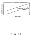
- Fig. 13 shows the change of transmission line dispersion due to this temperature change. As shown in Fig. 13, the amount of chromatic dispersion almost uniformly changes across the entire wavelength range as temperature changes. For this reason, transmission quality degradation due to the change in the amount of wavelength dispersion in a transmission line does not occur individually in each channel and occurs in all channels with the same tendency.
- Figs. 14 and 15 show the simulation results on the change of the average number of errors per second that is caused by the change of transmission line dispersion. Firstly, at the time of the initial setting of the system operation, the remaining amount of dispersion of each channel is set in such a way that transmission quality becomes the best. This setting amount is the optimal amount of dispersion.
- Fig. 14 shows the change of the average number of errors caused when the residual amount of dispersion increases by ⁇ due to factors, such as temperature change and the like, and it is found that the transmission quality of all channels simultaneously degrade. In this case, if the residual amount of dispersion is improved by 1, specifically, is brought close to the optimal value, the respective transmission qualities of all channels are all simultaneously improved.
- Fig. 15 shows the case where the residual amount of dispersion increases by ⁇ and the number of errors in a state where the residual amount of dispersion is improved by 1. In this case, it is found that there is the same tendency as in Fig. 14.
- transmission quality degradation due to factors other than the change of the amount of chromatic dispersion, such as the change of the identification threshold and identification phase of a receiver, the wavelength change of a transmitting light source, or the degradation and failure of components and materials, occurs individually in each channel of a chromatic dispersion compensator at control time intervals, such as in units of minutes. Therefore, the factors of transmission quality degradation can be separated.
- the respective transmission quality of a plurality of channels can be monitored and a chromatic dispersion compensator can be provided for each channel, regardless of the existence /non-existence of the dependence between channels of a transmission quality change characteristic.
- a chromatic dispersion compensator can be provided for each channel, regardless of the existence /non-existence of the dependence between channels of a transmission quality change characteristic.
- the chromatic dispersion compensators jointly operate, transmission quality degradation due to factors other than chromatic dispersion can also be handled, and the problem, such as no control, can also be prevented from occurring.
- Fig. 16 shows an example configuration of an optical communication system in the second preferred embodiment (No.1).
- the configuration shown in Fig. 16 is similar to that of the first preferred embodiment (No. 3) shown in Fig. 10.
- one, corresponding to channel 1 of the chromatic dispersion compensators 34 for each channel compensates for dispersion by adding ⁇ 1 to the optimal amount from the control circuit 40 that is obtained in step S12 of Fig. 12.
- a chromatic dispersion compensator corresponding to channel 2 compensates for dispersion by adding ⁇ 2 to the optimal amount.
- each dispersion compensator for each channel generally compensates for dispersion by adding a different amount to the optimal value.
- This amount ⁇ n of chromatic dispersion is used, when dispersion is compensated for, and which is added to the optimal value can be determined, for example, by giving a different slope to the amount of dispersion depending on a channel number or changing it in the form of a step.
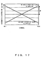
- Fig. 17 shows the case where the additional amount is determined by giving either positive or negative slope to the amount of dispersion in accordance with the increase of a channel number. If either positive or negative slope is given in this way, for example, the maximum amount of the residual dispersion must have minimal influence on transmission quality and be suppressed to the number of errors allowable by the chromatic dispersion compensator, in other words, must be suppressed within the range of the allowable penalty.
- the residual amount of dispersion in order to determine the influence on transmission quality, the residual amount of dispersion must be compared with the amount of chromatic dispersion tolerance. For example, if a 40Gbit/s NRZ signal is used, the chromatic dispersion tolerance is 60 to 1OOps/n In this case, the amount of dD shown in Fig. 17 must be reduced compared with this amount. Since the amount of chromatic dispersion tolerance varies depending on the characteristic of a receiver/transmitter and the amount of penalty allowable by the chromatic dispersion compensator, it must be checked for each system.
- the minimum additional amount of chromatic dispersion is influenced by the sensitivity of a chromatic dispersion monitor or transmission quality monitor.
- a transmission quality monitor is sensitive enough to detect the influence of a 1 ps/nm chromatic dispersion change, it is sufficient if the amount of dD is 1 ps/nm or more.
- the detection sensitivity of a transmission quality monitor is 100 ps/nm, the sensitivity is not negligible compared with the chromatic dispersion tolerance, and the system is broken.
- the result was that it is practically possible for a transmission quality monitor to have a sensitivity of approximately 1 ps/nm.
- Fig. 18 shows an example configuration of an optical communication system in the second preferred embodiment (No. 2).
- a dispersion compensator for each channel compensates for dispersion by adding a different additional amount to the optimal amount for each channel.
- one dispersion compensator 34 simultaneously compensates for all channels.
- a dispersion slope provider 50 which is designed to give a slope to the residual amount of dispersion for a channel, that is, a wavelength, gives a slope equivalent to an addition for each channel, to the result of the compensation, as shown in Fig. 17, and inputs the result to the demultiplexer 33.
- the order of the dispersion compensator 34 and dispersion slope provider 50 can also be reversed.
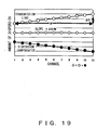
- This dispersion slope compensation is described below with reference to Fig. 19.
- white points indicate the chromatic dispersion characteristic.
- a dispersion compensator compensates for chromatic dispersion in such a way as to obtain the amount of dispersion that does not depend on a channel indicated by diamonds, by providing the amount of chromatic dispersion compensation indicated by black points.
- a method for determining the value of a black point corresponding to a white point for each channel and providing the dispersion compensator with this value corresponds to the designation of an individual addition described with reference to Fig. 16.
- compensation is conducted for all channels by providing a specific channel with the value of each white point and that of its slope. Since the value of this slope does not depend on temperature and the like, the value of the slope can be set based on the value of a transmission line if the dispersion slope information of the transmission line is known in advance.
- Fig. 20 shows an example configuration of the optical communication system in the second preferred embodiment (No. 3) .
- the dispersion slope provider 50 gives dispersion with a specific slope to the result of compensation by the dispersion compensator 34, in Fig. 20, further changing the dispersion slope using a variable dispersion slope compensator 51 compensates for chromatic dispersion.
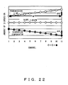
- Figs. 21 and 22 show how to optimize such a dispersion slope when the dispersion slope changes in this way.
- Fig. 21 shows the first optimization method. In this case, firstly, at the time of initial setting of the system, the amount of chromatic dispersion compensation is optimized using a transmission quality monitor corresponding to one channel, and then, the dispersion slope is optimized using transmission quality monitors corresponding to one or more channels. In this example, the amount of chromatic dispersion compensation is optimized for channel 1, and then, the slope is optimized.
- Fig. 22 shows the second optimization method.
- the amounts of chromatic dispersion compensation of a plurality of channels are optimized.
- the dispersion slopes of channel 1 and 11 are optimized using W and ⁇ D shown in Fig. 22.
- the amount of dispersion equivalent to ⁇ n for each channel is given.
- Fig. 23 shows an example configuration of the optical communication system used in the simulation. Although this is basically the same as the optical communication system described with reference to Fig. 1, it differs from the system shown in Fig. 1 in that the additional amount of dispersion, with the slope shown in Fig. 24, is used for chromatic dispersion compensation for each channel.
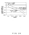
- Figs. 25 and 26 show the results of the simulations. If the average number of errors, 1 per second, is used as the allowable number for transmission quality degradation, that is, the penalty, then in Fig. 25, the number of errors does not exceed the allowable number in any channel before the amount of the chromatic dispersion increase in a transmission line reaches ⁇ ps/nm. However, when it reaches ⁇ +1 ps/nm, the number of errors exceeds the allowable value due to the slope of the additional amount of the chromatic dispersion from the side of channel 40 to which an amount of +2 ps/nm is added.
- Fig. 26 shows the case where the amount of chromatic dispersion in a transmission line decreases.
- the number of errors does not exceed the allowable value in any channel up to an amount of decrease of - ⁇ ps/nm, when it reaches - ⁇ -1 ps/nm, the number of errors exceeds the allowable value from the side of channel 1 to which the an amount of -2 ps/nm is added, in accordance with its slope.
- chromatic dispersion is compensated for by differentiating the optimal amount of chromatic dispersion of each channel, specifically, adding a different amount to the optimal amount of chromatic dispersion for each channel and where such a different amount is set for part of the channels in a form of a slope or step, is described with reference to Figs. 27 to 37.
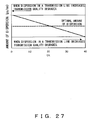
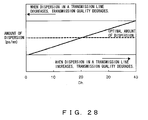
- Figs. 27 through 29 show the case where the additional amount of chromatic dispersion is set for all of the channels in the form of a slope.
- transmission quality degrades from the channel 1 side
- Fig. 28 conversely, it degrades from the channel 40 side.
- the transmission quality of channel 20 located at the center degrades firstly.
- Figs. 30 through 33 show the case where the additional amount of chromatic dispersion is set for all of the channels in the form of a step. In Figs. 30 through 33, the same additional amount of chromatic dispersion is set for a plurality of channels.
- Figs. 34 and 35 show the case where an additional amount of chromatic dispersion is set in part of the channels used in an optical communication system in the form of a slope.
- the amount of chromatic dispersion in a transmission line increases, firstly, transmission quality degrades in the neighborhood of channel 20 located at the center. If the chromatic dispersion in a transmission line decreases, firstly, transmission quality degrades in the neighborhood of channels 30 and 10 in Figs. 34 and 35, respectively.
- Figs 36 and 37 show the case where an additional amount of chromatic dispersion is set in part of the channels used in an optical communication system in the form of a step. In each of Figs. 36 and 37, whether the chromatic dispersion in a transmission line increases or decreases can be judged by the transmission quality of that channel which firstly degrades.
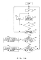
- Fig. 38 is a flowchart showing the process of judging whether the amount of chromatic dispersion in a transmission line increases or decreases in the second preferred embodiment.
- channel number n is set to 1
- step S22 the transmission quality information for the channel is obtained.
- step S23 it is judged whether n is less than the maximum number of channel N. If it is less than N, then in step S24, n is incremented, and the processes in and after step S21 are repeated.
- step S32 if is not judged that n is less than N, in step S25 it is judged whose channel transmission quality changes. If there is no change, the processes in step 21 and after are repeated.
- step S26 it is judged whether the change occurs on the side of channel 1. If it occurs on the side of channel 1, then in step S27 it is judged that the amount of transmission dispersion in a transmission line has decreased. If it does not occur on the side of channel 1, then in step S28, it is judged whether the transmission quality change occurs on the side of channel N. If it occurs on the side of channel N, then by step S29 it is judged that the amount of transmission dispersion in a transmission line has increased. If it too does not occur on the side of channel N, the processes in and after step S21 are repeated. These judgment results correspond to those made when a positive slope is applied to the residual amount of dispersion in Fig. 17.
- the third preferred embodiment of the present invention is described.
- the state of each components of the optical communication system is monitored. If there is a characteristic change factor for each component, such as the voltage change of a power supply and the like, it is judged that there is no dependence between channels in the transmission quality change, regardless of whether the result of a transmission quality monitor judges that transmission quality degrades. In this case, control is exercised in such a way that a dispersion compensator does not compensate for the chromatic dispersion.
- Fig. 39 shows an example configuration of the optical communication system in the third preferred embodiment (No. 1).
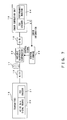
- This optical communication system comprises state monitors 55 monitoring the state of each transmitter 30, a state monitor 56 monitoring the multiplexer 31, state monitors 57 and 59 monitoring the transmission lines 32, a state monitor 58 monitoring the repeater 54, a state monitor 60 monitoring the demultiplexer 33, state monitors 61 monitoring the optical/electrical conversion units 35, amplifiers 36, clock extraction circuits 37, state monitors 62 monitoring decision circuits 38 and the like.
- the output of each state monitor is supplied to the control circuit 40 and each dispersion compensator 34 is controlled.
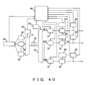
- Fig. 40 shows an example configuration of the optical communication system in the third preferred embodiment (No. 2). Since in Fig. 40, temperature and power supply voltage have great influence on the characteristic of each component of the optical communication system, the optical communication system further comprises monitors monitoring temperature and power supply voltage, and monitors monitoring only temperature. Specifically, the optical communication system further comprises temperature/power supply voltage change monitors 64 monitoring the transmitters 30 and optical/electrical conversion units (O/E) 35 and temperature monitors 65 monitoring the multiplexer 31 and demultiplexer 33. The result of each monitor is supplied to the control circuit 40.
- O/E optical/electrical conversion units
- Fig. 41 is a flowchart showing the chromatic dispersion control process in the third preferred embodiment.
- step S31 n indicating a channel number
- step S32 it is judged whether there is any characteristic change in the TX1, that is, the first transmitter. If there is no characteristic change in the TX1, then in step S33, it is judged whether there is any characteristic change in the O/E, that is, optical/electrical conversion unit 35. If there is no characteristic change in the O/E, then in step S35 it is judged that there is no characteristic change in the multiplexer 31. If there is no characteristic change in the multiplexer 31, then in step S35 it is judged whether there is no characteristic change in the demultiplexer 33.
- step S36 the transmission quality is measured, and the flow proceeds to a process in step S37. If in each of steps S32, S33, S34 and S35, it is judged that there is a characteristic change, the flow immediately proceeds to the process in step S37.
- step S37 it is judged whether n is the last channel number, specifically whether the process reaches the last channel. If it has not yet reached the last channel, then in step S38 the channel number is incremented, and processes in and after step S32 are repeated.
- step S39 it is judged whether there is any dependence between channels in the transmission quality change. If there is no dependence between channels, there is no need to control the dispersion compensator, and the processes in and after step S31 are repeated. If it is judged that there is dependence between channels, in step S40 the dispersion compensator 34 is controlled and then, the processes in and after step S31 are repeated.
- Fig. 42 shows an example configuration of the receiver of the optical communication system in the third preferred embodiment.
- the result of the monitor 55 monitoring each transmitter 30 must be supplied to the control circuit 40 of a receiver. Note, if the distance of a transmission line is long, it is more practical to restrict the provision of the state monitor only to the receiver.
- an optical receiver 65 comprises a photo-diode (PD) 66 converting incoming optical signals to electrical signals; an equalization amplifier 69 further comprising a pre- amplifier 67 and an amplifier 68 that amplifies signals attenuated in a transmission line and re-shapes waveforms; a clock extraction circuit 37 extracting a clock signal from an incoming data signal; and an decision circuit 38 identifying the state of the incoming signal. Then, a state monitor 70 monitors the respective states of the PD 66, the equalization amplifier 69 and the decision circuit 38.
- PD photo-diode
- Fig. 43 shows characteristic items for the state monitor 70, shown in Fig. 42, to monitor.
- the characteristic items of the PD 66 include bias current, input optical power and the like.
- the characteristic items of the equalization amplifier 69 include power supply voltage, temperature, output amplitude and the like.
- the characteristic items of the decision circuit 38 include the identification phase in addition to the power supply voltage, the temperature, the identification threshold (reference potential), although it is in fact difficult to monitor the identification phase.
- the fourth preferred embodiment is characterized by compensating for polarization-mode dispersion in addition to the automatic compensation of chromatic dispersion in a transmission line in the first through third preferred embodiments.
- PMD polarization-mode dispersion
- DOP in a receiver receiving signals transmitted from a 40Gb/s NRZ transmitter, is measured using a dispersion compensation fiber (DCF) as a transmission line and further using a polarization-mode dispersion emulator (PMDE), where measurements are taken in the case where only a DCF is used, in the case where only a PMDE is used and in the case where both PMDE and DCF are used together.
- DCF dispersion compensation fiber
- PMDE polarization-mode dispersion emulator
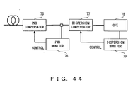
- Fig. 44 shows an example configuration of a compensation system using both a PMD compensator and a dispersion compensator together.
- controlling a PMD compensator 75 based on the result of a PMD monitor 76 detecting a DOP compensates for the PMD of an incoming optical signal input to a dispersion compensator 77, and a dispersion monitor 79 monitoring an optical/electrical converter (O/E) 78 correctly controls the dispersion compensator 77.
- O/E optical/electrical converter
- Fig. 45 is a sequence chart showing the control input for coping with such a problem that is shown in Fig. 44.
- step S43 the control of a PMD controller (PMDC) in the PMD compensator 75 is immediately started, and in step S44, the initial setting is completed. Then, in step S45, the PMDC enters into a tracking mode.
- PMDC PMD controller
- step S46 time T, the wait time for substantial compensation by the PMD compensator 75, is set in the dispersion compensator (VDC) 77, and then, in step S47, the control of the VDC is started. Then, in step S48, the initial setting of the VDC is completed, and in step S49, the VDC enters into a tracking mode. After steps S45 and S49, the PMDC and VDC both enter into a tracking mode.
- Figs. 46 and 47 show example configurations (No. 2 and 3) of the receiver of an optical communication system that compensates for both polarization-mode dispersion and chromatic dispersion. If both types of compensation are performed in this way, as described earlier, basically then, it is only the chromatic dispersion monitor 79 to be located after the PMD compensator since chromatic dispersion monitoring must be conducted after the completion of PMD compensation. The order of the dispersion compensator and the PMD compensator is regardless. In this way, the configurations shown in Figs. 46 and 47 are available.
- Fig. 48 shows an example of the system configuration of a receiver using PMD compensation and chromatic dispersion compensation together (no. 4).
- the dispersion compensator 77 collectively applies chromatic dispersion compensation to a plurality of channels and the PMD compensator 75 applies polarization mode dispersion compensation to each channel.
- the dispersion compensator 77 carries out chromatic dispersion compensation using the dispersion monitor 79 that uses the respective channel error rate of one or more channels after PMD compensation, that is, a transmission quality monitor.
- PMD compensation can be separated from chromatic dispersion compensation using the influence on transmission quality of a PMD monitor that is operated by a method other than that of detecting a DOP.
- Fig. 49 shows the influence on transmission quality that is used for creating this separation.
- chromatic dispersion has dependence between channels
- PMD has no dependence between channels.
- the timewise change in speed of influences on transmission quality is slow in both cases of chromatic dispersion and PMD if it is due to a temperature change.
- a pressure change such as fiber touch and the like
- the change in speed of the influences by PMD is fast. Therefore, the two types of compensation can be separated utilizing such differences in temperature.
- Figs. 50 through 52 show example configurations of an optical communication system compensating for polarization-mode dispersion and chromatic dispersion.
- Fig. 50 shows the first example configuration. In this case, chromatic dispersion is collectively compensated for all channels, as shown in Fig. 48, while polarization-mode dispersion is individually compensated for each channel. In this case, a transmission quality monitor is used instead of a chromatic dispersion monitor.
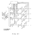
- Figs. 51 and 52 show the second and third example configurations, respectively. In each of these cases, chromatic dispersion and polarization-mode dispersion are compensated for in each channel. However, in the third example configuration, a controller 80 separates the control of the dispersion compensator 34 from that of the PMD compensator 75.
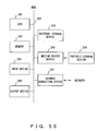
- the control of a variable chromatic dispersion compensator of the present invention can be realized using an information processor, such as a computer, as shown in Fig. 53.
- the computer shown in Fig. 53 comprises a CPU 201, a memory 202, an input device 203, an output device 204, an external storage device 205, a medium driver device 206 and a network connection device 207.
- a bus 209 connects the devices to one another.
- the memory 202 includes a ROM read-only memory) a RAM (random-access memory) and the like.
- the memory 202 stores a program and data to be used for the process.
- the CPU 201 performs necessary processes by using the memory 202 and executing the program.
- the input device 203 includes a keyboard, a pointing device and the like.
- the output device 204 includes a display and the like.
- the external storage device 205 includes a magnetic disk device, an optical disk device, a magneto-optical disk device and the like.
- the external storage device 205 stores the program and data, and can also load the program and data onto the memory 202 and use them, as requested.
- the medium driver device 206 drives a portable storage medium 208 and accesses the recorded contents.
- a portable storage medium 208 any computer-readable storage medium, such as a memory card, a memory stick, a flexible disk, a CD-ROM (compact disc read-only memory), an optical disk, a magneto-optical disk, a DVD (digital versatile disk) and the like, is used.
- This portable storage medium 208 stores the program and data, and can also load them into the memory 202 and use them, as requested.
- the network connection device 207 is used to connect the computer to a network.
- the network connection device 207 can also receive the program and data from an external device, and can load them into the memory 202 and use them, as requested.
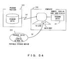
- Fig. 54 shows how to provide a program and data that are related to the present invention.
- the program and data are provided by any of the following three methods (a) through (c).
- the present invention is not restricted to the preferred embodiments described above, and a variety of configurations can be used as long as they do not deviate from the subject matter of the present invention.
- the chromatic dispersion can be optimally controlled using a general-purpose transmission quality monitor, instead of a special dispersion monitor, and accordingly, system performance can be improved.
- chromatic dispersion and polarization-mode dispersion can be compensated for by locating the transmission quality monitor after the polarization-mode dispersion compensator, and accordingly, the present invention greatly contributes to the realization of an ultra-high-speed optical communication system.
Landscapes
- Physics & Mathematics (AREA)
- Electromagnetism (AREA)
- Engineering & Computer Science (AREA)
- Computer Networks & Wireless Communication (AREA)
- Signal Processing (AREA)
- Optical Communication System (AREA)
Abstract
Description

Claims (11)
- An automatic dispersion compensation device (1) with a variable chromatic dispersion compensator (5) for incoming optical signals input from an optical transmitter transmitting optical signals for a plurality of channels though a transmission line, comprising:a transmission quality measurement unit (2) measuring transmission quality of incoming optical signals for each of the plurality of channels; anda chromatic dispersion compensation amount control unit (3) separating and detecting transmission quality degradation, due to chromatic dispersion in the transmission line, in the measurement result of the transmission quality measurement unit (2) from degradation due to other factors and controlling the variable chromatic dispersion compensator (5) in such a way as to compensate for the degradation.
- The automatic dispersion compensation device (1) according to claim 1, further comprising:a residual chromatic dispersion amount increase/decrease unit increasing/decreasing the difference in the amount of dispersion compensation between channels for any residual amount of chromatic dispersion obtained as a result of compensation by the variable chromatic dispersion compensator (5), depending on the optical signal wavelength; anda chromatic dispersion amount increase/decrease judgment unit comparing the measurement result of transmission quality after compensation by the variable chromatic dispersion compensator (5) and the residual chromatic dispersion amount increase/decrease unit, between channels, and judging whether the amount of chromatic dispersion in the transmission line increases or decreases.
- The automatic dispersion compensation device (1) according to claim 2, wherein
said residual chromatic dispersion amount increase/decrease unit changes the difference in the amount of dispersion between channels in the form of a slope across the entire channel range, based on an increase in the number of the channels depending on wavelength. - The automatic dispersion compensation device (1) according to claim 2, wherein
said residual chromatic dispersion amount increase/decrease unit changes the difference in the amount of dispersion between channels in the form of a step across the entire channel range, based on an increase in the number of the channels depending on wavelength. - The automatic dispersion compensation device (1) according to claim 2, wherein
said residual wavelength dispersion amount increase/decrease unit changes the difference in the amount of dispersion between channels in the form of slope in a specific part of the channel range, based on an increase in the number of the channels depending on wavelength. - The automatic dispersion compensation device (1) according to claim 2, wherein
said residual wavelength dispersion amount increase/decrease unit changes the difference in the amount of dispersion between channels in the form of a step in a specific part of the channel range, based on an increase in the number of the channels depending on wavelength. - The automatic dispersion compensation device (1) according to claim 1, further comprising:said chromatic dispersion compensation amount control unit (3) stops control by a variable chromatic dispersion compensator (5) in accordance with the detection result of the receiver state and the measurement result of said transmission quality measurement unit (2).a receiver state detection unit (fig.42) detecting the state of each unit of a receiver receiving optical signals transmitted through the transmission line, wherein
- The automatic dispersion compensation device (1) according to claim 1, further comprising in addition to the variable chromatic dispersion compensator (5):said chromatic dispersion compensation amount control unit (3) controls the variable chromatic dispersion compensator and polarization-mode dispersion compensator (75) in accordance with the detection result of the polarization-mode dispersion monitor (76) and a timewise change tendency of said transmission quality measurement unit (2).a polarization-mode dispersion compensator (75) corresponding to signals from each of one or more channels input from the transmission line; anda polarization-mode dispersion monitor (76) detecting an amount of polarization-mode dispersion after compensation by the polarization-mode dispersion compensator (75), wherein
- An automatic dispersion compensation method compensating for a variable chromatic dispersion of incoming optical signals input from an optical transmitter transmitting optical signals for a plurality of channels though a transmission line, comprising:measuring transmission quality of incoming optical signals for each of the plurality of channels;separating and detecting transmission quality degradation, due to chromatic dispersion in the transmission line, in a measurement result of the transmission quality measurement unit from degradation due to other factors; andcontrolling the variable chromatic dispersion compensation in such a way as to compensate for the degradation.
- A computer-readable storage medium on which is recorded a program enabling the computer to compensate for variable chromatic dispersion of incoming optical signals input from an optical transmitter transmitting optical signals for a plurality of channels though a transmission line, comprising:receiving a transmission quality measurement result from incoming optical signals for each of the plurality of channels;separating and detecting transmission quality degradation, due to chromatic dispersion in the transmission line, in a measurement result of the transmission quality from degradation due to other factors; andcontrolling the variable chromatic dispersion compensation in such a way as to compensate for the degradation.
- An automatic dispersion compensation device (1) with a variable chromatic dispersion compensator (5) for incoming optical signals input from an optical transmitter transmitting optical signals for a plurality of channels though a transmission line, comprising:a transmission quality measurement means (2) for measuring transmission quality of incoming optical signals for each of the plurality of channels; anda chromatic dispersion compensation amount control means (3) for separating and detecting transmission quality degradation, due to chromatic dispersion in the transmission line, in a measurement result of the transmission quality measurement means (2) from degradation due to other factors and controlling the variable chromatic dispersion compensator (5) in such a way as to compensate for the degradation.
Applications Claiming Priority (2)
| Application Number | Priority Date | Filing Date | Title |
|---|---|---|---|
| JP2002159062A JP3923373B2 (en) | 2002-05-31 | 2002-05-31 | Automatic dispersion compensation device and compensation method |
| JP2002159062 | 2002-05-31 |
Publications (2)
| Publication Number | Publication Date |
|---|---|
| EP1367744A2 true EP1367744A2 (en) | 2003-12-03 |
| EP1367744A3 EP1367744A3 (en) | 2005-08-17 |
Family
ID=29417248
Family Applications (1)
| Application Number | Title | Priority Date | Filing Date |
|---|---|---|---|
| EP03011116A Withdrawn EP1367744A3 (en) | 2002-05-31 | 2003-05-22 | Automatic dispersion compensation device and compensation method |
Country Status (4)
| Country | Link |
|---|---|
| US (1) | US7433599B2 (en) |
| EP (1) | EP1367744A3 (en) |
| JP (1) | JP3923373B2 (en) |
| CN (1) | CN1467935A (en) |
Cited By (2)
| Publication number | Priority date | Publication date | Assignee | Title |
|---|---|---|---|---|
| CN101160757B (en) * | 2005-04-28 | 2012-05-30 | 斯欧普迪克尔股份有限公司 | Common electronic dispersion compensation device for multiple optical communication channels |
| US11522332B2 (en) | 2021-04-01 | 2022-12-06 | Nguyen Tan Hung | Optical receiver using a photonic integrated circuit with array of semiconductor optical amplifiers |
Families Citing this family (27)
| Publication number | Priority date | Publication date | Assignee | Title |
|---|---|---|---|---|
| US7274879B1 (en) * | 2003-10-23 | 2007-09-25 | Nortel Networks Limited | Compensation of temperature-induced dispersion drift in optical communication links |
| US7885541B2 (en) * | 2004-02-23 | 2011-02-08 | Dynamic Method Enterprises Limited | Method and apparatus for optical performance monitoring |
| JP4696114B2 (en) * | 2005-06-23 | 2011-06-08 | 富士通株式会社 | Chromatic dispersion compensation control method and apparatus |
| JP4780518B2 (en) * | 2005-09-14 | 2011-09-28 | 日本電気株式会社 | Optical transmission device, optical transmission system, and alarm issuing method |
| US7606498B1 (en) * | 2005-10-21 | 2009-10-20 | Nortel Networks Limited | Carrier recovery in a coherent optical receiver |
| ES2385493T5 (en) * | 2005-12-20 | 2015-05-14 | Zte Corporation | Self-adaptive dispersion compensation device and procedure |
| CN100460902C (en) * | 2006-03-10 | 2009-02-11 | 中兴通讯股份有限公司 | Adjustment method and device for residual dispersion compensation of wavelength division multiplexing system |
| US20080025730A1 (en) * | 2006-06-29 | 2008-01-31 | Giovannini Thomas J | Method and apparatus for autonomous adaptation of an optical dispersion compensation ("ODC") module |
| JP2008098975A (en) * | 2006-10-12 | 2008-04-24 | Fujitsu Ltd | Reception device, transmission device, reception method, and transmission method |
| JP5012811B2 (en) | 2006-11-30 | 2012-08-29 | 日本電気株式会社 | Dispersion detection device and automatic dispersion compensation system using the same |
| JP4648363B2 (en) * | 2007-06-13 | 2011-03-09 | 株式会社日立製作所 | Optical transmission device and optical transmission device control method |
| JP4900180B2 (en) * | 2007-10-12 | 2012-03-21 | 富士通株式会社 | Optical receiver and optical transmission system |
| JP5168468B2 (en) * | 2007-12-27 | 2013-03-21 | 日本電気株式会社 | Polarization dispersion monitoring method and apparatus |
| JP5025503B2 (en) * | 2008-01-21 | 2012-09-12 | 三菱電機株式会社 | Dispersion compensation device |
| JP5282561B2 (en) * | 2008-12-22 | 2013-09-04 | 富士通株式会社 | Transmission apparatus and dispersion value setting method |
| JP2010206371A (en) * | 2009-03-02 | 2010-09-16 | Nec Corp | Wavelength multiplex optical communication system, optical signal dispersion compensation method for same, and program |
| EP2299577B1 (en) * | 2009-09-18 | 2012-08-01 | DET International Holding Limited | Digital slope compensation for current mode control |
| JP5495120B2 (en) * | 2010-05-24 | 2014-05-21 | 日本電気株式会社 | Optical receiver, optical reception method, and control program for optical receiver |
| JP5485047B2 (en) * | 2010-06-28 | 2014-05-07 | 富士通テレコムネットワークス株式会社 | Wavelength division multiplexing transmission apparatus and dispersion compensation control method |
| JP5648436B2 (en) | 2010-11-12 | 2015-01-07 | 富士通株式会社 | Pre-emphasis control method |
| JP5861516B2 (en) | 2012-03-16 | 2016-02-16 | 富士通株式会社 | Optical transmission apparatus and characteristic compensation method |
| US10038503B2 (en) * | 2014-08-13 | 2018-07-31 | Xilinx, Inc. | Adaptive optical channel compensation |
| WO2016157800A1 (en) * | 2015-03-27 | 2016-10-06 | 日本電気株式会社 | Optical receiving apparatus |
| CN108106844B (en) * | 2017-11-22 | 2019-09-13 | 辽宁大学 | A Bearing Fault Diagnosis Method for Automatic Encoding Machine with Adaptive Parameter Adjustment |
| CN110346653B (en) * | 2019-06-19 | 2021-08-17 | 中国科学院国家天文台 | Solar wind dispersion measurement method, device, electronic equipment and medium |
| US20230084066A1 (en) * | 2021-09-14 | 2023-03-16 | Huawei Technologies Co., Ltd. | System and method for dispersion compensation in fibered optical communication paths |
| US12597999B1 (en) * | 2025-08-08 | 2026-04-07 | Linktel Technologies, Inc. | Optical transceiver with dispersion management |
Family Cites Families (14)
| Publication number | Priority date | Publication date | Assignee | Title |
|---|---|---|---|---|
| JP3262444B2 (en) | 1994-02-08 | 2002-03-04 | 日本電信電話株式会社 | Automatic equalizer |
| EP0684709B1 (en) * | 1994-05-25 | 2002-10-02 | AT&T Corp. | Optical communications system with adjustable dispersion compensation |
| JP3326319B2 (en) | 1995-06-30 | 2002-09-24 | 古河電気工業株式会社 | Method and apparatus for measuring polarization mode dispersion |
| JP3464744B2 (en) | 1996-06-03 | 2003-11-10 | 日本電信電話株式会社 | Automatic equalization system |
| JPH118590A (en) | 1997-04-25 | 1999-01-12 | Oki Electric Ind Co Ltd | Optical transmission system and supervisory and control method therefor |
| JPH1188260A (en) * | 1997-09-09 | 1999-03-30 | Fujitsu Ltd | Optical transmission line dispersion compensator |
| US6307988B1 (en) | 1999-02-18 | 2001-10-23 | Lucent Technologies Inc. | Optical fiber communication system incorporating automatic dispersion compensation modules to compensate for temperature induced variations |
| US6370300B1 (en) * | 1999-02-18 | 2002-04-09 | Lucent Technologies Inc. | Optical communication system incorporating automatic dispersion compensation modules |
| JP4294153B2 (en) * | 1999-04-12 | 2009-07-08 | 富士通株式会社 | WDM optical transmission system |
| US6483958B2 (en) | 2000-05-06 | 2002-11-19 | Tektronix Munich | PMD compensator |
| TW508920B (en) | 2000-06-01 | 2002-11-01 | Sumitomo Electric Industries | Optical transmission system |
| JP4592887B2 (en) * | 2000-08-07 | 2010-12-08 | 富士通株式会社 | Method and system for compensating chromatic dispersion |
| US20020018267A1 (en) * | 2000-08-09 | 2002-02-14 | Yafo Networks, Inc. | Methods and apparatus for adaptive optical distortion compensation using magneto-optic device |
| JP4011290B2 (en) | 2001-01-10 | 2007-11-21 | 富士通株式会社 | Dispersion compensation method, dispersion compensation apparatus, and optical transmission system |
-
2002
- 2002-05-31 JP JP2002159062A patent/JP3923373B2/en not_active Expired - Fee Related
-
2003
- 2003-05-22 EP EP03011116A patent/EP1367744A3/en not_active Withdrawn
- 2003-05-29 US US10/446,694 patent/US7433599B2/en not_active Expired - Fee Related
- 2003-05-30 CN CNA031385710A patent/CN1467935A/en active Pending
Cited By (2)
| Publication number | Priority date | Publication date | Assignee | Title |
|---|---|---|---|---|
| CN101160757B (en) * | 2005-04-28 | 2012-05-30 | 斯欧普迪克尔股份有限公司 | Common electronic dispersion compensation device for multiple optical communication channels |
| US11522332B2 (en) | 2021-04-01 | 2022-12-06 | Nguyen Tan Hung | Optical receiver using a photonic integrated circuit with array of semiconductor optical amplifiers |
Also Published As
| Publication number | Publication date |
|---|---|
| JP3923373B2 (en) | 2007-05-30 |
| EP1367744A3 (en) | 2005-08-17 |
| CN1467935A (en) | 2004-01-14 |
| US20030223760A1 (en) | 2003-12-04 |
| JP2004007150A (en) | 2004-01-08 |
| US7433599B2 (en) | 2008-10-07 |
Similar Documents
| Publication | Publication Date | Title |
|---|---|---|
| US7433599B2 (en) | Automatic dispersion compensation device and compensation method | |
| JP4011290B2 (en) | Dispersion compensation method, dispersion compensation apparatus, and optical transmission system | |
| US6925262B2 (en) | Method and system for compensating chromatic dispersion | |
| EP2569879B1 (en) | Method and apparatus for determining an optical signal-to-noise ratio (osnr) penalty | |
| EP1465360A2 (en) | Chromatic dispersion compensation controlling system | |
| US7936993B2 (en) | Chromatic dispersion compensating apparatus | |
| JP5012811B2 (en) | Dispersion detection device and automatic dispersion compensation system using the same | |
| US20100135663A1 (en) | Repeater and repeating method | |
| JP5648436B2 (en) | Pre-emphasis control method | |
| JP2007202009A (en) | WDM transmission system | |
| Eiselt et al. | Experimental comparison of WDM system capacity in conventional and nonzero dispersion shifted fiber | |
| JP5025503B2 (en) | Dispersion compensation device | |
| JP4900180B2 (en) | Optical receiver and optical transmission system | |
| JP5263289B2 (en) | Optical fiber dispersion detector and automatic dispersion compensation system using the same | |
| JP2004266603A (en) | Wavelength multiplexing optical repeater transmission method and repeater | |
| US7519295B2 (en) | Apparatus and method for commissioning an optical transmission system | |
| JP3771830B2 (en) | Optical wavelength division multiplexing transmission system with automatic dispersion compensation circuit | |
| US20070047963A1 (en) | Optical transceiver having parallel electronic dispersion compensation channels | |
| US20040179837A1 (en) | Method and arrangement for the determination and separation of single-channel effects on the optical transmission of a wavelength division multiplex (WDM) signal | |
| JP2004128974A (en) | Dispersion monitoring device, dispersion monitoring method, and automatic dispersion compensation system | |
| Westbrook et al. | Measurement of pulse degradation using all-optical 2R regenerator | |
| Sano et al. | Adaptive Dispersion Equalization by Monitoring Relative Phase Shift Between Spacing-FixedWDM Signals | |
| EP1677444B1 (en) | Advanced dispersion map for transmission system with dispersion shifted fibres | |
| Renaudier et al. | On the required number of WDM channels when assessing performance of 100Gb/s coherent PDM-QPSK overlaying legacy systems | |
| Cartaxo et al. | Modulation formats for upgrading MANs to 40 Gb/s per channel |
Legal Events
| Date | Code | Title | Description |
|---|---|---|---|
| PUAI | Public reference made under article 153(3) epc to a published international application that has entered the european phase |
Free format text: ORIGINAL CODE: 0009012 |
|
| AK | Designated contracting states |
Kind code of ref document: A2 Designated state(s): AT BE BG CH CY CZ DE DK EE ES FI FR GB GR HU IE IT LI LU MC NL PT RO SE SI SK TR |
|
| AX | Request for extension of the european patent |
Extension state: AL LT LV MK |
|
| 17P | Request for examination filed |
Effective date: 20050331 |
|
| PUAL | Search report despatched |
Free format text: ORIGINAL CODE: 0009013 |
|
| AK | Designated contracting states |
Kind code of ref document: A3 Designated state(s): AT BE BG CH CY CZ DE DK EE ES FI FR GB GR HU IE IT LI LU MC NL PT RO SE SI SK TR |
|
| AX | Request for extension of the european patent |
Extension state: AL LT LV MK |
|
| AKX | Designation fees paid |
Designated state(s): DE FR GB |
|
| GRAP | Despatch of communication of intention to grant a patent |
Free format text: ORIGINAL CODE: EPIDOSNIGR1 |
|
| STAA | Information on the status of an ep patent application or granted ep patent |
Free format text: STATUS: THE APPLICATION IS DEEMED TO BE WITHDRAWN |
|
| 18D | Application deemed to be withdrawn |
Effective date: 20070123 |