EP1367721A1 - Interpolating function generating apparatus and method, digital-analog converter, data interpolator, program, and record medium - Google Patents
Interpolating function generating apparatus and method, digital-analog converter, data interpolator, program, and record medium Download PDFInfo
- Publication number
- EP1367721A1 EP1367721A1 EP02702727A EP02702727A EP1367721A1 EP 1367721 A1 EP1367721 A1 EP 1367721A1 EP 02702727 A EP02702727 A EP 02702727A EP 02702727 A EP02702727 A EP 02702727A EP 1367721 A1 EP1367721 A1 EP 1367721A1
- Authority
- EP
- European Patent Office
- Prior art keywords
- data
- digital
- oversampling
- input
- processed
- Prior art date
- Legal status (The legal status is an assumption and is not a legal conclusion. Google has not performed a legal analysis and makes no representation as to the accuracy of the status listed.)
- Withdrawn
Links
Images


Classifications
-
- H—ELECTRICITY
- H03—ELECTRONIC CIRCUITRY
- H03M—CODING; DECODING; CODE CONVERSION IN GENERAL
- H03M1/00—Analogue/digital conversion; Digital/analogue conversion
- H03M1/66—Digital/analogue converters
-
- H—ELECTRICITY
- H03—ELECTRONIC CIRCUITRY
- H03H—IMPEDANCE NETWORKS, e.g. RESONANT CIRCUITS; RESONATORS
- H03H17/00—Networks using digital techniques
- H03H17/02—Frequency selective networks
- H03H17/06—Non-recursive filters
- H03H17/0621—Non-recursive filters with input-sampling frequency and output-delivery frequency which differ, e.g. extrapolation; Anti-aliasing
- H03H17/0635—Non-recursive filters with input-sampling frequency and output-delivery frequency which differ, e.g. extrapolation; Anti-aliasing characterized by the ratio between the input-sampling and output-delivery frequencies
- H03H17/065—Non-recursive filters with input-sampling frequency and output-delivery frequency which differ, e.g. extrapolation; Anti-aliasing characterized by the ratio between the input-sampling and output-delivery frequencies the ratio being integer
- H03H17/0657—Non-recursive filters with input-sampling frequency and output-delivery frequency which differ, e.g. extrapolation; Anti-aliasing characterized by the ratio between the input-sampling and output-delivery frequencies the ratio being integer where the output-delivery frequency is higher than the input sampling frequency, i.e. interpolation
-
- G—PHYSICS
- G06—COMPUTING OR CALCULATING; COUNTING
- G06F—ELECTRIC DIGITAL DATA PROCESSING
- G06F1/00—Details not covered by groups G06F3/00 - G06F13/00 and G06F21/00
- G06F1/02—Digital function generators
-
- H—ELECTRICITY
- H03—ELECTRONIC CIRCUITRY
- H03M—CODING; DECODING; CODE CONVERSION IN GENERAL
- H03M3/00—Conversion of analogue values to or from differential modulation
- H03M3/30—Delta-sigma modulation
- H03M3/50—Digital/analogue converters using delta-sigma modulation as an intermediate step
- H03M3/508—Details relating to the interpolation process
Definitions
- the present invention relates to an interpolating function generating apparatus and method, a digital-analog converter, a data interpolator, a program, and a record medium.
- it relates to a technology for interpolating discrete digital data to convert it into continuous analog signals.
- a digital-analog converter to which an oversampling technology is applied is used to obtain a continuous analog audio signal from discrete digital audio data.
- D/A converter digital-analog converter
- data interpolation is performed normally by using a digital filter to raise a pseudo-sampling frequency by interpolating data among discretely input digital data.
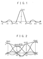
- FIG. 1 is an explanatory view of a sinc function.
- a sinc function appears when a Dirac delta function is inversely Fourier transformed, and can be defined by sin (?ft)/(?ft) where a sampling frequency is represented by f.
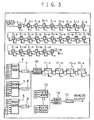
- FIG. 2 shows a relationship between the discrete data and interpolation values in the data.
- the values of the discrete data at the respective sampling points t1, t2, t3, and t4 arranged at equal intervals are Y (t1), Y (t2), Y (t3), and Y (t4), and the interpolation value y corresponding to a predetermined position t0 (at a distance a from t2) between the sampling points t2 and t3 is obtained as follows.
- the interpolation value y is obtained by using a sampling function
- the value of the sampling function at the interpolation position t0 is obtained for each piece of given discrete data, and a convolution arithmetic is performed by using the obtained values.
- the peak in the central position of the sampling function is set at the same level for each sampling point of t1 to t4, and the value (indicated by ?) of the sampling function at each interpolation position t0 is obtained and added up.
- the interpolation position t0 changes with a lapse of time
- the level of each sampling position also changes with a lapse of time. Therefore, the interpolation value y (t0) also continuously changes, thereby obtaining continuous analog signals smoothly connecting each piece of discrete data.
- an obtained interpolation value includes an abortion error, thereby failing in obtaining a correct interpolation value.
- the present invention has been achieved to solve the above mentioned problems, and aims at generating smooth analog signals free of deterioration in phase characteristic by a low pass filter or free of distortion of waveform by abortion error in the interpolation performed using a sinc function.
- the present invention also aims at obtaining an interpolating function for use in generating the above mentioned smooth analog signals through a simpler logic or algorithm.
- the interpolating function generating apparatus includes: data input means for oversampling a piece of digital data, and obtaining a part of the oversampling data as input data; and arithmetic means for processing the input data obtained from the data input means using a digital basic waveform, and obtaining an interpolating function by performing a moving-average calculation or a convolution arithmetic on the processed digital data.
- the data input means can obtain a first half or a second half of the oversampling data as the input data.
- the arithmetic means includes: first addition means for adding the digital data processed using the digital basic waveform to several pieces of data obtained by shifting the processed data by the phase of an oversampling cycle to perform the moving-average calculation or the convolution arithmetic; second addition means for adding up several pieces of data obtained by shifting the digital data processed using the digital basic waveform by the phase of an oversampling cycle; and third addition means for adding up the outputs of the first addition means and the second addition means.
- the interpolating function generating method includes: a first step of oversampling a piece of digital data, and obtaining a part of the oversampling data as input data; a second step of processing the input data using a digital basic waveform; and a third step of obtaining an interpolating function by performing a moving-average calculation or a convolution arithmetic on the digital data processed using the digital basic waveform.
- a first half or a second half of the oversampling data as the input data can be obtained in the first step.
- the digital data processed in the second step is added to several pieces of data obtained by shifting the processed digital data by the phase of the oversampling cycle, the several pieces of data obtained by shifting the digital data processed using the digital basic waveform by the phase of the oversampling cycle are added up, and the addition results are further added up.
- the digital-analog converter includes: data input means for oversampling each of plural pieces of discrete data and obtaining a part of the oversampling data as input data for each piece of the discrete data; and arithmetic means for processing the input data obtained by the data input means using a digital basic waveform, and combining the processed digital data in a moving-average calculation or a convolution arithmetic, thereby obtaining an interpolation value for the discrete data.
- the data input means oversamples each of the plural pieces of discrete data provided for each clock of a predetermined frequency, and obtains a part of the oversampling data as the input data for each clock period sectioned by the clock of the predetermined frequency.
- the data input means can obtain a first half or a second half of the oversampling data as the input data for each clock period.
- the arithmetic means includes : first addition means for adding the digital data processed using the digital basic waveform to several pieces of data obtained by shifting the processed data by the phase of an oversampling cycle to perform the moving-average calculation or the convolution arithmetic; second addition means for adding up several pieces of data obtained by shifting the digital data processed using the digital basic waveform by the phase of an oversampling cycle; and third addition means for adding up the outputs of the first addition means and the second addition means.
- the data interpolator includes: data input means for oversampling each of plural pieces of discrete data and obtaining a part of the oversampling data as input data for each piece of the discrete data; and arithmetic means for processing the input data obtained by the data input means using a digital basic waveform, and combining the processed digital data in a moving-average calculation or a convolution arithmetic, thereby obtaining an interpolation value for the discrete data.
- the data input means oversamples each of the plural pieces of discrete data provided for each clock of a predetermined frequency, and obtains a part of the oversampling data as the input data for each clock period sectioned by the clock of the predetermined frequency.
- the data input means can obtain a first half or a second half of the oversampling data as the input data for each clock period.
- the arithmetic means includes: first addition means for adding the digital data processed using the digital basic waveform to several pieces of data obtained by shifting the processed data by the phase of an oversampling cycle to perform the moving-average calculation or the convolution arithmetic; second addition means for adding up several pieces of data obtained by shifting the digital data processed using the digital basic waveform by the phase of an oversampling cycle; and third addition means for adding up the outputs of the first addition means and the second addition means.
- the interpolating function generating program is used to direct a computer to function as data input means for oversampling a piece of digital data, and obtaining a part of the oversampling data as input data; and arithmetic means for processing the input data obtained from the data input means using a digital basic waveform, and obtaining an interpolating function by performing a moving-average calculation or a convolution arithmetic on the processed digital data.
- the data interpolating program according to the present invention is used to direct a computer to function as data input means for oversampling each of plural pieces of discrete data and obtaining a part of the oversampling data as input data for each piece of the discrete data; and arithmetic means for processing the input data obtained by the data input means using a digital basic waveform, and combining the processed digital data in a moving-average calculation or a convolution arithmetic, thereby obtaining an interpolation value for the discrete data.
- the computer-readable record medium records a program for directing a computer to function as each means as set forth in claim 15 or 16.
- the present invention obtains an interpolation value by oversampling input digital data, and performing a moving-average calculation or a convolution arithmetic while processing the oversampling data using a digital basic waveform as described above. Since continuous interpolation values can be obtained only by performing the above mentioned digital process, smooth analog signals can be obtained as a result of D/A conversions on the values without a low pass filter, and without the deterioration of the phase characteristic by the filter. Furthermore, since the function generated using a digital basic waveform according to the present invention is a finite sampling function, the number of pieces of discrete data required to obtain an interpolation value can be reduced. Furthermore, although the number of pieces of discrete data to be processed is reduced, no abortion errors occur, thereby minimizing the distortion of an output waveform. Therefore, the quality of an output analog audio signal can be largely improved.
- a part of oversampling data is obtained as input data, and a process using a digital basic waveform, and a moving-average calculation or a convolution arithmetic are performed using apart of the oversampling data. Therefore, the process using a digital basic waveform, and a moving-average calculation or a convolution arithmetic can be performed in the simplest process.
- the present invention when the present invention is configured by hardware, it can be realized by an easier logic, thereby minimizing the circuit scale.
- the present invention is configured by software, it can be realized by the simplest algorithm, thereby reducing the load of the process and performing the arithmetic operations at a higher speed.
- an input discrete digital data is processed by using a digital basic waveform as shown in FIG. 6, and a predetermined moving-average calculation or a convolution arithmetic is performed on the processed data, thereby obtaining an interpolating function as indicated by the solid line C shown in FIG. 7.
- the function indicated by a solid line C shown in FIG. 7 is a sampling function, and is a once differentiable finite function (the value of a function having a finite value other than 0 in a local area, and having a value of 0 in other areas) function converging into 0 in the finite sampling position. Therefore, an interpolating process can be performed by using a once differentiable function in the discrete data by a superposing process based on each piece of discrete data using the sampling function shown in FIG. 7 instead of the conventional sinc function shown in FIG. 1.
- continuous interpolation values can be obtained only by performing a predetermined digital process, and smooth analog signals can be obtained by D/A converting the values without using any low pass filter. Furthermore, since an interpolating function generated from a digital basic waveform is a finite sampling function, a correct interpolation value can be obtained only using finite discrete data without an abortion error, thereby minimizing the distortion of an output waveform.
- FIG. 3 shows an example of a configuration of an interpolating function generating apparatus 100 according to the present embodiment.
- a D-type flipflop (hereinafter referred to as a D?FF) 1 holds input digital data according to the clock ck of a predetermined frequency (for example, 44.1 KHz).
- An AND gate 2 outputs a logical product of the digital data input from the D?FF 1 and the clock ck to a D?FF 3 -1 .
- the D?FF 3 -1 holds the digital data output by the AND gate 2 according to, for example, the clock 8ck of a 8-fold frequency.
- the data input means of the present invention is configured by the D?FF 1, the AND gate 2, and the D?FF 3 -1 .
- FIG. 4A to 4C are timing charts showing an operation of a data input means.
- the digital data shown in FIG. 4B is held in the D?FF 1 in synchronization with the rising edge of the clock ck shown in FIG. 4A.
- the AND gate 2 outputs the digital data only while the clock ck indicates 'H' based on the logical product of the digital data held by the D?FF 1 and the clock ck.
- the D?FF 3 -1 holds the digital data output by the AND gate 2 according to the clock 8ck having an 8-fold frequency as shown in FIG. 4C.
- the data input means obtains a first half (corresponding to four clocks) of the 8-fold oversampling data as input data.
- the first half of the 8-fold oversampling data is obtained as input data in an AND operation between the digital data and the clock ck.
- a second half of the 8-fold oversampling data can also be obtained as input data in the NAND operation.
- the data B1 to B24 output after sequentially delayed by these twenty-four D?FF 3 -1 to 3 -24 are appropriately distributed and input into first to third adders 4 to 6.
- the first adder 4 receives data B1 to B4 output from four D?FF 3 -1 to 3 -4 positioned closest to the input side and data B21 to B24 output from four D?FF 3 -21 to 3 -24 positioned closest to the output side, adds up the data, and outputs an addition result. That is, the first adder 4 generates the portion of '-1, -1' corresponding to the both sides of the digital basic waveform shown in FIG. 6.
- a second adder 5 receives data B9 to B16 output from eight D?FF 3 -9 to 3 -16 positioned at the center, adds up the data, and output an addition result. That is, the second adder 5 corresponds to the portion which generates '8, 8' corresponding to the central portion of the digital basic waveform shown in FIG. 6.
- a third adder 6 receives data B5 to B8 output from the D?FF 3 -5 to 3 -8 which are the fifth to eighth D?FF from the input side and data B17 to B20 output from D?FF 3 -17 to 3 -20 which are the fifth to eighth D?FF from the output side, adds up the data, and outputs an addition result. That is, the third adder 6 corresponds to the portion which generates '1, 1' of the digital basic waveform shown in FIG. 6.
- a -1/32-fold multiplier 7 multiplies the addition result output from the first adder 4 by -1/32.
- a 1/4-fold multiplier 8 multiplies the addition result output from the second adder 5 by 1/4.
- a 1/32-fold multiplier 9 multiplies the addition result output from the third adder 6 by 1/32.
- the fourth adder 10 adds the multiplication result output from each of the multipliers 7 to 9.
- the multiplication rates '-1/32', '1/4', and '1/32' of the multipliers 7 to 9 correspond to the rates '-1', '8', and '1' of the digital basic waveforms shown in FIG. 6. Therefore, by a fourth adder 10 adding up the multiplication results obtained by each of the multipliers 7 to 9, the digital data input by the data input means is processed using the digital basic waveform shown in FIG. 6. If a piece of digital data having the amplitude of '1' is input, the digital waveform obtained by the fourth adder 10 is the waveform itself shown in FIG. 6.
- delay circuits 11 -1 to 11 -4 serially connected to the last stage of the fourth adder 10 sequentially delay by one clock the data output from the fourth adder 10 according to the 8-fold frequency clock 8ck.
- These delay circuits 11 -1 to 11 -4 are configured by an analog delay such as a sample hold, etc. in an analog process, and a D?FF in a digital process.
- the data C20 output from the fourth adder 10 and the data C21 to C24 sequentially delayed and output by each of the delay circuits 11 -1 to 11 -4 are appropriately distributed and input by the fifth and sixth fifth adders 12 and 13.
- the fifth adder 12 adds up the data C20 (digital data processed using the digital basic waveform) output from the fourth adder 10, and data C21 to C23 (three pieces of digital data obtained by shifting by the phase of the oversampling cycle) output from each of the delay circuits 11 -1 to 11 -3 .
- a fifth adder 12 corresponds to the first addition means according to the present invention.
- a sixth adder 13 adds up the data C21 to C24 (four pieces of digital data obtained by shifting the digital data processed using the digital basic waveform by the phase of the oversampling cycle) output from the delay circuits 11 -1 to 11 -4 .
- the sixth adder 13 corresponds to the second addition means according to the present invention.
- a seventh adder 14 adds the output result of the fifth and sixth adders 12 and 13.
- the seventh adder 14 corresponds to the third addition means according to the present invention.
- a 1/8-fold multiplier 15 multiplies the addition result output from the seventh adder 14 by 1/8.
- the process is performed to match the amplitude increased by the addition through the moving-average calculation or the convolution arithmetic with the amplitude of the original digital input.
- smooth interpolation values close to the analog generated from the original data are output from the 1/8-fold multiplier 15.
- the configuration in and after the D?FF 3 -1 corresponds to the arithmetic means according to the present invention for performing a moving-average calculation or a convolution arithmetic after processing the oversampling data using the digital basic waveform.
- FIG. 5A and 5B show the operation performed when the process is performed by software.
- FIG. 5A is a flowchart
- FIG. 5B shows a sequence of values obtained in each operation step of the flowchart.
- the sequence of values shown in FIG. 5B shows an example of a result of processing a piece of digital data whose amplitude is '1'.
- the sequence of values shown in FIG. 5B is represented by a waveform graph as shown in FIG. 7.
- step S1 the first half of the data in the 8-fold oversampling data included in one clock ck period is obtained as input data.
- the sequence of values of the input data is shown in the second column from the left in FIG. 5B.
- the sequence of 0s in lines 1 to 24 are provided with the delay corresponding to D?FF 3 -1 to 3 -24 taken into account.
- the waveform corresponding to the sequence of values is indicated by the solid line A in FIG. 7.
- step S2 the arithmetic of -SUM (B1:B4)/4-SUM (B21:B24)/4 + SUM (B5:B8)/4 + SUM (B17:B20)/4 + SUM (B9:B16) * 2 is performed (B1 through B24 correspond to the data output from the D?FF 3 -1 to 3 -24 shown in FIG. 3).
- the sequence of values of the intermediate value data obtained by the arithmetic is shown on the third column in FIG. 5B.
- the waveform corresponding to the sequence of values is indicated by the alternate long and short dash line B shown in FIG. 7.
- the multiplication rates are -1/4, 2, and 1/4, and they are 8-fold values as compared with the values shown in FIG. 3. They are set larger only for visibility of the graph shown in FIG. 7 by setting larger scaling factors for convenience.
- step S3 the arithmetic of (SUM(C20:C23)+SUM(C21:C24))/8 is performed (C20 to C24 correspond to the data output from the fourth adder 10 and the delay circuits 11 -1 to 11 -4 shown in FIG. 3).
- the sequence of values of the output data obtained in the arithmetic is shown in column 4 in FIG. 5B. Furthermore, the waveform corresponding to the sequence of values is indicated by the solid line C shown in FIG. 7.
- the arithmetic is performed with the intermediate value data in lines 20 to 24 set as C20 to C24.
- the arithmetic is performed with the intermediate value data in lines 24 to 28 set as C20 to C24.
- the horizontal axis indicates the clock 8ck of an 8-fold frequency while the vertical axis indicates the amplitude of the data.
- the input waveform A in this case corresponds to the waveform of the 8-fold oversampling data of the first half in one clock ck held in the D?FF 3 -1 shown in FIG. 3.
- the waveform B of the intermediate value corresponds to the waveform (8-fold) of the data output from the fourth adder 10 shown in FIG. 3.
- the output waveform C corresponds to the waveform (8-fold) of the data output from the 1/8-fold multiplier 15 shown in FIG. 3.
- the apparatus shown in FIG. 3 can be used as a D/A converter or a data interpolator as is. That is, by using the function indicated by the output data shown in FIG. 7 as an interpolating function and interpolating discrete digital data sequentially input at each clock ck, the digital data can be converted into smooth analog signals.
- the discrete digital data is 8-fold oversampled, and only the first half of the data is used, thereby forming a blank of four clocks for an adjacent input and sequentially inputting data. Then, data is combined in a moving-average calculation or a convolution arithmetic while each piece of oversampling data is processed using a digital basic waveform.
- a plurality of digital basic waveforms having amplitudes depending on the values of the input discrete data are combined in a moving-average calculation or a convolution arithmetic while they are shifted by half (4 clocks) of the 8-fold frequency clock 8ck.
- the discrete digital data is interpolated depending on the interpolating function as shown in FIG. 7.
- continuous interpolation values can be obtained only by performing the above mentioned digital process, and smooth analog signals can be obtained by D/A converting the values without using a low pass filter. Therefore, the deterioration of a phase characteristic by a low pass filter can be suppressed. Furthermore, since an interpolating function generated from a digital basic waveform is a finite sampling function, a correct interpolation value can be obtained only by using finite discrete data without an abortion error, thereby minimizing the distortion of an output waveform. Thereby, for example, when digital voice of a compact disk (CD) is input and converted into analog, voice can be obtained with entirely moderate and excellent sound both in high- and low pitched tone, and close to the sound of analog recording.
- CD compact disk
- input digital data is oversampled in the input stage of digital data, and a part of the oversampling data is obtained as input data.
- the subsequent process using a digital basic waveform and a moving-average calculation or a convolution arithmetic can be performed in the simplest process for the following reasons.
- the digital basic waveform used in the present embodiment is generated by changing the data value into -1, 1, 8, 8, 1, and -1. Assuming that the portion of the equal central values of 8, 8 is one clock ck period, the remaining portion of -1, 1, 1, -1 is a 1/2 clock period. Therefore, if only a half of the oversampling data is input in the input stage, then a process using a digital basic waveform can be performed only by simply adding the input data using the first to third adders 4 to 6, etc., and the subsequent moving-average calculation or convolution arithmetic can be performed only by delay and simple addition.
- the interpolating function generating apparatus when the interpolating function generating apparatus, the digital-analog converter, or the data interpolator are configured by hardware as shown in FIG. 3, it can be realized by a simple logic. Therefore, the smallest possible number of delay circuits, addition circuits, etc. can configure the apparatus, thereby reducing the circuit scale.
- the interpolating function generating apparatus the digital-analog converter, or the data interpolator is configured by software, a very simple algorithm can be used to realize it with the smallest possible process amount. Thus, the load of the process can be reduced, and the arithmetic can be performed at a high speed.
- the digital basic waveform is set to -1, 1, 8, 8, 1, and -1, and a corresponding weight (-1/32, 1/4, 1/32) is assigned to each of the values, but the digital basic waveform (weight value) is not limited to this application. That is, any weight can be assigned so far as an obtained interpolating function is once differentiable in the entire area, and a finite function converges into 0 in the finite sampling position.
- the weights on both sides can be 1/32 or 0 instead of -1/32.
- the weight for the central portion can be any value other than 1/4. In any case, an acceptable curve interpolation can be realized.
- a digital input is 8-fold oversampled, but it is not limited to 8-fold oversampling.
- lower factors 2, 4, etc. are acceptable, and higher factors 16, 32, etc. are also acceptable.
- the number of delay circuits can be reduced, and the scale of each adder can also be reduced, thereby realizing an entirely smaller apparatus.
- the accuracy of interpolation can be enhanced, and the quality of an obtained analog signal can be improved.
- the first half or the second half of the oversampling data is obtained as input data, but the input data is not limited to this application. That is, data can be used every other piece or at random to obtain a half of the oversampling data in one clock ck period as input data.
- the interpolating method according to the present embodiment can be realized by a hardware configuration, DSP or a software configuration.
- the interpolating function generating apparatus, the digital-analog converter, or the data interpolator according to the present embodiment is actually configured by a CPU or MPU, RAM, ROM, etc. of a computer, and can be realized by operating the program stored in the RAM and ROM.
- a program for directing a computer to perform the functions of the above mentioned embodiments is recorded in the record medium such as CD-ROM, etc. and the apparatus can be realized by allowing the computer to read the program.
- the record medium for recording the program can be, in addition to the CD-ROM, a floppy disk, a hard disk, a magnetic tape, an optical disk, a magneto-optic disk, a DVD, a nonvolatile memory card, etc.
- the apparatus can be realized by downloading the above mentioned program to the computer through a network such as Internet, etc.
- the functions of the above mentioned embodiments can be realized, and the program can cooperate with the OS (operating system) operating in the computer or other application software, etc. to realize the functions of the above mentioned embodiments, or all or a part of the processes of the provided program are performed by a function extension board or a function extension unit of a computer, thereby realizing the functions of the above mentioned embodiments.
- the programs are included as the embodiments of the present invention.
- the present invention is effective in generating smooth analog signals with reduced deterioration in phase characteristic by a low pass filter or with reduced distortion of a waveform by an interpolation abortion error using a sinc function.
- the present invention is also effective in obtaining an interpolating function for use in generating smooth analog signals using a simpler logic or algorithm.
Landscapes
- Engineering & Computer Science (AREA)
- Theoretical Computer Science (AREA)
- Physics & Mathematics (AREA)
- Computer Hardware Design (AREA)
- Mathematical Physics (AREA)
- General Engineering & Computer Science (AREA)
- General Physics & Mathematics (AREA)
- Analogue/Digital Conversion (AREA)
- Compression, Expansion, Code Conversion, And Decoders (AREA)
- Complex Calculations (AREA)
Abstract
A digital input is 8-fold oversampled, delay circuits
11-1 to 11-4 and multipliers/adders 12 to 15 perform a
convolution arithmetic while multipliers/adders 4 to 10
process the oversampling data into predetermined digital
basic waveforms, and continuous interpolation values can be
obtained, thereby requiring no low pass filter which causes
deterioration of phase characteristics, and suppressing an
interpolation abortion error by setting finite interpolating
functions. Furthermore, by obtaining a part of oversampling
data as input data by using an AND gate 2, a subsequent process
using the digital basic waveform and the convolution
arithmetic can be performed in a very simple process.
Description
The present invention relates to an interpolating
function generating apparatus and method, a digital-analog
converter, a data interpolator, a program, and a record medium.
In particular, it relates to a technology for interpolating
discrete digital data to convert it into continuous analog
signals.
In a digital audio device such as a CD (compact disk)
player, a DVD (digital video disk) player, etc., a
digital-analog converter (D/A converter) to which an
oversampling technology is applied is used to obtain a
continuous analog audio signal from discrete digital audio
data. In this type of D/A converter, data interpolation is
performed normally by using a digital filter to raise a
pseudo-sampling frequency by interpolating data among
discretely input digital data.
Normally, a data interpolating process using a digital
filter contained in a D/A converter is performed in a
convolution arithmetic using a sampling function referred
to as a sinc function. FIG. 1 is an explanatory view of a
sinc function. A sinc function appears when a Dirac delta
function is inversely Fourier transformed, and can be defined
by sin (?ft)/(?ft) where a sampling frequency is represented
by f. The value of the sinc function is 1 only at the sampling
point of t = 0, and the value is 0 at any other sampling points.
FIG. 2 shows a relationship between the discrete data
and interpolation values in the data. In FIG. 2, the values
of the discrete data at the respective sampling points t1,
t2, t3, and t4 arranged at equal intervals are Y (t1), Y (t2),
Y (t3), and Y (t4), and the interpolation value y corresponding
to a predetermined position t0 (at a distance a from t2) between
the sampling points t2 and t3 is obtained as follows.
Normally, when the interpolation value y is obtained by
using a sampling function, the value of the sampling function
at the interpolation position t0 is obtained for each piece
of given discrete data, and a convolution arithmetic is
performed by using the obtained values. Practically, the peak
in the central position of the sampling function is set at
the same level for each sampling point of t1 to t4, and the
value (indicated by ?) of the sampling function at each
interpolation position t0 is obtained and added up.
Although the interpolation position t0 changes with a
lapse of time, the level of each sampling position also changes
with a lapse of time. Therefore, the interpolation value y
(t0) also continuously changes, thereby obtaining continuous
analog signals smoothly connecting each piece of discrete
data.
However, with the conventional D/A converter using the
above mentioned oversampling technology, a stepwise signal
waveform is obtained by interpolation, and passes through
a low pass filter, thereby generating smooth analog signals.
Therefor, there has been the problem that the deterioration
of phase characteristic is superposed by the low pass filter
on the output analog signals.
Furthermore, since the above mentioned sinc function
converges into 0 at ?? , it is necessary to obtain the values
of the sinc functions for all pieces of discrete data and
then perform a convolution addition when a correct
interpolation value is to be obtained. However, practically
with the performance, the circuit scale, etc. taken into
account, the range of the discrete data is limited in performing
a process using a digital filter. Therefore, an obtained
interpolation value includes an abortion error, thereby
failing in obtaining a correct interpolation value.
The present invention has been achieved to solve the above
mentioned problems, and aims at generating smooth analog
signals free of deterioration in phase characteristic by a
low pass filter or free of distortion of waveform by abortion
error in the interpolation performed using a sinc function.
The present invention also aims at obtaining an
interpolating function for use in generating the above
mentioned smooth analog signals through a simpler logic or
algorithm.
The interpolating function generating apparatus
according to the present invention includes: data input means
for oversampling a piece of digital data, and obtaining a
part of the oversampling data as input data; and arithmetic
means for processing the input data obtained from the data
input means using a digital basic waveform, and obtaining
an interpolating function by performing a moving-average
calculation or a convolution arithmetic on the processed
digital data.
According to another aspect of the present invention,
the data input means can obtain a first half or a second half
of the oversampling data as the input data.
According to a further aspect of the present invention,
the arithmetic means includes: first addition means for adding
the digital data processed using the digital basic waveform
to several pieces of data obtained by shifting the processed
data by the phase of an oversampling cycle to perform the
moving-average calculation or the convolution arithmetic;
second addition means for adding up several pieces of data
obtained by shifting the digital data processed using the
digital basic waveform by the phase of an oversampling cycle;
and third addition means for adding up the outputs of the
first addition means and the second addition means.
The interpolating function generating method according
to the present invention includes: a first step of oversampling
a piece of digital data, and obtaining a part of the
oversampling data as input data; a second step of processing
the input data using a digital basic waveform; and a third
step of obtaining an interpolating function by performing
a moving-average calculation or a convolution arithmetic on
the digital data processed using the digital basic waveform.
According to another aspect of the present invention,
a first half or a second half of the oversampling data as
the input data can be obtained in the first step.
According to a further aspect of the present invention,
in the third step, the digital data processed in the second
step is added to several pieces of data obtained by shifting
the processed digital data by the phase of the oversampling
cycle, the several pieces of data obtained by shifting the
digital data processed using the digital basic waveform by
the phase of the oversampling cycle are added up, and the
addition results are further added up.
The digital-analog converter according to the present
invention includes: data input means for oversampling each
of plural pieces of discrete data and obtaining a part of
the oversampling data as input data for each piece of the
discrete data; and arithmetic means for processing the input
data obtained by the data input means using a digital basic
waveform, and combining the processed digital data in a
moving-average calculation or a convolution arithmetic,
thereby obtaining an interpolation value for the discrete
data.
According to a further aspect of the present invention,
the data input means oversamples each of the plural pieces
of discrete data provided for each clock of a predetermined
frequency, and obtains a part of the oversampling data as
the input data for each clock period sectioned by the clock
of the predetermined frequency.
According to another aspect of the present invention,
the data input means can obtain a first half or a second half
of the oversampling data as the input data for each clock
period.
According to a further aspect of the present invention,
the arithmetic means includes : first addition means for adding
the digital data processed using the digital basic waveform
to several pieces of data obtained by shifting the processed
data by the phase of an oversampling cycle to perform the
moving-average calculation or the convolution arithmetic;
second addition means for adding up several pieces of data
obtained by shifting the digital data processed using the
digital basic waveform by the phase of an oversampling cycle;
and third addition means for adding up the outputs of the
first addition means and the second addition means.
The data interpolator according to the present invention
includes: data input means for oversampling each of plural
pieces of discrete data and obtaining a part of the oversampling
data as input data for each piece of the discrete data; and
arithmetic means for processing the input data obtained by
the data input means using a digital basic waveform, and
combining the processed digital data in a moving-average
calculation or a convolution arithmetic, thereby obtaining
an interpolation value for the discrete data.
According to a further aspect of the present invention,
the data input means oversamples each of the plural pieces
of discrete data provided for each clock of a predetermined
frequency, and obtains a part of the oversampling data as
the input data for each clock period sectioned by the clock
of the predetermined frequency.
According to a further aspect of the present invention,
the data input means can obtain a first half or a second half
of the oversampling data as the input data for each clock
period.
According to a further aspect of the present invention,
the arithmetic means includes: first addition means for adding
the digital data processed using the digital basic waveform
to several pieces of data obtained by shifting the processed
data by the phase of an oversampling cycle to perform the
moving-average calculation or the convolution arithmetic;
second addition means for adding up several pieces of data
obtained by shifting the digital data processed using the
digital basic waveform by the phase of an oversampling cycle;
and third addition means for adding up the outputs of the
first addition means and the second addition means.
The interpolating function generating program according
to the present invention is used to direct a computer to
function as data input means for oversampling a piece of digital
data, and obtaining a part of the oversampling data as input
data; and arithmetic means for processing the input data
obtained from the data input means using a digital basic
waveform, and obtaining an interpolating function by
performing a moving-average calculation or a convolution
arithmetic on the processed digital data.
The data interpolating program according to the present
invention is used to direct a computer to function as data
input means for oversampling each of plural pieces of discrete
data and obtaining a part of the oversampling data as input
data for each piece of the discrete data; and arithmetic means
for processing the input data obtained by the data input means
using a digital basic waveform, and combining the processed
digital data in a moving-average calculation or a convolution
arithmetic, thereby obtaining an interpolation value for the
discrete data.
The computer-readable record medium according to the
present invention records a program for directing a computer
to function as each means as set forth in claim 15 or 16.
The present invention obtains an interpolation value by
oversampling input digital data, and performing a
moving-average calculation or a convolution arithmetic while
processing the oversampling data using a digital basic
waveform as described above. Since continuous interpolation
values can be obtained only by performing the above mentioned
digital process, smooth analog signals can be obtained as
a result of D/A conversions on the values without a low pass
filter, and without the deterioration of the phase
characteristic by the filter. Furthermore, since the
function generated using a digital basic waveform according
to the present invention is a finite sampling function, the
number of pieces of discrete data required to obtain an
interpolation value can be reduced. Furthermore, although
the number of pieces of discrete data to be processed is reduced,
no abortion errors occur, thereby minimizing the distortion
of an output waveform. Therefore, the quality of an output
analog audio signal can be largely improved.
Furthermore, according to the present invention, a part
of oversampling data is obtained as input data, and a process
using a digital basic waveform, and a moving-average
calculation or a convolution arithmetic are performed using
apart of the oversampling data. Therefore, the process using
a digital basic waveform, and a moving-average calculation
or a convolution arithmetic can be performed in the simplest
process. As aresult, when the present invention is configured
by hardware, it can be realized by an easier logic, thereby
minimizing the circuit scale. When the present invention is
configured by software, it can be realized by the simplest
algorithm, thereby reducing the load of the process and
performing the arithmetic operations at a higher speed.
An embodiment of the present invention will be described
below by referring to the attached drawings.
According to the present embodiment, an input discrete
digital data is processed by using a digital basic waveform
as shown in FIG. 6, and a predetermined moving-average
calculation or a convolution arithmetic is performed on the
processed data, thereby obtaining an interpolating function
as indicated by the solid line C shown in FIG. 7.
The function indicated by a solid line C shown in FIG.
7 is a sampling function, and is a once differentiable finite
function (the value of a function having a finite value other
than 0 in a local area, and having a value of 0 in other areas)
function converging into 0 in the finite sampling position.
Therefore, an interpolating process can be performed by using
a once differentiable function in the discrete data by a
superposing process based on each piece of discrete data using
the sampling function shown in FIG. 7 instead of the
conventional sinc function shown in FIG. 1.
Using this technology, continuous interpolation values
can be obtained only by performing a predetermined digital
process, and smooth analog signals can be obtained by D/A
converting the values without using any low pass filter.
Furthermore, since an interpolating function generated from
a digital basic waveform is a finite sampling function, a
correct interpolation value can be obtained only using finite
discrete data without an abortion error, thereby minimizing
the distortion of an output waveform.
The applicant of the present invention has already filed
a patent application relating to the above mentioned
technology (for example, Japanese Patent Application No.
11-173245). However, to obtain the interpolating function
as shown in FIG. 7 using the technology disclosed in the patent
application, it is necessary to perform a relatively
complicated convolution arithmetic. Therefore, to realize
this as hardware, a number of delay circuits, addition circuits,
etc., are required thereby configuring a large circuit.
Furthermore, when the system is realized as software, the
load of the process becomes heavy, and is performed at a low
speed of arithmetic operations. The embodiments described
below have solved these problems.
FIG. 3 shows an example of a configuration of an
interpolating function generating apparatus 100 according
to the present embodiment. In FIG. 3, a D-type flipflop
(hereinafter referred to as a D?FF) 1 holds input digital data
according to the clock ck of a predetermined frequency (for
example, 44.1 KHz). An AND gate 2 outputs a logical product
of the digital data input from the D?FF 1 and the clock ck
to a D?FF 3-1. The D?FF 3-1 holds the digital data output by
the AND gate 2 according to, for example, the clock 8ck of
a 8-fold frequency.
The data input means of the present invention is
configured by the D?FF 1, the AND gate 2, and the D?FF 3-1.
FIG. 4A to 4C are timing charts showing an operation of a
data input means. The digital data shown in FIG. 4B is held
in the D?FF 1 in synchronization with the rising edge of the
clock ck shown in FIG. 4A. The AND gate 2 outputs the digital
data only while the clock ck indicates 'H' based on the logical
product of the digital data held by the D?FF 1 and the clock
ck.
At this time, the D?FF 3-1 holds the digital data output
by the AND gate 2 according to the clock 8ck having an 8-fold
frequency as shown in FIG. 4C. Thus, the data input means
obtains a first half (corresponding to four clocks) of the
8-fold oversampling data as input data.
In this example, the first half of the 8-fold oversampling
data is obtained as input data in an AND operation between
the digital data and the clock ck. However, a second half
of the 8-fold oversampling data can also be obtained as input
data in the NAND operation.
Twenty-four D?FF 3-1 to 3-24 serially connected to the end
of the AND gate 2 sequentially holds the oversampling data
(data of the first half in one clock ck period) output by
the AND gate 2 while delaying the data by one clock according
to the clock 8ck having an 8-fold frequency. The data B1 to
B24 output after sequentially delayed by these twenty-four
D?FF 3-1 to 3-24 are appropriately distributed and input into
first to third adders 4 to 6.
The first adder 4 receives data B1 to B4 output from four
D?FF 3-1 to 3-4 positioned closest to the input side and data
B21 to B24 output from four D?FF 3-21 to 3-24 positioned closest
to the output side, adds up the data, and outputs an addition
result. That is, the first adder 4 generates the portion of
'-1, -1' corresponding to the both sides of the digital basic
waveform shown in FIG. 6.
A second adder 5 receives data B9 to B16 output from eight
D?FF 3-9 to 3-16 positioned at the center, adds up the data,
and output an addition result. That is, the second adder 5
corresponds to the portion which generates '8, 8'
corresponding to the central portion of the digital basic
waveform shown in FIG. 6.
A third adder 6 receives data B5 to B8 output from the
D?FF 3-5 to 3-8 which are the fifth to eighth D?FF from the input
side and data B17 to B20 output from D?FF 3-17 to 3-20 which
are the fifth to eighth D?FF from the output side, adds up
the data, and outputs an addition result. That is, the third
adder 6 corresponds to the portion which generates '1, 1'
of the digital basic waveform shown in FIG. 6.
A -1/32-fold multiplier 7 multiplies the addition result
output from the first adder 4 by -1/32. A 1/4-fold multiplier
8 multiplies the addition result output from the second adder
5 by 1/4. A 1/32-fold multiplier 9 multiplies the addition
result output from the third adder 6 by 1/32. The fourth adder
10 adds the multiplication result output from each of the
multipliers 7 to 9.
The multiplication rates '-1/32', '1/4', and '1/32' of
the multipliers 7 to 9 correspond to the rates '-1', '8',
and '1' of the digital basic waveforms shown in FIG. 6.
Therefore, by a fourth adder 10 adding up the multiplication
results obtained by each of the multipliers 7 to 9, the digital
data input by the data input means is processed using the
digital basic waveform shown in FIG. 6. If a piece of digital
data having the amplitude of '1' is input, the digital waveform
obtained by the fourth adder 10 is the waveform itself shown
in FIG. 6.
Four delay circuits 11-1 to 11-4 serially connected to
the last stage of the fourth adder 10 sequentially delay by
one clock the data output from the fourth adder 10 according
to the 8-fold frequency clock 8ck. These delay circuits 11-1
to 11-4 are configured by an analog delay such as a sample
hold, etc. in an analog process, and a D?FF in a digital process.
The data C20 output from the fourth adder 10 and the data
C21 to C24 sequentially delayed and output by each of the
delay circuits 11-1 to 11-4 are appropriately distributed and
input by the fifth and sixth fifth adders 12 and 13.
The fifth adder 12 adds up the data C20 (digital data
processed using the digital basic waveform) output from the
fourth adder 10, and data C21 to C23 (three pieces of digital
data obtained by shifting by the phase of the oversampling
cycle) output from each of the delay circuits 11-1 to 11-3.
A fifth adder 12 corresponds to the first addition means
according to the present invention.
A sixth adder 13 adds up the data C21 to C24 (four pieces
of digital data obtained by shifting the digital data processed
using the digital basic waveform by the phase of the
oversampling cycle) output from the delay circuits 11-1 to
11-4. The sixth adder 13 corresponds to the second addition
means according to the present invention.
A seventh adder 14 adds the output result of the fifth
and sixth adders 12 and 13. The seventh adder 14 corresponds
to the third addition means according to the present invention.
By each of the delay circuits 11-1 to 11-4 and the fifth to
seventh adders 12 to 14, a moving-average calculation or a
convolution arithmetic are performed.
A 1/8-fold multiplier 15 multiplies the addition result
output from the seventh adder 14 by 1/8. The process is
performed to match the amplitude increased by the addition
through the moving-average calculation or the convolution
arithmetic with the amplitude of the original digital input.
In the above mentioned process, smooth interpolation values
close to the analog generated from the original data are output
from the 1/8-fold multiplier 15.
The configuration in and after the D?FF 3-1 corresponds
to the arithmetic means according to the present invention
for performing a moving-average calculation or a convolution
arithmetic after processing the oversampling data using the
digital basic waveform.
Described above is the case in which the interpolating
function indicated by the solid line C shown in FIG. 7 is
obtained by a hardware configuration, but it can also be
obtained in a software process. FIG. 5A and 5B show the
operation performed when the process is performed by software.
FIG. 5A is a flowchart, FIG. 5B shows a sequence of values
obtained in each operation step of the flowchart.
The sequence of values shown in FIG. 5B shows an example
of a result of processing a piece of digital data whose
amplitude is '1'. The sequence of values shown in FIG. 5B
is represented by a waveform graph as shown in FIG. 7.
In FIG. 5A, first in step S1, the first half of the data
in the 8-fold oversampling data included in one clock ck period
is obtained as input data. The sequence of values of the input
data is shown in the second column from the left in FIG. 5B.
The sequence of 0s in lines 1 to 24 are provided with the
delay corresponding to D?FF 3-1 to 3-24 taken into account.
The waveform corresponding to the sequence of values is
indicated by the solid line A in FIG. 7.
Then, in step S2, the arithmetic of -SUM (B1:B4)/4-SUM
(B21:B24)/4 + SUM (B5:B8)/4 + SUM (B17:B20)/4 + SUM (B9:B16)
* 2 is performed (B1 through B24 correspond to the data output
from the D?FF 3-1 to 3-24 shown in FIG. 3). The sequence of
values of the intermediate value data obtained by the
arithmetic is shown on the third column in FIG. 5B. The
waveform corresponding to the sequence of values is indicated
by the alternate long and short dash line B shown in FIG.
7. When the first intermediate value (intermediate value in
line 25) is obtained, an arithmetic is performed using the
input data of lines 1 to 24 as B1 to B24. Additionally, for
example, when an intermediate value (=-0.25) in line 28 is
obtained, the arithmetic is performed using the input data
in lines 4 to 27 as B1 to B24.
In this example, the multiplication rates are -1/4, 2,
and 1/4, and they are 8-fold values as compared with the values
shown in FIG. 3. They are set larger only for visibility of
the graph shown in FIG. 7 by setting larger scaling factors
for convenience.
Then, in step S3, the arithmetic of
(SUM(C20:C23)+SUM(C21:C24))/8 is performed (C20 to C24
correspond to the data output from the fourth adder 10 and
the delay circuits 11-1 to 11-4 shown in FIG. 3). The sequence
of values of the output data obtained in the arithmetic is
shown in column 4 in FIG. 5B. Furthermore, the waveform
corresponding to the sequence of values is indicated by the
solid line C shown in FIG. 7. In this embodiment, when the
first output data (output data in line 25) is obtained, the
arithmetic is performed with the intermediate value data in
lines 20 to 24 set as C20 to C24. When, for example, the output
data of line 29 (=-0.03125) is obtained, the arithmetic is
performed with the intermediate value data in lines 24 to
28 set as C20 to C24.
In FIG. 7, the horizontal axis indicates the clock 8ck
of an 8-fold frequency while the vertical axis indicates the
amplitude of the data. The input waveform A in this case
corresponds to the waveform of the 8-fold oversampling data
of the first half in one clock ck held in the D?FF 3-1 shown
in FIG. 3. The waveform B of the intermediate value
corresponds to the waveform (8-fold) of the data output from
the fourth adder 10 shown in FIG. 3. Furthermore, the output
waveform C corresponds to the waveform (8-fold) of the data
output from the 1/8-fold multiplier 15 shown in FIG. 3.
In the explanation above, a piece of data indicating the
amplitude of 1 as digital data is input and the interpolating
function shown in FIG. 7 is obtained based on the input data.
Additionally, by sequentially inputting discrete digital data
whose amplitude change, the apparatus shown in FIG. 3 can
be used as a D/A converter or a data interpolator as is. That
is, by using the function indicated by the output data shown
in FIG. 7 as an interpolating function and interpolating
discrete digital data sequentially input at each clock ck,
the digital data can be converted into smooth analog signals.
In this case, the discrete digital data is 8-fold
oversampled, and only the first half of the data is used,
thereby forming a blank of four clocks for an adjacent input
and sequentially inputting data. Then, data is combined in
a moving-average calculation or a convolution arithmetic
while each piece of oversampling data is processed using a
digital basic waveform.
In other words, a plurality of digital basic waveforms
having amplitudes depending on the values of the input discrete
data are combined in a moving-average calculation or a
convolution arithmetic while they are shifted by half (4
clocks) of the 8-fold frequency clock 8ck. Thereby, the
discrete digital data is interpolated depending on the
interpolating function as shown in FIG. 7.
According to the present embodiment, continuous
interpolation values can be obtained only by performing the
above mentioned digital process, and smooth analog signals
can be obtained by D/A converting the values without using
a low pass filter. Therefore, the deterioration of a phase
characteristic by a low pass filter can be suppressed.
Furthermore, since an interpolating function generated from
a digital basic waveform is a finite sampling function, a
correct interpolation value can be obtained only by using
finite discrete data without an abortion error, thereby
minimizing the distortion of an output waveform. Thereby,
for example, when digital voice of a compact disk (CD) is
input and converted into analog, voice can be obtained with
entirely moderate and excellent sound both in high- and low
pitched tone, and close to the sound of analog recording.
Furthermore, according to the present embodiment, input
digital data is oversampled in the input stage of digital
data, and a part of the oversampling data is obtained as input
data. As a result, the subsequent process using a digital
basic waveform and a moving-average calculation or a
convolution arithmetic can be performed in the simplest
process for the following reasons.
That is, as shown in FIG. 6, the digital basic waveform
used in the present embodiment is generated by changing the
data value into -1, 1, 8, 8, 1, and -1. Assuming that the
portion of the equal central values of 8, 8 is one clock ck
period, the remaining portion of -1, 1, 1, -1 is a 1/2 clock
period. Therefore, if only a half of the oversampling data
is input in the input stage, then a process using a digital
basic waveform can be performed only by simply adding the
input data using the first to third adders 4 to 6, etc., and
the subsequent moving-average calculation or convolution
arithmetic can be performed only by delay and simple addition.
Thereby, when the interpolating function generating
apparatus, the digital-analog converter, or the data
interpolator are configured by hardware as shown in FIG. 3,
it can be realized by a simple logic. Therefore, the smallest
possible number of delay circuits, addition circuits, etc.
can configure the apparatus, thereby reducing the circuit
scale.
Also when the interpolating function generating
apparatus, the digital-analog converter, or the data
interpolator is configured by software, a very simple
algorithm can be used to realize it with the smallest possible
process amount. Thus, the load of the process can be reduced,
and the arithmetic can be performed at a high speed.
Furthermore, in the above mentioned embodiment, the
digital basic waveform is set to -1, 1, 8, 8, 1, and -1, and
a corresponding weight (-1/32, 1/4, 1/32) is assigned to each
of the values, but the digital basic waveform (weight value)
is not limited to this application. That is, any weight can
be assigned so far as an obtained interpolating function is
once differentiable in the entire area, and a finite function
converges into 0 in the finite sampling position. For example,
the weights on both sides can be 1/32 or 0 instead of -1/32.
Furthermore, the weight for the central portion can be any
value other than 1/4. In any case, an acceptable curve
interpolation can be realized.
Furthermore, the convolution arithmetic represented in
the above mentioned embodiment is only an example, and the
present invention is not limited to the application.
Additionally, in the above mentioned embodiments, a
digital input is 8-fold oversampled, but it is not limited
to 8-fold oversampling. For example, lower factors 2, 4, etc.
are acceptable, and higher factors 16, 32, etc. are also
acceptable. When lower factors are used, the number of delay
circuits can be reduced, and the scale of each adder can also
be reduced, thereby realizing an entirely smaller apparatus.
On the other hand, when a larger factors are used, the accuracy
of interpolation can be enhanced, and the quality of an obtained
analog signal can be improved.
Furthermore, according to the above mentioned
embodiments, the first half or the second half of the
oversampling data is obtained as input data, but the input
data is not limited to this application. That is, data can
be used every other piece or at random to obtain a half of
the oversampling data in one clock ck period as input data.
Additionally, the interpolating method according to the
present embodiment can be realized by a hardware configuration,
DSP or a software configuration. For example, when it is
realized by software, the interpolating function generating
apparatus, the digital-analog converter, or the data
interpolator according to the present embodiment is actually
configured by a CPU or MPU, RAM, ROM, etc. of a computer,
and can be realized by operating the program stored in the
RAM and ROM.
Therefore, a program for directing a computer to perform
the functions of the above mentioned embodiments is recorded
in the record medium such as CD-ROM, etc. and the apparatus
can be realized by allowing the computer to read the program.
The record medium for recording the program can be, in addition
to the CD-ROM, a floppy disk, a hard disk, a magnetic tape,
an optical disk, a magneto-optic disk, a DVD, a nonvolatile
memory card, etc. Furthermore, the apparatus can be realized
by downloading the above mentioned program to the computer
through a network such as Internet, etc.
In addition, by the computer executing a provided program,
the functions of the above mentioned embodiments can be
realized, and the program can cooperate with the OS (operating
system) operating in the computer or other application
software, etc. to realize the functions of the above mentioned
embodiments, or all or a part of the processes of the provided
program are performed by a function extension board or a
function extension unit of a computer, thereby realizing the
functions of the above mentioned embodiments. In these cases,
the programs are included as the embodiments of the present
invention.
Furthermore, the above mentioned embodiments are only
practical examples of the present invention, and are not
interpreted as limiting the technological scope of the present
invention. That is, the present invention can be embodied
in various forms within the original spirit and the gist.
The present invention is effective in generating smooth
analog signals with reduced deterioration in phase
characteristic by a low pass filter or with reduced distortion
of a waveform by an interpolation abortion error using a sinc
function.
Furthermore, the present invention is also effective in
obtaining an interpolating function for use in generating
smooth analog signals using a simpler logic or algorithm.
Claims (18)
- An interpolating function generating apparatus, characterized by comprising:data input means for oversampling a piece of digital data, and obtaining a part of oversampling data as input data; andarithmetic means for processing the input data obtained from said data input means using a digital basic waveform, and obtaining an interpolating function by performing a moving-average calculation or a convolution arithmetic on processed digital data.
- The interpolating function generating apparatus according to claim 1, said data input means can obtain a first half or a second half of the oversampling data as the input data.
- The interpolating function generating apparatus according to claim 1, said arithmetic means comprises:first addition means for adding the digital data processed using the digital basic waveform to several pieces of data obtained by shifting the processed data by a phase of an oversampling cycle to perform the moving-average calculation or the convolution arithmetic;second addition means for adding up several pieces of data obtained by shifting the digital data processed using the digital basic waveform by the phase of an oversampling cycle; andthird addition means for adding up outputs of said first addition means and said second addition means.
- An interpolating function generating method, characterized by comprising:a first step of oversampling a piece of digital data, and obtaining a part of the oversampling data as input data;a second step of processing the input data using a digital basic waveform; anda third step of obtaining an interpolating function by performing a moving-average calculation or a convolution arithmetic on the digital data processed using the digital basic waveform.
- The interpolating function generating method according to claim 4, a first half or a second half of the oversampling data as the input data can be obtained in said first step.
- The interpolating function generating method according to claim 4, in said third step, the digital data processed in said second step is added to several pieces of data obtained by shifting the processed digital data by the phase of the oversampling cycle, the several pieces of data obtained by shifting the digital data processed using the digital basic waveform by the phase of the oversampling cycle are added up, and addition results are further added up.
- A digital-analog converter, characterized by comprising:data input means for oversampling each of plural pieces of discrete data and obtaining a part of oversampling data as input data for each piece of the discrete data; andarithmetic means for processing the input data obtained by said data input means using a digital basic waveform, and combining processed digital data in a moving-average calculation or a convolution arithmetic, thereby obtaining an interpolation value for the discrete data.
- The digital-analog converter according to claim 7, said data input means oversamples each of the plural pieces of discrete data provided for each clock of a predetermined frequency, and obtains a part of the oversampling data as the input data for each clock period sectioned by a clock of a predetermined frequency.
- The digital-analog converter according to claim 8, said data input means can obtain a first half or a second half of the oversampling data as the input data for each clock period.
- The digital-analog converter according to claim 7, said arithmetic means comprises:first addition means for adding the digital data processed using the digital basic waveform to several pieces of data obtained by shifting the processed data by a phase of an oversampling cycle to perform the moving-average calculation or the convolution arithmetic;second addition means for adding up several pieces of data obtained by shifting the digital data processed using the digital basic waveform by the phase of an oversampling cycle; andthird addition means for adding up the outputs of said first addition means and said second addition means.
- A data interpolator, characterized by comprising:data input means for oversampling each of plural pieces of discrete data and obtaining a part of oversampling data as input data for each piece of the discrete data; andarithmetic means for processing the input data obtained by said data input means using a digital basic waveform, and combining processed digital data in a moving-average calculation or a convolution arithmetic, thereby obtaining an interpolation value for the discrete data.
- The data interpolator according to claim 11, said data input means oversamples each of the plural pieces of discrete data provided for each clock of a predetermined frequency, and obtains a part of the oversampling data as the input data for each clock period sectioned by a clock of a predetermined frequency.
- The data interpolator according to claim 12, said data input means can obtain a first half or a second half of the oversampling data as the input data for each clock period.
- The data interpolator according to claim 11, said arithmetic means comprises:first addition means for adding the digital data processed using the digital basic waveform to several pieces of data obtained by shifting processed data by a phase of an oversampling cycle to perform the moving-average calculation or the convolution arithmetic;second addition means for adding up several pieces of data obtained by shifting digital data processed using the digital basic waveform by a phase of an oversampling cycle; andthird addition means for adding up outputs of said first addition means and said second addition means.
- An interpolating function generating program for directing a computer to function as data input means for oversampling a piece of digital data, and obtaining a part of the oversampling data as input data; and
arithmetic means for processing the input data obtained from said data input means using a digital basic waveform, and obtaining an interpolating function by performing a moving-average calculation or a convolution arithmetic on processed digital data. - A data interpolating program for directing a computer to function as data input means for oversampling each of plural pieces of discrete data and obtaining a part of the oversampling data as input data for each piece of the discrete data; and
arithmetic means for processing the input data obtained by said data input means using a digital basic waveform, and combining the processed digital data in a moving-average calculation or a convolution arithmetic, thereby obtaining an interpolation value for the discrete data. - A computer-readable record medium, characterized by storing a program for directing a computer to function as each means according to claim 15.
- A computer-readable record medium, characterized by storing a program for directing a computer to function as each means according to claim 16.
Priority Applications (1)
| Application Number | Priority Date | Filing Date | Title |
|---|---|---|---|
| EP06012734A EP1701445A1 (en) | 2001-03-07 | 2002-03-04 | Interpolating function generating apparatus and method, digital-analog converter, data interpolator program, and record medium |
Applications Claiming Priority (3)
| Application Number | Priority Date | Filing Date | Title |
|---|---|---|---|
| JP2001063132A JP2002271204A (en) | 2001-03-07 | 2001-03-07 | Device and method for generating interpolation function, digital to analog converter, data interpolation device, program and recoding medium |
| JP2001063132 | 2001-03-07 | ||
| PCT/JP2002/001947 WO2002071620A1 (en) | 2001-03-07 | 2002-03-04 | Interpolating function generating apparatus and method, digital-analog converter, data interpolator, program, and record medium |
Related Child Applications (1)
| Application Number | Title | Priority Date | Filing Date |
|---|---|---|---|
| EP06012734A Division EP1701445A1 (en) | 2001-03-07 | 2002-03-04 | Interpolating function generating apparatus and method, digital-analog converter, data interpolator program, and record medium |
Publications (2)
| Publication Number | Publication Date |
|---|---|
| EP1367721A1 true EP1367721A1 (en) | 2003-12-03 |
| EP1367721A4 EP1367721A4 (en) | 2005-11-02 |
Family
ID=18922171
Family Applications (2)
| Application Number | Title | Priority Date | Filing Date |
|---|---|---|---|
| EP02702727A Withdrawn EP1367721A4 (en) | 2001-03-07 | 2002-03-04 | Interpolating function generating apparatus and method, digital-analog converter, data interpolator, program, and record medium |
| EP06012734A Withdrawn EP1701445A1 (en) | 2001-03-07 | 2002-03-04 | Interpolating function generating apparatus and method, digital-analog converter, data interpolator program, and record medium |
Family Applications After (1)
| Application Number | Title | Priority Date | Filing Date |
|---|---|---|---|
| EP06012734A Withdrawn EP1701445A1 (en) | 2001-03-07 | 2002-03-04 | Interpolating function generating apparatus and method, digital-analog converter, data interpolator program, and record medium |
Country Status (7)
| Country | Link |
|---|---|
| US (1) | US6700521B2 (en) |
| EP (2) | EP1367721A4 (en) |
| JP (1) | JP2002271204A (en) |
| KR (1) | KR20030005307A (en) |
| CN (1) | CN1270443C (en) |
| TW (1) | TWI232027B (en) |
| WO (1) | WO2002071620A1 (en) |
Cited By (1)
| Publication number | Priority date | Publication date | Assignee | Title |
|---|---|---|---|---|
| EP2551531A1 (en) | 2011-07-25 | 2013-01-30 | Faurecia Intérieur Industrie | Attachment device for fixing on a plate having a hole and assembly comprising such an attachment device |
Families Citing this family (4)
| Publication number | Priority date | Publication date | Assignee | Title |
|---|---|---|---|---|
| JP2002366539A (en) * | 2001-06-08 | 2002-12-20 | Sakai Yasue | Device, method for interpolating data, sampling function generator, data interpolation program and recording medium |
| JP5470942B2 (en) | 2009-03-18 | 2014-04-16 | 富士通株式会社 | Phase synchronizer and digital coherent optical receiver |
| JP5825158B2 (en) * | 2012-03-13 | 2015-12-02 | 富士通株式会社 | Interpolation circuit and reception circuit |
| CN108270416B (en) * | 2016-12-30 | 2021-09-03 | 中电长城圣非凡信息系统有限公司 | High-order interpolation filter and method |
Family Cites Families (9)
| Publication number | Priority date | Publication date | Assignee | Title |
|---|---|---|---|---|
| US3831167A (en) * | 1972-11-08 | 1974-08-20 | Bell Telephone Labor Inc | Digital-to-analog conversion using multiple decoders |
| JPS5753144A (en) * | 1980-09-16 | 1982-03-30 | Nippon Telegr & Teleph Corp <Ntt> | Digital-analogue converter |
| JP2600236B2 (en) * | 1987-12-29 | 1997-04-16 | ソニー株式会社 | Sampling frequency conversion circuit |
| JPH0738561B2 (en) * | 1993-02-15 | 1995-04-26 | 日本電気株式会社 | Digital filter circuit |
| JPH1155076A (en) * | 1997-07-30 | 1999-02-26 | Yamaha Corp | Sampling frequency converting device |
| US6392398B1 (en) * | 1998-02-26 | 2002-05-21 | Niigata Seimitsu Co., Ltd. | Sampling function generator |
| JP3992849B2 (en) * | 1998-07-16 | 2007-10-17 | 新潟精密株式会社 | Digital-analog converter |
| CN1154233C (en) * | 1999-06-18 | 2004-06-16 | 酒井康江 | Digital-to-analog converter and method, data interpolation device and method |
| JP2001069010A (en) * | 1999-08-27 | 2001-03-16 | Sakai Yasue | Compression method and device, expansion method and device, companding system and recording medium |
-
2001
- 2001-03-07 JP JP2001063132A patent/JP2002271204A/en not_active Withdrawn
-
2002
- 2002-03-04 EP EP02702727A patent/EP1367721A4/en not_active Withdrawn
- 2002-03-04 CN CNB028005503A patent/CN1270443C/en not_active Expired - Fee Related
- 2002-03-04 US US10/275,247 patent/US6700521B2/en not_active Expired - Fee Related
- 2002-03-04 EP EP06012734A patent/EP1701445A1/en not_active Withdrawn
- 2002-03-04 KR KR1020027014503A patent/KR20030005307A/en not_active Ceased
- 2002-03-04 WO PCT/JP2002/001947 patent/WO2002071620A1/en not_active Ceased
- 2002-03-06 TW TW091104173A patent/TWI232027B/en not_active IP Right Cessation
Cited By (1)
| Publication number | Priority date | Publication date | Assignee | Title |
|---|---|---|---|---|
| EP2551531A1 (en) | 2011-07-25 | 2013-01-30 | Faurecia Intérieur Industrie | Attachment device for fixing on a plate having a hole and assembly comprising such an attachment device |
Also Published As
| Publication number | Publication date |
|---|---|
| JP2002271204A (en) | 2002-09-20 |
| TWI232027B (en) | 2005-05-01 |
| WO2002071620A1 (en) | 2002-09-12 |
| EP1367721A4 (en) | 2005-11-02 |
| EP1701445A1 (en) | 2006-09-13 |
| US20030107508A1 (en) | 2003-06-12 |
| US6700521B2 (en) | 2004-03-02 |
| CN1457550A (en) | 2003-11-19 |
| CN1270443C (en) | 2006-08-16 |
| KR20030005307A (en) | 2003-01-17 |
Similar Documents
| Publication | Publication Date | Title |
|---|---|---|
| US7262716B2 (en) | Asynchronous sample rate converter and method | |
| JP3194752B2 (en) | PCM digital audio signal playback device | |
| US8594343B2 (en) | Sound processing apparatus and sound processing method | |
| US6700521B2 (en) | Interpolating function generating apparatus and method, digital-analog converter, data interpolator, program, and record medium | |
| US6515608B1 (en) | Digital-analog converter and method, and data interpolation device and method | |
| US6973468B2 (en) | Data interpolating device and method, sampling function generating device, data interpolating program, and recorded medium | |
| JP2001136073A (en) | Compression method and device, compression and expansion system, and recording medium | |
| JP2008021119A (en) | Digital filter and image processor using the same | |
| CN101411062A (en) | Interpolation function generation circuit | |
| JP3312538B2 (en) | Sound signal processing device | |
| US6894966B1 (en) | Interpolation circuit | |
| JP2002300007A (en) | Sampling frequency converter | |
| EP1353461A1 (en) | Analog filter | |
| US6483451B1 (en) | Sampling function waveform data generating device | |
| US6489910B1 (en) | Oversampling circuit and digital/analog converter | |
| US7085799B2 (en) | Analog filter suitable for smoothing a ΔΣ-modulated signal | |
| JP2558356B2 (en) | Digital to analog converter | |
| EP1187334A1 (en) | Oversampling circuit and digital/analog converter | |
| WO2001045270A1 (en) | Digital/analog converter | |
| JP5014312B2 (en) | Apparatus and method for real-time interpolation of discrete signals | |
| JP3256316B2 (en) | Digital electronic musical instrument system | |
| JPH06138878A (en) | Music signal generator | |
| JPWO2000079686A1 (en) | Digital-to-analog converter and method, data interpolation device and method | |
| JP2001308945A (en) | Multi-pilot tone detection method and matching filter | |
| WO2002071619A1 (en) | Digital-analog converter and converting method, data interpolator |
Legal Events
| Date | Code | Title | Description |
|---|---|---|---|
| PUAI | Public reference made under article 153(3) epc to a published international application that has entered the european phase |
Free format text: ORIGINAL CODE: 0009012 |
|
| 17P | Request for examination filed |
Effective date: 20030829 |
|
| AK | Designated contracting states |
Kind code of ref document: A1 Designated state(s): AT BE CH CY DE DK ES FI FR GB GR IE IT LI LU MC NL PT SE TR |
|
| AX | Request for extension of the european patent |
Extension state: AL LT LV MK RO SI |
|
| RAP1 | Party data changed (applicant data changed or rights of an application transferred) |
Owner name: NEURO SOLUTION CORP. |
|
| A4 | Supplementary search report drawn up and despatched |
Effective date: 20050916 |
|
| STAA | Information on the status of an ep patent application or granted ep patent |
Free format text: STATUS: THE APPLICATION IS DEEMED TO BE WITHDRAWN |
|
| 18D | Application deemed to be withdrawn |
Effective date: 20071228 |