EP2551531A1 - Attachment device for fixing on a plate having a hole and assembly comprising such an attachment device - Google Patents
Attachment device for fixing on a plate having a hole and assembly comprising such an attachment device Download PDFInfo
- Publication number
- EP2551531A1 EP2551531A1 EP11175258A EP11175258A EP2551531A1 EP 2551531 A1 EP2551531 A1 EP 2551531A1 EP 11175258 A EP11175258 A EP 11175258A EP 11175258 A EP11175258 A EP 11175258A EP 2551531 A1 EP2551531 A1 EP 2551531A1
- Authority
- EP
- European Patent Office
- Prior art keywords
- attachment device
- tab
- nut member
- face
- hole
- Prior art date
- Legal status (The legal status is an assumption and is not a legal conclusion. Google has not performed a legal analysis and makes no representation as to the accuracy of the status listed.)
- Granted
Links
- 239000004952 Polyamide Substances 0.000 description 4
- 239000000463 material Substances 0.000 description 4
- 229920002647 polyamide Polymers 0.000 description 4
- 230000037431 insertion Effects 0.000 description 3
- 238000003780 insertion Methods 0.000 description 3
- 230000006378 damage Effects 0.000 description 2
- 239000004033 plastic Substances 0.000 description 2
- 208000027418 Wounds and injury Diseases 0.000 description 1
- 230000008878 coupling Effects 0.000 description 1
- 238000010168 coupling process Methods 0.000 description 1
- 238000005859 coupling reaction Methods 0.000 description 1
- 230000003247 decreasing effect Effects 0.000 description 1
- 208000014674 injury Diseases 0.000 description 1
- 238000002955 isolation Methods 0.000 description 1
- 238000004519 manufacturing process Methods 0.000 description 1
- 239000002184 metal Substances 0.000 description 1
- 230000002787 reinforcement Effects 0.000 description 1
Images

Classifications
-
- F—MECHANICAL ENGINEERING; LIGHTING; HEATING; WEAPONS; BLASTING
- F16—ENGINEERING ELEMENTS AND UNITS; GENERAL MEASURES FOR PRODUCING AND MAINTAINING EFFECTIVE FUNCTIONING OF MACHINES OR INSTALLATIONS; THERMAL INSULATION IN GENERAL
- F16B—DEVICES FOR FASTENING OR SECURING CONSTRUCTIONAL ELEMENTS OR MACHINE PARTS TOGETHER, e.g. NAILS, BOLTS, CIRCLIPS, CLAMPS, CLIPS OR WEDGES; JOINTS OR JOINTING
- F16B41/00—Measures against loss of bolts, nuts, or pins; Measures against unauthorised operation of bolts, nuts or pins
- F16B41/002—Measures against loss of bolts, nuts or pins
-
- F—MECHANICAL ENGINEERING; LIGHTING; HEATING; WEAPONS; BLASTING
- F16—ENGINEERING ELEMENTS AND UNITS; GENERAL MEASURES FOR PRODUCING AND MAINTAINING EFFECTIVE FUNCTIONING OF MACHINES OR INSTALLATIONS; THERMAL INSULATION IN GENERAL
- F16B—DEVICES FOR FASTENING OR SECURING CONSTRUCTIONAL ELEMENTS OR MACHINE PARTS TOGETHER, e.g. NAILS, BOLTS, CIRCLIPS, CLAMPS, CLIPS OR WEDGES; JOINTS OR JOINTING
- F16B37/00—Nuts or like thread-engaging members
- F16B37/04—Devices for fastening nuts to surfaces, e.g. sheets, plates
- F16B37/041—Releasable devices
- F16B37/043—Releasable devices with snap action
-
- F—MECHANICAL ENGINEERING; LIGHTING; HEATING; WEAPONS; BLASTING
- F16—ENGINEERING ELEMENTS AND UNITS; GENERAL MEASURES FOR PRODUCING AND MAINTAINING EFFECTIVE FUNCTIONING OF MACHINES OR INSTALLATIONS; THERMAL INSULATION IN GENERAL
- F16B—DEVICES FOR FASTENING OR SECURING CONSTRUCTIONAL ELEMENTS OR MACHINE PARTS TOGETHER, e.g. NAILS, BOLTS, CIRCLIPS, CLAMPS, CLIPS OR WEDGES; JOINTS OR JOINTING
- F16B37/00—Nuts or like thread-engaging members
- F16B37/005—Nuts or like thread-engaging members into which threads are cut during screwing
Definitions
- the present invention relates to an attachment device of the type comprising:
- Such an attachment device is adapted for insertion into a hole provided though a first plate, the attachment device being held captive into the hole, and for engagement of a threaded shank into the bore of the attachment device for connecting the first plate to a second plate.
- such attachment devices In the field of automotive vehicles, such attachment devices, generally named "grommets", are used for coupling vehicle parts such as a trim part and trim support part.
- An aim of the invention is to provide an attachment device which is reliable and can be manufactured at low cost whilst being convenient in use.
- the invention proposes an attachment device of the above-mentioned type, wherein the nut member comprises blocks having abutment faces defining a polygonal outline with side faces, each tab extending alongside an abutment face on a side face.
- the attachment device comprises one or several of the following features, taken in isolation or in any technically feasible combination:
- the invention also relates to an assembly comprising a plate comprising a hole and an attachment device as defined above inserted and held captive into the hole, the hole having a section corresponding to the polygonal outline defined by the abutment faces of the blocks.
- the attachment device 2 comprises a nut member 4 extending along an axis A-A, a plate-shaped axial abutment flange member 6 extending transversely to the axis A-A and tabs 8 connecting the nut member 4 to the flange member 6.
- the attachment device 2 is for insertion of the nut member 4 into a hole extending though a plate with the flange member 6 axially abutting the plate and the tabs 8 axially engaging the underside of the plate to hold the attachment device captive in the hole.
- the attachment device 2 is molded in one piece.
- the nut member 4, the flange 6 and the tabs are made in one piece of material.
- the attachment device 2 is made in plastic material, for example in polyamide (PA), namely PA66.
- the nut member 4 comprises a hollow body 10 extending along the axis A-A and a thread-engaging bore 12 ( Figure 3 ) extending within the body 10 along axis A-A.
- the bore 12 is a through bore and opens at both axial ends of the body 10.
- the bore 12 has a smooth internal surface.
- the bore 12 is adapted such that a threaded shank forms an internal thread on the internal surface of the bore 12 at first screwing.
- the flange member 6 is spaced from the body 10 along axis A-A.
- the flange member 6 comprises an opening 14 coaxial to the bore 12.
- the opening 14 has a diameter greater than that of the bore 12.
- the flange member 6 has a lower face facing the body 10 and an opposed upper face facing opposite the body 10.
- the tabs 8 connect the body 10 to the flange member 6. Each tab 8 is elongated axially along axis A-A. Each tab 8 has a first end connected to the body 10 and a second end connected to the flange member 6. The tabs 8 are distributed around the body 10.
- each tab 8 is connected to a side surface of the body 10 remote from the axial end of the body adjacent to the flange member 6.
- the second end of each tab 8 is connected to the lower face of the flange member 6.
- Each tab 8 has a front face 16 facing outwardly and an opposite rear face 18 facing inwardly.
- each tab 8 is toothed.
- the front face 16 of each tab comprises a plurality of teeth 20 distributed axially along the tab 8.
- the teeth 20 have a varying height along the tab 8, more specifically an increasing height along the tab 8 from the second end of the tab 8 connected to the flange member 4 towards the first end of the tab 8 connected to the body 10.
- the nut member 4 comprises blocks 22.
- Each block 22 extends axially and has an abutment face 24 and a lateral face 26.
- the blocks 22 protrude radially outwardly form the body 10 between the tabs 8.
- the abutment faces 24 of the blocks 22 are planar and define in section in a plane perpendicular to axis A-A a polygonal outline C with planar side faces 28.
- the attachment device 2 has here four blocks 22 and the polygonal outline C is a square outline.
- the blocks 22 are anti-rotation members configured for preventing rotation of the attachment device 2 in the hole.
- the blocks 22 are configured for their abutment faces 24 to abut the inner wall of a hole in which the attachment device 2 is inserted for preventing rotation of the attachment device 2.
- each block 22 of a side face 28 faces towards the rear face 18 of a tab 8 of another side face 28.
- the blocks 22 define between them cavities 30 on the side faces 28. Each cavity 30 extends axially. Each cavity is located at the corners of the polygonal outline C. Each cavity 30 opens on the corresponding side face and also on the adjacent side face 28 defining the corresponding corner.
- the blocks 22 impart to the nut member 4 a cross shaped cross-section with four branches.
- Each block 22 is offset laterally with respect to the radial axis which is normal to the abutment face 28 of the block 22 and radial with respect to the axis A-A.
- Each cavity 30 has a large opening on the corresponding side face 28 and a small opening on the other side face 24 defining the corresponding corner with the corresponding side face 28.
- Each tab 8 is positioned on a respective side face 28 extending along said side face 28. Each tab 8 extends alongside the abutment face 24 defining the corresponding side face 28. Each tab 8 is accommodated in a respective cavity 30.
- the front face 16 of each tab 8 is substantially parallel to the abutment face 24 defining the side face 28.
- the plan of the side face 28 extends within the thickness of the tab 8, between the front face 16 and the rear face 18 of the tab 8.
- the attachment device 2 comprises on each side face 28 of the polygonal outline C a tab 8 and a block 22 extending alongside.
- the attachment device 2 comprises an axial gap between the axial proximal end of the body 10 adjacent to the flange 8 and the lower face of the flange 8.
- Each block 22 comprises a projection 32 extending the block 22 beyond the axial proximal end of the body 10.
- the abutment face 24 extends on the projection 32.
- the projection 32 is provided in the corner of the block 22 at the junction of the abutment face 24 and the lateral face 26 of the block 22.
- the projection 32 is in the form of a prong.
- Each block 22 is provided with a recess 33 in its lateral face 26 facing the rear face 18 of a tab 8.
- the recess 33 opens on the abutment face 24 of the corresponding block 22.
- the recess 33 has a depth decreasing from the abutment face 24.
- the recess 33 locally enlarges the gap between the lateral face 26 of a block 22 and the facing rear face 18 of a tab 8.
- the body 10 has a proximal section 34 adjacent the flange member 6 and a distal section 36 remote the flange member 6.
- the distal section 36 extends the proximal section 34 axially.
- the second ends of the tabs 8 are connected to the body 10 at the junction between the proximal section 34 and the distal section 36.
- the tabs 8 are distributed around the proximal section 34 and the blocks 22 protrude radially outwardly from the proximal section 34 between the tabs 8.
- the distal section 36 has a polygonal outline corresponding to that of the polygonal outline C defined by the blocks 22, but with slightly smaller dimensions.
- the distal section 36 is provided with sufficient length to accommodate the threaded shank of a screw. This prevents the screw from protruding from the body 10.
- an assembly 40 comprises a first plate 42 having a first hole 44 extending through the first plate 42 and the attachment device 2 inserted into the hole 44 and captive on the first plate 42.
- the nut member 4 extends through the hole 44 and the flange member 6 axially abuts the periphery of the hole 44 and prevents further insertion of the attachment device 2 in a first axial direction.
- the teeth 20 of the tabs 8 engage the edge of the first hole 44 on the underside of the first plate 42 an prevent unintentional removal of the attachment device 2 in a second axial direction opposite the first axial direction.
- the first hole 44 has a cross section corresponding to the polygonal outline C defined by the blocks 22.
- the abutment faces 24 of the blocks 22 prevent rotation of the attachment device 2 with respect to the first hole 44. In case a torque is applied onto the attachment device 2, the abutment faces 24 abut the inner wall of the first hole 44 thus preventing rotation.
- the tabs 8 accommodated in the cavities 30 defined in the side faces 28 between the blocks 22 are prevented from being cut onto the edge of the first hole 44 due to a rotation of the attachment device 2, especially when the first plate 42 is a thin metal sheet with generally cutting edges.
- a second plate 46 having a second hole 48 is laid upon the first plate 42 with the second hole 48 aligned with the first hole 44.
- the flange member 6 is sandwiched between the first plate 42 and the second plate 46.
- the threaded shank 54 is freely engaged thought the second hole 48 and the flange member 6.
- the threaded shank 54 is engaged in the bore 12 such that the thread of the threaded shank forms an internal thread into the internal surface of the bore 12 upon first screwing the screw 50.
- the screw 50 Upon tightening the screw 50, the screw 50 pulls the nut member 4 axially towards the flange member 6. The screw 50 is tightened until the projections 32 of the blocks 22 abut the flange member 6 and the projections 32 are compressed such that the nut member 4 axially abuts the flange member 6.
- the tabs 8 bend outwardly thus firmly engaging the teeth 20 with the edge of the first hole 44.
- the attachment device 2 retains the first plate 42 with respect to the second plate 46.
- the attachment device 2 is locked into the first hole 44 simply by inserting the nut member 4 into the first hole 44 and thus engaging the teeth 20 on the edge of the first hole 44. Screwing of a screw further locks the attachment device 2 into the first hole 44 thus providing a reliable locking.
- the attachment device 2 is adapted for locking on plates of different thicknesses.
- the toothed tabs 8 allow locking in hole of plates of different thicknesses.
- Plates may have a small thickness, smaller that the height of the axial gap between the body 10 and the flange member 6.
- the projections 32 account for such plates of small thickness, by providing an extra length to the abutment faces 24 towards the flange member 8, while being compressible to allow the body 10 to move and abut the flange 8 upon tightening a screw therein.
- a reliable locking of the attachment device 2 is obtained with a small axial stroke of the nut member 4.
- the nut member 4 can be provided with sufficient length for accommodating screws without the screw protruding from the nut member 4 after tightening. This protects the operator from injury and protects other parts of the vehicle from damage during mounting operations.
- the attachment device 2 is adapted for accommodating screws of different types, with different external threads.
- the attachment device 2 is moulded in one piece of material, preferably of plastic material, e.g. polyamide (PA).
- material e.g. polyamide (PA).
- the attachment device 2 is obtained for example in a mould with slides.
- the gaps between each tab 8 and the two adjacent blocks 22 are formed with slides.
- the slides are thin for generating thin gaps, namely between each tab 8 and the block 22 facing the rear face 18 of the tab 8. Thin slides are fragile.
- the recesses 33 provided in the blocks 22 form passages allowing accommodating reinforcements of the slides. It is thus possible to manufacture the attachment device economically and reliably.
Abstract
a nut member (4) extending along an axis (A-A) and having an axial thread- engaging bore (12),
a flange member (6) extending transversely to the axis (A-A) and having an opening (14), the flange member (6) being spaced axially from nut member (4),
tabs (8) connecting the flange member (6) to the nut member (4), each tab (8) having a first end connected to the nut member (4) and a second end connected to the flange (6),
wherein the nut member (4) comprises blocks (22) having abutment faces (24) defining a polygonal outline (C) with side faces (28), each tab (8) extending alongside an abutment face (24) on a side face (28).
Description
- The present invention relates to an attachment device of the type comprising:
- a nut member extending along an axis and having an axial thread-engaging bore,
- a flange member extending transversely to the axis and having an opening, the flange member being spaced axially from nut member, and
- tabs connecting the flange member to the nut member, each tab having a first end connected to the nut member and a second end connected to the flange.
- An attachment device of this type is disclosed in
EP 1 367 721 . - Such an attachment device is adapted for insertion into a hole provided though a first plate, the attachment device being held captive into the hole, and for engagement of a threaded shank into the bore of the attachment device for connecting the first plate to a second plate.
- In the field of automotive vehicles, such attachment devices, generally named "grommets", are used for coupling vehicle parts such as a trim part and trim support part.
- It is desired to have an attachment device which is reliable and can be manufactured at low cost whilst being convenient in use.
- An aim of the invention is to provide an attachment device which is reliable and can be manufactured at low cost whilst being convenient in use.
- To this end, the invention proposes an attachment device of the above-mentioned type, wherein the nut member comprises blocks having abutment faces defining a polygonal outline with side faces, each tab extending alongside an abutment face on a side face.
- In other embodiments, the attachment device comprises one or several of the following features, taken in isolation or in any technically feasible combination:
- a tab on each side face ;
- the abutment faces define a square outline with four side faces;
- each tab is accommodated in a cavity defined in a side face ;
- each block has a lateral face facing a tab, said lateral face having a recess;
- a gap between an axial end of a body of the nut member having the bore extending therein, each block having a protrusion protruding axially towards the flange member beyond the axial end of the body, the abutment face of the block extending on said protrusion ;
- the bore has a length for accommodating a threaded shank of a screw screwed in the nut member through the opening of the flange member without the threaded shank protruding from the axial end of the nut member opposite the flange member ;
- each tab has a toothed front face facing outwardly;
- each tab comprises teeth of increasing height along the tab;
- The invention also relates to an assembly comprising a plate comprising a hole and an attachment device as defined above inserted and held captive into the hole, the hole having a section corresponding to the polygonal outline defined by the abutment faces of the blocks.
- The present invention and its advantages will be better understood on reading the following description which is given solely by way of example and with reference to the appended drawings, in which:
-
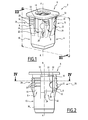
Figure 1 is a perspective view of an attachment device according to the invention; -
Figure 2 is a side view of the attachment device; -
Figure 3 is a sectional side view of the attachment device along III-III onFigure 1 ; -
Figure 4 is a sectional top view of the attachment device along IV-IV onFigure 2 ; and -
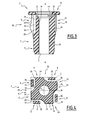
Figure 5 is a sectional side view of an assembly comprising a plate and the attachment device inserted through a hole in the plate before screwing a screw; and -
Figure 6 is a sectional side view of the assembly ofFigure 5 , after screwing a screw. - As illustrated on
Figure 1 - 4 , theattachment device 2 comprises anut member 4 extending along an axis A-A, a plate-shaped axialabutment flange member 6 extending transversely to the axis A-A andtabs 8 connecting thenut member 4 to theflange member 6. - The
attachment device 2 is for insertion of thenut member 4 into a hole extending though a plate with theflange member 6 axially abutting the plate and thetabs 8 axially engaging the underside of the plate to hold the attachment device captive in the hole. - The
attachment device 2 is molded in one piece. Thenut member 4, theflange 6 and the tabs are made in one piece of material. Theattachment device 2 is made in plastic material, for example in polyamide (PA), namely PA66. - The
nut member 4 comprises ahollow body 10 extending along the axis A-A and a thread-engaging bore 12 (Figure 3 ) extending within thebody 10 along axis A-A. Thebore 12 is a through bore and opens at both axial ends of thebody 10. Thebore 12 has a smooth internal surface. Thebore 12 is adapted such that a threaded shank forms an internal thread on the internal surface of thebore 12 at first screwing. - The
flange member 6 is spaced from thebody 10 along axis A-A. Theflange member 6 comprises an opening 14 coaxial to thebore 12. Theopening 14 has a diameter greater than that of thebore 12. Theflange member 6 has a lower face facing thebody 10 and an opposed upper face facing opposite thebody 10. - The
tabs 8 connect thebody 10 to theflange member 6. Eachtab 8 is elongated axially along axis A-A. Eachtab 8 has a first end connected to thebody 10 and a second end connected to theflange member 6. Thetabs 8 are distributed around thebody 10. - The first end of each
tab 8 is connected to a side surface of thebody 10 remote from the axial end of the body adjacent to theflange member 6. The second end of eachtab 8 is connected to the lower face of theflange member 6. - Each
tab 8 has afront face 16 facing outwardly and an oppositerear face 18 facing inwardly. - The
front face 16 of eachtab 8 is toothed. Thefront face 16 of each tab comprises a plurality ofteeth 20 distributed axially along thetab 8. Theteeth 20 have a varying height along thetab 8, more specifically an increasing height along thetab 8 from the second end of thetab 8 connected to theflange member 4 towards the first end of thetab 8 connected to thebody 10. - The
nut member 4 comprisesblocks 22. Eachblock 22 extends axially and has anabutment face 24 and alateral face 26. Theblocks 22 protrude radially outwardly form thebody 10 between thetabs 8. - As better seen on
Figure 4 , the abutment faces 24 of theblocks 22 are planar and define in section in a plane perpendicular to axis A-A a polygonal outline C withplanar side faces 28. Theattachment device 2 has here fourblocks 22 and the polygonal outline C is a square outline. - The
blocks 22 are anti-rotation members configured for preventing rotation of theattachment device 2 in the hole. Theblocks 22 are configured for their abutment faces 24 to abut the inner wall of a hole in which theattachment device 2 is inserted for preventing rotation of theattachment device 2. - The
lateral face 26 of eachblock 22 of aside face 28 faces towards therear face 18 of atab 8 of anotherside face 28. - The
blocks 22 define between themcavities 30 on theside faces 28. Eachcavity 30 extends axially. Each cavity is located at the corners of the polygonal outline C. Eachcavity 30 opens on the corresponding side face and also on theadjacent side face 28 defining the corresponding corner. Theblocks 22 impart to the nut member 4 a cross shaped cross-section with four branches. - Each
block 22 is offset laterally with respect to the radial axis which is normal to theabutment face 28 of theblock 22 and radial with respect to the axis A-A. Eachcavity 30 has a large opening on thecorresponding side face 28 and a small opening on theother side face 24 defining the corresponding corner with thecorresponding side face 28. - Each
tab 8 is positioned on arespective side face 28 extending along saidside face 28. Eachtab 8 extends alongside theabutment face 24 defining thecorresponding side face 28. Eachtab 8 is accommodated in arespective cavity 30. Thefront face 16 of eachtab 8 is substantially parallel to theabutment face 24 defining theside face 28. The plan of theside face 28 extends within the thickness of thetab 8, between thefront face 16 and therear face 18 of thetab 8. - The
attachment device 2 comprises on each side face 28 of the polygonal outline C atab 8 and ablock 22 extending alongside. - The
attachment device 2 comprises an axial gap between the axial proximal end of thebody 10 adjacent to theflange 8 and the lower face of theflange 8. - Each
block 22 comprises aprojection 32 extending theblock 22 beyond the axial proximal end of thebody 10. Theabutment face 24 extends on theprojection 32. Theprojection 32 is provided in the corner of theblock 22 at the junction of theabutment face 24 and thelateral face 26 of theblock 22. Theprojection 32 is in the form of a prong. - Each
block 22 is provided with arecess 33 in itslateral face 26 facing therear face 18 of atab 8. Therecess 33 opens on theabutment face 24 of thecorresponding block 22. Therecess 33 has a depth decreasing from theabutment face 24. Therecess 33 locally enlarges the gap between thelateral face 26 of ablock 22 and the facingrear face 18 of atab 8. - The
body 10 has aproximal section 34 adjacent theflange member 6 and adistal section 36 remote theflange member 6. Thedistal section 36 extends theproximal section 34 axially. The second ends of thetabs 8 are connected to thebody 10 at the junction between theproximal section 34 and thedistal section 36. - The
tabs 8 are distributed around theproximal section 34 and theblocks 22 protrude radially outwardly from theproximal section 34 between thetabs 8. - The
distal section 36 has a polygonal outline corresponding to that of the polygonal outline C defined by theblocks 22, but with slightly smaller dimensions. - The
distal section 36 is provided with sufficient length to accommodate the threaded shank of a screw. This prevents the screw from protruding from thebody 10. - As illustrated on
Figure 5 , anassembly 40 comprises afirst plate 42 having afirst hole 44 extending through thefirst plate 42 and theattachment device 2 inserted into thehole 44 and captive on thefirst plate 42. - The
nut member 4 extends through thehole 44 and theflange member 6 axially abuts the periphery of thehole 44 and prevents further insertion of theattachment device 2 in a first axial direction. Theteeth 20 of thetabs 8 engage the edge of thefirst hole 44 on the underside of thefirst plate 42 an prevent unintentional removal of theattachment device 2 in a second axial direction opposite the first axial direction. - The
first hole 44 has a cross section corresponding to the polygonal outline C defined by theblocks 22. The abutment faces 24 of theblocks 22 prevent rotation of theattachment device 2 with respect to thefirst hole 44. In case a torque is applied onto theattachment device 2, the abutment faces 24 abut the inner wall of thefirst hole 44 thus preventing rotation. - The
tabs 8 accommodated in thecavities 30 defined in the side faces 28 between theblocks 22 are prevented from being cut onto the edge of thefirst hole 44 due to a rotation of theattachment device 2, especially when thefirst plate 42 is a thin metal sheet with generally cutting edges. - As illustrated on
Figure 6 , asecond plate 46 having asecond hole 48 is laid upon thefirst plate 42 with thesecond hole 48 aligned with thefirst hole 44. Theflange member 6 is sandwiched between thefirst plate 42 and thesecond plate 46. - A
screw 50 having ascrew head 52 and a threadedshank 54 in screwed into thenut member 4 though thesecond hole 48 and theflange member 8. The threadedshank 54 is freely engaged thought thesecond hole 48 and theflange member 6. The threadedshank 54 is engaged in thebore 12 such that the thread of the threaded shank forms an internal thread into the internal surface of thebore 12 upon first screwing thescrew 50. - Upon tightening the
screw 50, thescrew 50 pulls thenut member 4 axially towards theflange member 6. Thescrew 50 is tightened until theprojections 32 of theblocks 22 abut theflange member 6 and theprojections 32 are compressed such that thenut member 4 axially abuts theflange member 6. - When the
nut member 4 is moved axially towards theflange member 6, thetabs 8 bend outwardly thus firmly engaging theteeth 20 with the edge of thefirst hole 44. Theattachment device 2 retains thefirst plate 42 with respect to thesecond plate 46. - The
attachment device 2 is locked into thefirst hole 44 simply by inserting thenut member 4 into thefirst hole 44 and thus engaging theteeth 20 on the edge of thefirst hole 44. Screwing of a screw further locks theattachment device 2 into thefirst hole 44 thus providing a reliable locking. - When engaging the screw into the
nut member 4, a torque is applied onto theattachment device 2. Theblocks 22 prevent rotation of thenut member 4 with respect to thefirst hole 44 with protecting thetabs 8 from being cut by the edge of thefirst plate 42 delimiting thefirst hole 44. Locking thenut member 4 in rotation further allows forming an internal thread of good geometry in the internal surface of thebore 12 at first screwing. - The
attachment device 2 is adapted for locking on plates of different thicknesses. Thetoothed tabs 8 allow locking in hole of plates of different thicknesses. - Plates may have a small thickness, smaller that the height of the axial gap between the
body 10 and theflange member 6. Theprojections 32 account for such plates of small thickness, by providing an extra length to the abutment faces 24 towards theflange member 8, while being compressible to allow thebody 10 to move and abut theflange 8 upon tightening a screw therein. - A reliable locking of the
attachment device 2 is obtained with a small axial stroke of thenut member 4. Thenut member 4 can be provided with sufficient length for accommodating screws without the screw protruding from thenut member 4 after tightening. This protects the operator from injury and protects other parts of the vehicle from damage during mounting operations. - The
attachment device 2 is adapted for accommodating screws of different types, with different external threads. - The
attachment device 2 is moulded in one piece of material, preferably of plastic material, e.g. polyamide (PA). - The
attachment device 2 is obtained for example in a mould with slides. The gaps between eachtab 8 and the twoadjacent blocks 22 are formed with slides. The slides are thin for generating thin gaps, namely between eachtab 8 and theblock 22 facing therear face 18 of thetab 8. Thin slides are fragile. Therecesses 33 provided in theblocks 22 form passages allowing accommodating reinforcements of the slides. It is thus possible to manufacture the attachment device economically and reliably.
Claims (10)
- Attachment device comprising:a nut member (4) extending along an axis (A-A) and having an axial thread-engaging bore (12),a flange member (6) extending transversely to the axis (A-A) and having an opening (14), the flange member (6) being spaced axially from nut member (4),tabs (8) connecting the flange member (6) to the nut member (4), each tab (8) having a first end connected to the nut member (4) and a second end connected to the flange (6),wherein the nut member (4) comprises blocks (22) having abutment faces (24) defining a polygonal outline (C) with side faces (28), each tab (8) extending alongside an abutment face (24) on a side face (28).
- Attachment device according to claim 1, comprising a tab (8) on each side face (28).
- Attachment device according to claim 1 or 2, wherein the abutment faces (28) define a square outline with four side faces (28).
- Attachment device according to any preceding claim, wherein each tab (8) is accommodated in a cavity defined in a side face (28).
- Attachment device according to any preceding claim, wherein each block (22) has a lateral face (26) facing a tab (8), said lateral face (26) having a recess (33).
- Attachment device according to any preceding claim, comprising a gap between an axial end of a body (10) of the nut member (4) having the bore (12) extending therein, each block (22) having a protrusion (32) protruding axially towards the flange member (6) beyond the axial end of the body (10), the abutment face (24) of the block (22) extending on said protrusion (32).
- Attachment device according to any preceding claim, wherein the bore (12) has a length for accommodating a threaded shank of a screw screwed in the nut member (4) through the opening (14) of the flange member (6) without the threaded shank protruding from the axial end of the nut member (4) opposite the flange member (6).
- Attachment device according to any preceding claim, wherein each tab (8) has a toothed front face (16) facing outwardly.
- Attachment device according to claim 8, wherein each tab (8) comprises teeth (20) of increasing height along the tab (8).
- Assembly comprises a plate (42) comprising a hole (44) and an attachment device (2) as in any preceding claim inserted and held captive into the hole (44), the hole (44) having a section corresponding to the polygonal outline (C) defined by the abutment faces (24) of the blocks.
Priority Applications (5)
| Application Number | Priority Date | Filing Date | Title |
|---|---|---|---|
| ES11175258.0T ES2623527T3 (en) | 2011-07-25 | 2011-07-25 | Fixing device for fixing on a plate having a hole and assembly comprising said fixing device |
| PL11175258T PL2551531T3 (en) | 2011-07-25 | 2011-07-25 | Attachment device for fixing on a plate having a hole and assembly comprising such an attachment device |
| EP11175258.0A EP2551531B1 (en) | 2011-07-25 | 2011-07-25 | Attachment device for fixing on a plate having a hole and assembly comprising such an attachment device |
| US13/557,677 US8939690B2 (en) | 2011-07-25 | 2012-07-25 | Attachment device for fixing on a plate having a hole and assembly comprising such an attachment device |
| CN2012203641422U CN202768597U (en) | 2011-07-25 | 2012-07-25 | Connection device and assembly including connection device |
Applications Claiming Priority (1)
| Application Number | Priority Date | Filing Date | Title |
|---|---|---|---|
| EP11175258.0A EP2551531B1 (en) | 2011-07-25 | 2011-07-25 | Attachment device for fixing on a plate having a hole and assembly comprising such an attachment device |
Publications (2)
| Publication Number | Publication Date |
|---|---|
| EP2551531A1 true EP2551531A1 (en) | 2013-01-30 |
| EP2551531B1 EP2551531B1 (en) | 2017-03-22 |
Family
ID=44510767
Family Applications (1)
| Application Number | Title | Priority Date | Filing Date |
|---|---|---|---|
| EP11175258.0A Active EP2551531B1 (en) | 2011-07-25 | 2011-07-25 | Attachment device for fixing on a plate having a hole and assembly comprising such an attachment device |
Country Status (5)
| Country | Link |
|---|---|
| US (1) | US8939690B2 (en) |
| EP (1) | EP2551531B1 (en) |
| CN (1) | CN202768597U (en) |
| ES (1) | ES2623527T3 (en) |
| PL (1) | PL2551531T3 (en) |
Families Citing this family (7)
| Publication number | Priority date | Publication date | Assignee | Title |
|---|---|---|---|---|
| ES2356761B1 (en) * | 2009-07-31 | 2012-02-29 | Illinois Tools Works Inc. | ROOF CLIP FOR FIXING ACCESSORIES TO VEH� CULOS PANELS. |
| US9506495B2 (en) * | 2013-06-21 | 2016-11-29 | Steering Solutions Ip Holding Corporation | Self-locking insert |
| KR20170040544A (en) * | 2015-10-05 | 2017-04-13 | 삼성전자주식회사 | Inner case for refrigerator and manufacturing method of the same |
| US10260546B2 (en) * | 2016-07-07 | 2019-04-16 | Ford Global Technologies, Llc | Insert nut and fastening system with integral seal and bumper |
| US11629742B2 (en) * | 2018-06-19 | 2023-04-18 | Illinois Tool Works Inc. | Box nut retainer |
| PL3995709T3 (en) | 2020-11-10 | 2024-02-05 | Celulosa Fabril, S.A. | Attachment device |
| USD977959S1 (en) * | 2021-03-19 | 2023-02-14 | Piotr Konopka | Binding element |
Citations (3)
| Publication number | Priority date | Publication date | Assignee | Title |
|---|---|---|---|---|
| US4082030A (en) * | 1977-03-25 | 1978-04-04 | Illinois Tool Works, Inc. | Plastic screw grommet |
| EP1367721A1 (en) | 2001-03-07 | 2003-12-03 | Sakai, Yasue | Interpolating function generating apparatus and method, digital-analog converter, data interpolator, program, and record medium |
| FR2861818A1 (en) * | 2003-11-04 | 2005-05-06 | Piolax Inc | Sleeve for screw, has projection that is inclined towards base in direction in which screwing unit is screwed, and projection that maintains pressure contact with internal periphery surface of assembling hole of vehicle panel |
Family Cites Families (12)
| Publication number | Priority date | Publication date | Assignee | Title |
|---|---|---|---|---|
| US3143916A (en) * | 1962-04-03 | 1964-08-11 | A A Rice Inc | Collapsible self-anchoring device |
| US3601869A (en) * | 1963-05-29 | 1971-08-31 | Eaton Yale & Towne | Fasteners |
| US3313083A (en) * | 1963-05-29 | 1967-04-11 | Tinnerman Products Inc | Deformable plastic fastener |
| US4089248A (en) * | 1975-05-21 | 1978-05-16 | National Molding Corporation | Self-locking unitary molded plastic fastener |
| JPS5514359A (en) * | 1978-07-18 | 1980-01-31 | Nifco Inc | Panel fitting instrument |
| JPS56127067A (en) * | 1980-03-12 | 1981-10-05 | Ietatsu Ono | Calcium capsule |
| US5078561A (en) * | 1990-11-08 | 1992-01-07 | Illinois Tools Works, Inc. | Plastic expansion nut |
| US5173025A (en) * | 1991-12-26 | 1992-12-22 | Nifco Inc. | Screw grommet having a secured internal thread member |
| JPH0625614U (en) * | 1992-09-04 | 1994-04-08 | ポップリベット・ファスナー株式会社 | Screw grommet device |
| JP2001289215A (en) * | 2000-04-03 | 2001-10-19 | Aoyama Seisakusho Co Ltd | Waterproof grommet |
| DE10223747B4 (en) | 2002-05-28 | 2007-09-06 | Dieter Dr. Grotmann | Clamping piece for mounting a component to a plate |
| DE10305610A1 (en) * | 2003-02-11 | 2004-08-19 | Ejot Gmbh & Co. Kg | Plastic nut for mounting on a component with a breakthrough |
-
2011
- 2011-07-25 EP EP11175258.0A patent/EP2551531B1/en active Active
- 2011-07-25 ES ES11175258.0T patent/ES2623527T3/en active Active
- 2011-07-25 PL PL11175258T patent/PL2551531T3/en unknown
-
2012
- 2012-07-25 CN CN2012203641422U patent/CN202768597U/en not_active Expired - Lifetime
- 2012-07-25 US US13/557,677 patent/US8939690B2/en active Active
Patent Citations (3)
| Publication number | Priority date | Publication date | Assignee | Title |
|---|---|---|---|---|
| US4082030A (en) * | 1977-03-25 | 1978-04-04 | Illinois Tool Works, Inc. | Plastic screw grommet |
| EP1367721A1 (en) | 2001-03-07 | 2003-12-03 | Sakai, Yasue | Interpolating function generating apparatus and method, digital-analog converter, data interpolator, program, and record medium |
| FR2861818A1 (en) * | 2003-11-04 | 2005-05-06 | Piolax Inc | Sleeve for screw, has projection that is inclined towards base in direction in which screwing unit is screwed, and projection that maintains pressure contact with internal periphery surface of assembling hole of vehicle panel |
Also Published As
| Publication number | Publication date |
|---|---|
| CN202768597U (en) | 2013-03-06 |
| EP2551531B1 (en) | 2017-03-22 |
| US20130101370A1 (en) | 2013-04-25 |
| PL2551531T3 (en) | 2017-09-29 |
| ES2623527T3 (en) | 2017-07-11 |
| US8939690B2 (en) | 2015-01-27 |
Similar Documents
| Publication | Publication Date | Title |
|---|---|---|
| EP2551531B1 (en) | Attachment device for fixing on a plate having a hole and assembly comprising such an attachment device | |
| AU2016303475B2 (en) | Threaded fastener | |
| US5551817A (en) | Fastener for attaching in one direction | |
| US7959392B2 (en) | U-nut fastener assembly | |
| US20120230798A1 (en) | Locking fastener | |
| US20080240883A1 (en) | Threaded Insert and Method of Using Same | |
| WO2014146187A1 (en) | Fastener head and complementary driver | |
| US20160327079A1 (en) | Bracket for securing a structural member | |
| MX2010007702A (en) | Connecting device and method for creating a screw connection. | |
| JPH0541844B2 (en) | ||
| CN103403366A (en) | A procedure for panel assembly and device associated thereto | |
| US9180564B2 (en) | Device for securing a cap screw to an element that is to be attached to another element | |
| JP6779568B2 (en) | Tightening torque control tool, nuts and bolts with tightening torque control tool, and mounting method of attachments | |
| US20210071708A1 (en) | Ball pin | |
| EP2492523B1 (en) | Anti-vibration bolt | |
| EP3469220B1 (en) | Bolt with safety device for a bolt head and a method for releasing the bolt | |
| US20210040969A1 (en) | Adjustable potted insert | |
| DE102014104597A1 (en) | fastener | |
| JP2017106603A (en) | Fastening structure | |
| US20190264725A1 (en) | Removable push-on fastener | |
| US6683257B1 (en) | Attachment clip | |
| US20150226251A1 (en) | Assembly having two components coupled with fastening member | |
| JP6395450B2 (en) | Opening frame forming frame member | |
| KR200388166Y1 (en) | Screw for preventing loosening | |
| DE102015216368A1 (en) | Connecting device for a component carrier |
Legal Events
| Date | Code | Title | Description |
|---|---|---|---|
| PUAI | Public reference made under article 153(3) epc to a published international application that has entered the european phase |
Free format text: ORIGINAL CODE: 0009012 |
|
| AK | Designated contracting states |
Kind code of ref document: A1 Designated state(s): AL AT BE BG CH CY CZ DE DK EE ES FI FR GB GR HR HU IE IS IT LI LT LU LV MC MK MT NL NO PL PT RO RS SE SI SK SM TR |
|
| AX | Request for extension of the european patent |
Extension state: BA ME |
|
| 17P | Request for examination filed |
Effective date: 20130701 |
|
| RBV | Designated contracting states (corrected) |
Designated state(s): AL AT BE BG CH CY CZ DE DK EE ES FI FR GB GR HR HU IE IS IT LI LT LU LV MC MK MT NL NO PL PT RO RS SE SI SK SM TR |
|
| RAP1 | Party data changed (applicant data changed or rights of an application transferred) |
Owner name: TRW AUTOMOTIVE ELECTRONICS & COMPONENTS GMBH Owner name: FAURECIA INTERIEUR INDUSTRIE |
|
| REG | Reference to a national code |
Ref country code: DE Ref legal event code: R079 Ref document number: 602011036143 Country of ref document: DE Free format text: PREVIOUS MAIN CLASS: F16B0005020000 Ipc: F16B0037040000 |
|
| RIC1 | Information provided on ipc code assigned before grant |
Ipc: F16B 37/04 20060101AFI20160620BHEP Ipc: F16B 37/00 20060101ALI20160620BHEP |
|
| GRAP | Despatch of communication of intention to grant a patent |
Free format text: ORIGINAL CODE: EPIDOSNIGR1 |
|
| INTG | Intention to grant announced |
Effective date: 20160801 |
|
| GRAS | Grant fee paid |
Free format text: ORIGINAL CODE: EPIDOSNIGR3 |
|
| RAP1 | Party data changed (applicant data changed or rights of an application transferred) |
Owner name: ITW FASTENER PRODUCTS GMBH Owner name: FAURECIA INTERIEUR INDUSTRIE |
|
| GRAA | (expected) grant |
Free format text: ORIGINAL CODE: 0009210 |
|
| AK | Designated contracting states |
Kind code of ref document: B1 Designated state(s): AL AT BE BG CH CY CZ DE DK EE ES FI FR GB GR HR HU IE IS IT LI LT LU LV MC MK MT NL NO PL PT RO RS SE SI SK SM TR |
|
| REG | Reference to a national code |
Ref country code: GB Ref legal event code: FG4D |
|
| REG | Reference to a national code |
Ref country code: CH Ref legal event code: EP |
|
| REG | Reference to a national code |
Ref country code: AT Ref legal event code: REF Ref document number: 878092 Country of ref document: AT Kind code of ref document: T Effective date: 20170415 |
|
| REG | Reference to a national code |
Ref country code: IE Ref legal event code: FG4D |
|
| REG | Reference to a national code |
Ref country code: DE Ref legal event code: R096 Ref document number: 602011036143 Country of ref document: DE |
|
| REG | Reference to a national code |
Ref country code: RO Ref legal event code: EPE |
|
| REG | Reference to a national code |
Ref country code: FR Ref legal event code: PLFP Year of fee payment: 7 |
|
| RAP2 | Party data changed (patent owner data changed or rights of a patent transferred) |
Owner name: FAURECIA INTERIEUR INDUSTRIE Owner name: ILLINOIS TOOL WORKS INC. |
|
| REG | Reference to a national code |
Ref country code: ES Ref legal event code: FG2A Ref document number: 2623527 Country of ref document: ES Kind code of ref document: T3 Effective date: 20170711 |
|
| REG | Reference to a national code |
Ref country code: NL Ref legal event code: MP Effective date: 20170322 |
|
| PG25 | Lapsed in a contracting state [announced via postgrant information from national office to epo] |
Ref country code: HR Free format text: LAPSE BECAUSE OF FAILURE TO SUBMIT A TRANSLATION OF THE DESCRIPTION OR TO PAY THE FEE WITHIN THE PRESCRIBED TIME-LIMIT Effective date: 20170322 Ref country code: GR Free format text: LAPSE BECAUSE OF FAILURE TO SUBMIT A TRANSLATION OF THE DESCRIPTION OR TO PAY THE FEE WITHIN THE PRESCRIBED TIME-LIMIT Effective date: 20170623 Ref country code: FI Free format text: LAPSE BECAUSE OF FAILURE TO SUBMIT A TRANSLATION OF THE DESCRIPTION OR TO PAY THE FEE WITHIN THE PRESCRIBED TIME-LIMIT Effective date: 20170322 Ref country code: NO Free format text: LAPSE BECAUSE OF FAILURE TO SUBMIT A TRANSLATION OF THE DESCRIPTION OR TO PAY THE FEE WITHIN THE PRESCRIBED TIME-LIMIT Effective date: 20170622 Ref country code: LT Free format text: LAPSE BECAUSE OF FAILURE TO SUBMIT A TRANSLATION OF THE DESCRIPTION OR TO PAY THE FEE WITHIN THE PRESCRIBED TIME-LIMIT Effective date: 20170322 |
|
| REG | Reference to a national code |
Ref country code: LT Ref legal event code: MG4D |
|
| REG | Reference to a national code |
Ref country code: AT Ref legal event code: MK05 Ref document number: 878092 Country of ref document: AT Kind code of ref document: T Effective date: 20170322 |
|
| PG25 | Lapsed in a contracting state [announced via postgrant information from national office to epo] |
Ref country code: RS Free format text: LAPSE BECAUSE OF FAILURE TO SUBMIT A TRANSLATION OF THE DESCRIPTION OR TO PAY THE FEE WITHIN THE PRESCRIBED TIME-LIMIT Effective date: 20170322 Ref country code: LV Free format text: LAPSE BECAUSE OF FAILURE TO SUBMIT A TRANSLATION OF THE DESCRIPTION OR TO PAY THE FEE WITHIN THE PRESCRIBED TIME-LIMIT Effective date: 20170322 Ref country code: BG Free format text: LAPSE BECAUSE OF FAILURE TO SUBMIT A TRANSLATION OF THE DESCRIPTION OR TO PAY THE FEE WITHIN THE PRESCRIBED TIME-LIMIT Effective date: 20170622 Ref country code: SE Free format text: LAPSE BECAUSE OF FAILURE TO SUBMIT A TRANSLATION OF THE DESCRIPTION OR TO PAY THE FEE WITHIN THE PRESCRIBED TIME-LIMIT Effective date: 20170322 |
|
| PG25 | Lapsed in a contracting state [announced via postgrant information from national office to epo] |
Ref country code: NL Free format text: LAPSE BECAUSE OF FAILURE TO SUBMIT A TRANSLATION OF THE DESCRIPTION OR TO PAY THE FEE WITHIN THE PRESCRIBED TIME-LIMIT Effective date: 20170322 |
|
| PG25 | Lapsed in a contracting state [announced via postgrant information from national office to epo] |
Ref country code: CZ Free format text: LAPSE BECAUSE OF FAILURE TO SUBMIT A TRANSLATION OF THE DESCRIPTION OR TO PAY THE FEE WITHIN THE PRESCRIBED TIME-LIMIT Effective date: 20170322 Ref country code: AT Free format text: LAPSE BECAUSE OF FAILURE TO SUBMIT A TRANSLATION OF THE DESCRIPTION OR TO PAY THE FEE WITHIN THE PRESCRIBED TIME-LIMIT Effective date: 20170322 Ref country code: SK Free format text: LAPSE BECAUSE OF FAILURE TO SUBMIT A TRANSLATION OF THE DESCRIPTION OR TO PAY THE FEE WITHIN THE PRESCRIBED TIME-LIMIT Effective date: 20170322 Ref country code: EE Free format text: LAPSE BECAUSE OF FAILURE TO SUBMIT A TRANSLATION OF THE DESCRIPTION OR TO PAY THE FEE WITHIN THE PRESCRIBED TIME-LIMIT Effective date: 20170322 |
|
| PG25 | Lapsed in a contracting state [announced via postgrant information from national office to epo] |
Ref country code: SM Free format text: LAPSE BECAUSE OF FAILURE TO SUBMIT A TRANSLATION OF THE DESCRIPTION OR TO PAY THE FEE WITHIN THE PRESCRIBED TIME-LIMIT Effective date: 20170322 Ref country code: PT Free format text: LAPSE BECAUSE OF FAILURE TO SUBMIT A TRANSLATION OF THE DESCRIPTION OR TO PAY THE FEE WITHIN THE PRESCRIBED TIME-LIMIT Effective date: 20170724 Ref country code: IS Free format text: LAPSE BECAUSE OF FAILURE TO SUBMIT A TRANSLATION OF THE DESCRIPTION OR TO PAY THE FEE WITHIN THE PRESCRIBED TIME-LIMIT Effective date: 20170722 |
|
| REG | Reference to a national code |
Ref country code: DE Ref legal event code: R097 Ref document number: 602011036143 Country of ref document: DE |
|
| PLBE | No opposition filed within time limit |
Free format text: ORIGINAL CODE: 0009261 |
|
| STAA | Information on the status of an ep patent application or granted ep patent |
Free format text: STATUS: NO OPPOSITION FILED WITHIN TIME LIMIT |
|
| PG25 | Lapsed in a contracting state [announced via postgrant information from national office to epo] |
Ref country code: DK Free format text: LAPSE BECAUSE OF FAILURE TO SUBMIT A TRANSLATION OF THE DESCRIPTION OR TO PAY THE FEE WITHIN THE PRESCRIBED TIME-LIMIT Effective date: 20170322 |
|
| 26N | No opposition filed |
Effective date: 20180102 |
|
| PG25 | Lapsed in a contracting state [announced via postgrant information from national office to epo] |
Ref country code: SI Free format text: LAPSE BECAUSE OF FAILURE TO SUBMIT A TRANSLATION OF THE DESCRIPTION OR TO PAY THE FEE WITHIN THE PRESCRIBED TIME-LIMIT Effective date: 20170322 |
|
| REG | Reference to a national code |
Ref country code: CH Ref legal event code: PL |
|
| REG | Reference to a national code |
Ref country code: IE Ref legal event code: MM4A |
|
| PG25 | Lapsed in a contracting state [announced via postgrant information from national office to epo] |
Ref country code: CH Free format text: LAPSE BECAUSE OF NON-PAYMENT OF DUE FEES Effective date: 20170731 Ref country code: IE Free format text: LAPSE BECAUSE OF NON-PAYMENT OF DUE FEES Effective date: 20170725 Ref country code: LI Free format text: LAPSE BECAUSE OF NON-PAYMENT OF DUE FEES Effective date: 20170731 |
|
| REG | Reference to a national code |
Ref country code: BE Ref legal event code: MM Effective date: 20170731 |
|
| REG | Reference to a national code |
Ref country code: FR Ref legal event code: PLFP Year of fee payment: 8 |
|
| PG25 | Lapsed in a contracting state [announced via postgrant information from national office to epo] |
Ref country code: LU Free format text: LAPSE BECAUSE OF NON-PAYMENT OF DUE FEES Effective date: 20170725 |
|
| PG25 | Lapsed in a contracting state [announced via postgrant information from national office to epo] |
Ref country code: BE Free format text: LAPSE BECAUSE OF NON-PAYMENT OF DUE FEES Effective date: 20170731 |
|
| PG25 | Lapsed in a contracting state [announced via postgrant information from national office to epo] |
Ref country code: MT Free format text: LAPSE BECAUSE OF NON-PAYMENT OF DUE FEES Effective date: 20170725 |
|
| PG25 | Lapsed in a contracting state [announced via postgrant information from national office to epo] |
Ref country code: MC Free format text: LAPSE BECAUSE OF FAILURE TO SUBMIT A TRANSLATION OF THE DESCRIPTION OR TO PAY THE FEE WITHIN THE PRESCRIBED TIME-LIMIT Effective date: 20170322 Ref country code: HU Free format text: LAPSE BECAUSE OF FAILURE TO SUBMIT A TRANSLATION OF THE DESCRIPTION OR TO PAY THE FEE WITHIN THE PRESCRIBED TIME-LIMIT; INVALID AB INITIO Effective date: 20110725 |
|
| PG25 | Lapsed in a contracting state [announced via postgrant information from national office to epo] |
Ref country code: CY Free format text: LAPSE BECAUSE OF NON-PAYMENT OF DUE FEES Effective date: 20170322 |
|
| PG25 | Lapsed in a contracting state [announced via postgrant information from national office to epo] |
Ref country code: MK Free format text: LAPSE BECAUSE OF FAILURE TO SUBMIT A TRANSLATION OF THE DESCRIPTION OR TO PAY THE FEE WITHIN THE PRESCRIBED TIME-LIMIT Effective date: 20170322 |
|
| PG25 | Lapsed in a contracting state [announced via postgrant information from national office to epo] |
Ref country code: AL Free format text: LAPSE BECAUSE OF FAILURE TO SUBMIT A TRANSLATION OF THE DESCRIPTION OR TO PAY THE FEE WITHIN THE PRESCRIBED TIME-LIMIT Effective date: 20170322 |
|
| PGFP | Annual fee paid to national office [announced via postgrant information from national office to epo] |
Ref country code: IT Payment date: 20230620 Year of fee payment: 13 Ref country code: FR Payment date: 20230621 Year of fee payment: 13 |
|
| PGFP | Annual fee paid to national office [announced via postgrant information from national office to epo] |
Ref country code: TR Payment date: 20230626 Year of fee payment: 13 Ref country code: PL Payment date: 20230621 Year of fee payment: 13 |
|
| PGFP | Annual fee paid to national office [announced via postgrant information from national office to epo] |
Ref country code: RO Payment date: 20230720 Year of fee payment: 13 Ref country code: GB Payment date: 20230620 Year of fee payment: 13 Ref country code: ES Payment date: 20230801 Year of fee payment: 13 |
|
| PGFP | Annual fee paid to national office [announced via postgrant information from national office to epo] |
Ref country code: DE Payment date: 20230620 Year of fee payment: 13 |