EP1367391A1 - Method and apparatus for determining oxygen in a metal - Google Patents
Method and apparatus for determining oxygen in a metal Download PDFInfo
- Publication number
- EP1367391A1 EP1367391A1 EP03012040A EP03012040A EP1367391A1 EP 1367391 A1 EP1367391 A1 EP 1367391A1 EP 03012040 A EP03012040 A EP 03012040A EP 03012040 A EP03012040 A EP 03012040A EP 1367391 A1 EP1367391 A1 EP 1367391A1
- Authority
- EP
- European Patent Office
- Prior art keywords
- sample
- measured
- graphite crucible
- analyzing
- oxygen
- Prior art date
- Legal status (The legal status is an assumption and is not a legal conclusion. Google has not performed a legal analysis and makes no representation as to the accuracy of the status listed.)
- Withdrawn
Links
- QVGXLLKOCUKJST-UHFFFAOYSA-N atomic oxygen Chemical compound [O] QVGXLLKOCUKJST-UHFFFAOYSA-N 0.000 title claims description 154
- 239000001301 oxygen Substances 0.000 title claims description 154
- 229910052760 oxygen Inorganic materials 0.000 title claims description 154
- 229910052751 metal Inorganic materials 0.000 title claims description 69
- 239000002184 metal Substances 0.000 title claims description 69
- 238000000034 method Methods 0.000 title claims description 29
- OKTJSMMVPCPJKN-UHFFFAOYSA-N Carbon Chemical compound [C] OKTJSMMVPCPJKN-UHFFFAOYSA-N 0.000 claims description 146
- 229910002804 graphite Inorganic materials 0.000 claims description 140
- 239000010439 graphite Substances 0.000 claims description 140
- 239000007789 gas Substances 0.000 claims description 75
- 230000004907 flux Effects 0.000 claims description 66
- 229910000831 Steel Inorganic materials 0.000 claims description 53
- 239000010959 steel Substances 0.000 claims description 53
- 238000010438 heat treatment Methods 0.000 claims description 51
- 239000012080 ambient air Substances 0.000 claims description 48
- 230000005291 magnetic effect Effects 0.000 claims description 45
- 239000011261 inert gas Substances 0.000 claims description 33
- 230000033001 locomotion Effects 0.000 claims description 21
- 238000002844 melting Methods 0.000 claims description 20
- 230000008018 melting Effects 0.000 claims description 20
- 238000004891 communication Methods 0.000 claims description 13
- 230000009467 reduction Effects 0.000 claims description 13
- 239000000835 fiber Substances 0.000 claims description 11
- 238000009835 boiling Methods 0.000 claims description 8
- 230000006698 induction Effects 0.000 claims description 4
- 238000001179 sorption measurement Methods 0.000 claims description 4
- 230000002401 inhibitory effect Effects 0.000 claims description 3
- 239000010408 film Substances 0.000 description 43
- UGFAIRIUMAVXCW-UHFFFAOYSA-N Carbon monoxide Chemical compound [O+]#[C-] UGFAIRIUMAVXCW-UHFFFAOYSA-N 0.000 description 28
- 229910002091 carbon monoxide Inorganic materials 0.000 description 28
- 239000001307 helium Substances 0.000 description 22
- 229910052734 helium Inorganic materials 0.000 description 22
- SWQJXJOGLNCZEY-UHFFFAOYSA-N helium atom Chemical compound [He] SWQJXJOGLNCZEY-UHFFFAOYSA-N 0.000 description 22
- 238000004458 analytical method Methods 0.000 description 11
- 238000005259 measurement Methods 0.000 description 8
- ATJFFYVFTNAWJD-UHFFFAOYSA-N Tin Chemical compound [Sn] ATJFFYVFTNAWJD-UHFFFAOYSA-N 0.000 description 7
- 230000008859 change Effects 0.000 description 7
- 229910052799 carbon Inorganic materials 0.000 description 6
- XKRFYHLGVUSROY-UHFFFAOYSA-N Argon Chemical compound [Ar] XKRFYHLGVUSROY-UHFFFAOYSA-N 0.000 description 4
- 238000007872 degassing Methods 0.000 description 4
- 230000005294 ferromagnetic effect Effects 0.000 description 4
- 230000001105 regulatory effect Effects 0.000 description 4
- 238000010301 surface-oxidation reaction Methods 0.000 description 4
- 238000004519 manufacturing process Methods 0.000 description 3
- 239000000463 material Substances 0.000 description 3
- 238000010926 purge Methods 0.000 description 3
- 238000012546 transfer Methods 0.000 description 3
- CURLTUGMZLYLDI-UHFFFAOYSA-N Carbon dioxide Chemical compound O=C=O CURLTUGMZLYLDI-UHFFFAOYSA-N 0.000 description 2
- 238000005033 Fourier transform infrared spectroscopy Methods 0.000 description 2
- 229910052786 argon Inorganic materials 0.000 description 2
- 239000000498 cooling water Substances 0.000 description 2
- 239000006185 dispersion Substances 0.000 description 2
- 238000000605 extraction Methods 0.000 description 2
- 230000004927 fusion Effects 0.000 description 2
- JEIPFZHSYJVQDO-UHFFFAOYSA-N iron(III) oxide Inorganic materials O=[Fe]O[Fe]=O JEIPFZHSYJVQDO-UHFFFAOYSA-N 0.000 description 2
- 230000005389 magnetism Effects 0.000 description 2
- 238000012986 modification Methods 0.000 description 2
- 230000004048 modification Effects 0.000 description 2
- 238000001745 non-dispersive infrared spectroscopy Methods 0.000 description 2
- 238000007254 oxidation reaction Methods 0.000 description 2
- 230000002093 peripheral effect Effects 0.000 description 2
- 239000000843 powder Substances 0.000 description 2
- RYGMFSIKBFXOCR-UHFFFAOYSA-N Copper Chemical compound [Cu] RYGMFSIKBFXOCR-UHFFFAOYSA-N 0.000 description 1
- UFHFLCQGNIYNRP-UHFFFAOYSA-N Hydrogen Chemical compound [H][H] UFHFLCQGNIYNRP-UHFFFAOYSA-N 0.000 description 1
- 230000015572 biosynthetic process Effects 0.000 description 1
- 229910002092 carbon dioxide Inorganic materials 0.000 description 1
- 239000001569 carbon dioxide Substances 0.000 description 1
- 238000010276 construction Methods 0.000 description 1
- 230000001276 controlling effect Effects 0.000 description 1
- 229910052802 copper Inorganic materials 0.000 description 1
- 239000010949 copper Substances 0.000 description 1
- 230000003247 decreasing effect Effects 0.000 description 1
- 238000007599 discharging Methods 0.000 description 1
- 230000000694 effects Effects 0.000 description 1
- 230000005484 gravity Effects 0.000 description 1
- 239000001257 hydrogen Substances 0.000 description 1
- 229910052739 hydrogen Inorganic materials 0.000 description 1
- 238000013208 measuring procedure Methods 0.000 description 1
- 230000003647 oxidation Effects 0.000 description 1
- 238000003825 pressing Methods 0.000 description 1
- 230000008569 process Effects 0.000 description 1
- 239000002904 solvent Substances 0.000 description 1
- 238000005728 strengthening Methods 0.000 description 1
- 239000002344 surface layer Substances 0.000 description 1
- 239000010409 thin film Substances 0.000 description 1
Images







Classifications
-
- G—PHYSICS
- G01—MEASURING; TESTING
- G01N—INVESTIGATING OR ANALYSING MATERIALS BY DETERMINING THEIR CHEMICAL OR PHYSICAL PROPERTIES
- G01N33/00—Investigating or analysing materials by specific methods not covered by groups G01N1/00 - G01N31/00
- G01N33/20—Metals
- G01N33/202—Constituents thereof
- G01N33/2022—Non-metallic constituents
- G01N33/2025—Gaseous constituents
-
- Y—GENERAL TAGGING OF NEW TECHNOLOGICAL DEVELOPMENTS; GENERAL TAGGING OF CROSS-SECTIONAL TECHNOLOGIES SPANNING OVER SEVERAL SECTIONS OF THE IPC; TECHNICAL SUBJECTS COVERED BY FORMER USPC CROSS-REFERENCE ART COLLECTIONS [XRACs] AND DIGESTS
- Y10—TECHNICAL SUBJECTS COVERED BY FORMER USPC
- Y10T—TECHNICAL SUBJECTS COVERED BY FORMER US CLASSIFICATION
- Y10T436/00—Chemistry: analytical and immunological testing
- Y10T436/11—Automated chemical analysis
-
- Y—GENERAL TAGGING OF NEW TECHNOLOGICAL DEVELOPMENTS; GENERAL TAGGING OF CROSS-SECTIONAL TECHNOLOGIES SPANNING OVER SEVERAL SECTIONS OF THE IPC; TECHNICAL SUBJECTS COVERED BY FORMER USPC CROSS-REFERENCE ART COLLECTIONS [XRACs] AND DIGESTS
- Y10—TECHNICAL SUBJECTS COVERED BY FORMER USPC
- Y10T—TECHNICAL SUBJECTS COVERED BY FORMER US CLASSIFICATION
- Y10T436/00—Chemistry: analytical and immunological testing
- Y10T436/20—Oxygen containing
-
- Y—GENERAL TAGGING OF NEW TECHNOLOGICAL DEVELOPMENTS; GENERAL TAGGING OF CROSS-SECTIONAL TECHNOLOGIES SPANNING OVER SEVERAL SECTIONS OF THE IPC; TECHNICAL SUBJECTS COVERED BY FORMER USPC CROSS-REFERENCE ART COLLECTIONS [XRACs] AND DIGESTS
- Y10—TECHNICAL SUBJECTS COVERED BY FORMER USPC
- Y10T—TECHNICAL SUBJECTS COVERED BY FORMER US CLASSIFICATION
- Y10T436/00—Chemistry: analytical and immunological testing
- Y10T436/20—Oxygen containing
- Y10T436/207497—Molecular oxygen
- Y10T436/209163—Dissolved or trace oxygen or oxygen content of a sealed environment
-
- Y—GENERAL TAGGING OF NEW TECHNOLOGICAL DEVELOPMENTS; GENERAL TAGGING OF CROSS-SECTIONAL TECHNOLOGIES SPANNING OVER SEVERAL SECTIONS OF THE IPC; TECHNICAL SUBJECTS COVERED BY FORMER USPC CROSS-REFERENCE ART COLLECTIONS [XRACs] AND DIGESTS
- Y10—TECHNICAL SUBJECTS COVERED BY FORMER USPC
- Y10T—TECHNICAL SUBJECTS COVERED BY FORMER US CLASSIFICATION
- Y10T436/00—Chemistry: analytical and immunological testing
- Y10T436/25—Chemistry: analytical and immunological testing including sample preparation
-
- Y—GENERAL TAGGING OF NEW TECHNOLOGICAL DEVELOPMENTS; GENERAL TAGGING OF CROSS-SECTIONAL TECHNOLOGIES SPANNING OVER SEVERAL SECTIONS OF THE IPC; TECHNICAL SUBJECTS COVERED BY FORMER USPC CROSS-REFERENCE ART COLLECTIONS [XRACs] AND DIGESTS
- Y10—TECHNICAL SUBJECTS COVERED BY FORMER USPC
- Y10T—TECHNICAL SUBJECTS COVERED BY FORMER US CLASSIFICATION
- Y10T436/00—Chemistry: analytical and immunological testing
- Y10T436/25—Chemistry: analytical and immunological testing including sample preparation
- Y10T436/25875—Gaseous sample or with change of physical state
Definitions
- the present invention relates to a contained oxygen analyzing apparatus, and more particularly to a contained oxygen analyzing apparatus and a contained oxygen analyzing method which can measure a trace amount of contained oxygen by removing an oxide film on a sample surface in a measurement of a small amount of oxygen for a sample to be measured, for example, a metal (particularly, a steel).
- a method of quantitatively analyzing an oxygen contained in the steel there is generally used a method obtained by combining a fusion extraction method in an inert gas, an infrared absorbing method and a thermal conductivity method.
- the fusion extraction method in the inert gas, the infrared absorbing method and the thermal conductivity method comprise the steps of arranging a graphite crucible in which a sample to be measured is inserted, within a heating furnace, heating and fusing the steel corresponding to the sample to be measured while supplying the inert gas, and analyzing a carbon monoxide or a carbon dioxide generated at this time, for example, by an infrared gas analyzer.
- an attachment an oil content, a dirty or the like attached to a surface of the sample to be measured (hereinafter, refer to as an attachment), and the oxide film. Further, in order to remove the attachment attached to the surface of the sample to be measured, a preliminary treatment is applied to the sample by means of heating the sample at 400°C to 600°C for about ten minutes.
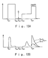
- Fig. 13 shows one example of the conventionally executed contained oxygen analyzing method.
- the method of removing the oxide film shown in Fig. 13 corresponds to a method described in Japanese Unexamined Patent Publication No. 6-148170.
- Fig. 13A shows a temperature change within a carbon furnace (a graphite crucible) in correspondence to a procedure of the contained oxygen analysis
- Fig. 13B shows a change in amount of signals detected by the infrared gas analyzer.
- the carbon furnace is preliminarily heated at a high temperature, for example, 3000°C or the like, between time points T P11 and T P12 .
- the surface oxide film is reduced by inputting the sample to be measured into the graphite crucible in which the preliminary heating is finished, at a time point T P13 , and heating the sample to be measured to a temperature equal to or less than a melting point (for example, in a range between 900°C and 1400°C), between time points T P14 and T P15.5
- a melting point for example, in a range between 900°C and 1400°C
- Fig. 14 shows another example of the contained oxygen analyzing method, in which Fig. 14A shows a temperature change within the carbon furnace in correspondence to a procedure of the contained oxygen analysis, and Fig. 14B shows a change in mount of signals detected by the infrared gas analyzer.
- the graphite crucible is preliminarily heated between time points T P21 and T P22 , and thereafter, the sample to be measured is input into the graphite crucible at a time point T P23 .
- the surface oxygen is removed by heating the sample to be measured, for example, to 1050°C in the graphite inert gas between time point Tp 2 » and T P25 .
- the sample to be measured is cooled in the inert gas to be approximately room temperature, and at a time point T P26 the sample to be measured is taken out to the ambient air so as to be oxidized.
- the sample to be measured is input into the graphite crucible at a time point T P29 , after a preliminary heating is again applied to the graphite crucible between time points T P27 and T P28 .
- the surface oxygen is again removed by heating the sample to be measured, for example, to 1050°C in the graphite inert gas between time points T P30 and T P31 , and an amount of oxidation of the oxide film is measured from a signal amount S P21 at this time.
- the sample to be measured is cooled to be approximately room temperature in the inert gas, at a time point T P32 and the sample to be measured is taken out to the ambient air so as to be again oxidized.
- a metal solvent is input into the graphite crucible at a time point T P35, and a metal bath of the metal flux is prepared in the graphite crucible by heating an inner side of the graphite crucible, for example, to 2400°C .
- a signal amount S P22 of a gas generated by inputting the sample to be measured into the graphite crucible is measured at a time point T P36 .
- a contained oxygen amount (a bulk oxygen) of the sample to be measured is determined by subtracting the oxygen amount of the oxide film calculated from the signal amount mentioned above from a whole oxygen amount to be calculated (S P22 - S P21).
- the subtraction (S P22 - S P21 ) is executed on the assumption that the amount of the surface oxidation oxygen at the first time is equal to the amount of the surface oxidation oxygen at the second time, however, it is unavoidable that both the amounts fluctuate due to a time being in contact with the ambient air or the other conditions.
- the present invention is made by taking the matters mentioned above into consideration, and an object of the present invention is to provide a contained oxygen analyzing apparatus and a contained oxygen analyzing method which can accurately measure a trace amount of contained oxygen contained in a metal (particularly, a steel) corresponding to a sample to be measured.
- a contained oxygen analyzing apparatus for analyzing an amount of contained oxygen in a sample to be measured, by inputting the sample to be measured and a metal flux into a graphite crucible within an analyzing furnace and heating and dissolving them, comprising:
- the contained oxygen analyzing apparatus mentioned above it is possible to prevent the oxide film from being reformed on the surface of the sample to be measured as well as it is possible to completely reduce the oxide film attached to the surface of the sample to be measured, and it is possible to accurately measure the contained oxygen (the bulk oxygen) in the inner portion of the sample to be measured, by dissolving the sample to be measured from which the oxide film is removed.
- the oxide film has been already removed at a time of dissolving the sample to be measured, it is not necessary to carry out a staged heating of the graphite crucible which has been conventionally carried out for removing the oxide film of the sample to be measured, and it is possible to carry out a measurement of the contained oxygen amount in a state in which the inner side of the analyzing furnace is always kept at a fixed temperature. That is, it is possible to completely remove the signals caused by the gas always generating from the graphite crucible at a corresponding amount to the temperature as a base line (a reference value), and it is possible to improve an accuracy at that degree.
- the preliminary reducing furnace is independently provided from the analyzing furnace, it is possible to carry out the preliminary heating of the sample to be measured in parallel to the motion of inputting the metal flux into the graphite crucible and heating and dissolving the metal flux, and it is possible to reduce a time required for measurement.
- the structure may be made such that the preliminary reducing furnace has a preliminary reducing crucible which is arranged in a horizontal direction in such a manner as to be communicated and connected to an upper portion of the graphite crucible, and a step portion which holds the sample to be measured within the crucible by inhibiting the sample to be measured within the crucible from moving in the horizontal direction, and the sample inputting means has an actuator which introduces the sample to be measured into the analyzing furnace by moving the sample to be measured in the horizontal direction against the step portion (claim 2).
- a contained oxygen analyzing apparatus for analyzing an amount of contained oxygen in a sample to be measured, by inputting the sample to be measured and a metal flux into a graphite crucible within an analyzing furnace and heating and dissolving them, comprising:
- the contained oxygen analyzing apparatus mentioned above it is possible to completely reduce the oxide film attached to the surface of the sample to be measured so as to accurately measure only the contained oxygen (the bulk oxygen) in the inner portion of the sample to be measured. Further, since the staged heating of the graphite crucible is not carried out, it is possible to measure the trace quantity of contained oxygen in a state of always keeping the inner side of the analyzing furnace at the fixed temperature, and it is possible to improve an accuracy by completely removing the gas generated from the graphite crucible as the base line.
- the preliminary reducing furnace is provided independently from the main body of the contained oxygen analyzing apparatus having the analyzing furnace, it is possible to carry out the preliminary heating of the sample to be measured in parallel to the motion of inputting the metal flux into the graphite crucible and heating and dissolving the metal flux, and it is possible to reduce a time required for measurement.
- the opening portion is formed in the conventional contained oxygen analyzing apparatus, it is possible to transfer the sample to be measured after the preliminary reducing is applied into the analyzing furnace in a state of being isolated from the ambient air, and it is possible to analyze the trace quantity of contained oxygen.
- the state being isolated from the ambient air is formed by the flow of the inert gas, it is possible to securely inhibit the intrusion of the ambient air by the flow (pressure) of the inert gas even when any gap which may form an intrusion path for the ambient air exists in the sample holding body, and it is possible to securely keep the state of being isolated from the ambient air. That is, the structure of the sample holding body has a size capable of receiving the preliminary reducing crucible and a construction capable of purging by the inert gas. Further, since the lid body is formed in the opening portion, it is possible to restrict the gas amount of the inert gas discharged from the opening portion, and it is possible to reduce a running cost at that degree.
- the structure may be made such that the apparatus has a lid body capable of opening and closing the discharge port for the inert gas in the another end side of the sample holding body from one end side thereof (claim 4). In this case, it is possible to restrict the gas amount of the inert gas discharged from the sample holding body, and it is possible to reduce the running cost at that degree.
- a contained oxygen analyzing apparatus for analyzing an amount of contained oxygen in a sample to be measured, by inputting the sample to be measured and a metal flux into a graphite crucible within an analyzing furnace and heating and dissolving them, comprising:
- the contained oxygen analyzing apparatus mentioned above it is possible to completely reduce the oxide film attached to the surface of the sample to be measured so as to accurately measure only the contained oxygen (the bulk oxygen) in the inner portion of the sample to be measured. Further, since the staged heating of the graphite crucible is not carried out, it is possible to measure the trace quantity of contained oxygen in a state of always keeping the inner side of the analyzing furnace at the fixed temperature, and it is possible to improve an accuracy by completely removing the gas generated from the graphite crucible as the base line.
- the structure may be made such that the sample to be measured is a steel, and the sample take-out means has a magnetic force induction portion capable of taking out the steel from the inner side of the graphite crucible due to a suction by a magnetic force (claim 6). In this case, it is possible to easily take out the steel from the graphite crucible, and the apparatus structure becomes simple.
- the structure may be made such that the sample to be measured is a steel, and the sample take-out means has a rod body forming a magnetic force application portion at least in a leading end portion thereof and capable of taking-out the steel within the graphite crucible from the inner side of the graphite crucible on the basis of an adsorption caused by a magnetic force (claim 7).
- the sample take-out means has a rod body forming a magnetic force application portion at least in a leading end portion thereof and capable of taking-out the steel within the graphite crucible from the inner side of the graphite crucible on the basis of an adsorption caused by a magnetic force (claim 7).
- the sample take-out means has a rod body forming a magnetic force application portion at least in a leading end portion thereof and capable of taking-out the steel within the graphite crucible from the inner side of the graphite crucible on the basis of an adsorption caused by a magnetic force (claim 7).
- the magnetic force application portion can be simplified in structure by being formed by a permanent magnet, and it is possible to reduce the manufacturing cost at that degree, however, it is possible to easily achieve an automatic control by setting the magnetic force application portion to an electromagnet.
- the structure may be made such that the sample take-out means has a gripping means for gripping the sample to be measured by a leading end portion so as to take out the sample to be measured from the inner side of the graphite crucible, a fiber scope for checking a state near the leading end portion by an image, a display portion displaying the image transmitted by the fiber scope, and an operation portion for the gripping means (claim 8).
- a gripping means for gripping the sample to be measured by a leading end portion so as to take out the sample to be measured from the inner side of the graphite crucible
- a fiber scope for checking a state near the leading end portion by an image
- a display portion displaying the image transmitted by the fiber scope
- an operation portion for the gripping means claim 8
- a contained oxygen analyzing method comprising the steps of:
- a contained oxygen analyzing method comprising the steps of:
- a contained oxygen analyzing method comprising the steps of:
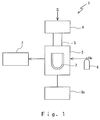
- FIGs. 1 to 3 show a structure of a contained oxygen analyzing apparatus 1 in accordance with a first invention.
- a sample S to be measured in the present embodiment is, for example, a steel, and a contained oxygen analyzing apparatus 1 in accordance with the present invention is structured such as to measure a trace quantity of contained oxygen contained in an inner portion of the steel.
- Fig. 4 is a view showing a modified embodiment of the embodiment in Fig. 2.
- the contained oxygen analyzing apparatus 1 in accordance with the present embodiment has an analyzing furnace 3 which includes a graphite crucible 2 (hereinafter, refer also to as a carbon furnace 2) for inserting the sample S to be measured into an inner portion thereof, a preliminary reducing furnace 4 which preliminarily reduces an oxide film on a surface of the sample S to be measured by heating the sample S to be measured at a temperature equal to or less than a melting point thereof, a communication passage 5 for communicating and connecting the preliminary reducing furnace 4 to the analyzing furnace 3, a gas bomb 6 which supplies an inert gas such as helium (He) or the like to the analyzing furnace 3, and an infrared gas analyzer 7 which measures an amount of generated gas by analyzing the inert gas passing through the analyzing furnace 3.
- reference symbol 3p denotes a power control portion for the analyzing furnace 3.
- Fig. 2 shows a more particular structure of the contained oxygen analyzing apparatus 1.
- the graphite crucible 2 is a closed-end tubular body having an approximately U-shaped cross section, and is placed within a space A shut off from the ambient air so as to be clamped between an upper electrode 3a and a lower electrode 3b which constitute the analyzing furnace 3.
- Reference symbol 3c denotes a power source which heats the graphite crucible 2 by applying an electric current controlled by the power control portion 3p to a portion between both of the electrodes 3a and 3b
- reference symbol 3d denotes an introduction portion which introduces the sample S to be measured and a metal flux F in an upper portion of the analyzing furnace 3 and introduces the helium gas (He)
- reference symbol 3e denotes a discharge portion for the helium gas (He) passing through the graphite crucible 2.
- Reference symbol 3f denotes an inner space of the upper electrode 3a. It is possible to rapidly cool the graphite crucible 2, for example, by circulating a cooling water within the inner space 3f. Further, a flow passage switching valve 7a is formed between the analyzing furnace 3 and the analyzer 7, whereby it is possible to select whether the gas fed from the discharge portion 3e is supplied to the analyzer 7 or the gas is discharged.
- the preliminary reducing furnace 4 has an approximately tubular preliminary reducing crucible 4b which is arranged in a horizontal direction, for example, in such a manner as to wind a heater 4a, a power source 4c for the heater 4a, and a step portion 4d for holding the sample S to be measured within the graphite crucible 4b by inhibiting the sample S to be measured from moving in a horizontal direction within the graphite crucible 4b. Further, one end side of the analyzing furnace 3 is communicated and connected to the communication passage 5, and a discharge hole 4e for the helium gas (He) is formed in another end side.
- He helium gas
- a heat source of the preliminary reducing furnace 4 is not limited to an electric furnace using the heater 4a, and it is possible to use various types of heat sources such as an impulse furnace, an induction heating furnace or the like.
- the gas used for the reduction is not limited to the helium (He), and the other inert gases such as an argon (Ar) or the like may be used.
- the other gases than the inert gas may be used, for example, a material such as a hydrogen or the like which tends to be combined with an oxygen may be used.
- the sample S to be measured is structured such that an oxide film on a surface layer thereof can be reduced by . being heated in a state of being isolated from the ambient air.
- Reference numeral 8 denotes a sample inputting means for inputting the sample S to be measured which is positioned within the preliminary reducing furnace 4, into the graphite crucible 2.
- the sample inputting means 8 has an electromagnet 8a which adsorbs the sample S to be measured on the basis of a suction force using a magnetic force, a power source 8b thereof, a rod body 8c made of a magnetic body for applying a smaller magnetic force to the sample S to be measured, and a slide driving portion 8d which moves the sample S to be measured in the horizontal direction against the step portion 4d by moving the rod body 8c in the horizontal direction, in the present embodiment. That is, each of the portions 8a to 8d moves the sample S to be measured in the horizontal direction against the step portion 4d, thereby structuring an actuator introducing the sample S to be measured into the analyzing furnace 3.
- the present invention does not limit this structure. That is, the permanent magnet may be used for the sample inputting means 8, and the magnetic force may be directly applied to the sample S to be measured without using the rod body 8c.
- the sample S to be measured is not the magnetic body, it is possible to move the sample S to be measured in the horizontal direction against the step portion 4d by pressing out from another end side of the preliminary reducing furnace 4 by the rod body 8e, as shown by a modified embodiment in Fig. 4. That is, the sample S to be measured in accordance with the present invention is not limited to the magnetic body such as the steel or the like, and may be a nonferrous metal such as a copper or the like, and in this case, various modifications can be considered for the sample inputting means 8.
- the communication passage 5 has a columnar sample holder 5a for temporarily receiving the sample S to be measured input by the sample inputting means 8 and thereafter inputting into the graphite crucible 2, and a columnar sample holder 5b for temporarily receiving the metal flux F, for example, tin (Sn) in the same manner and inputting into the graphite crucible 2.
- F metal flux
- NDIR non-dispersive infrared gas analyzer
- the kinds thereof is not limited as far as it can accurately analyze the oxygen corresponding to the sample to be measured. That is, a mass spectrometer may be used in place of the NDIR.
- the structure may be made such as to simultaneously analyze the contained amount of the other components than the oxygen contained in the sample S to be measured, by using a multi component analyzer such as a Fourier transform infrared gas analyzer (FTIR) or the like.
- FTIR Fourier transform infrared gas analyzer
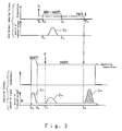
- Fig. 3 is a view describing a method of analyzing the oxygen contained in the sample S to be measured with using the contained oxygen analyzing apparatus 1.
- An upper half in Fig. 3 shows a motion within the preliminary reducing furnace 4, and a lower half shows a motion within the analyzing furnace 3. In both cases, there are shown a change of a temperature within the furnace in accordance with a time and a change of an amount of reduced oxygen thereby in accordance with a time in a corresponding manner.
- the sample S to be measured is input into the preliminary furnace 4 at a time point T 11 , and the inner side of the preliminary furnace 4 is heated at a temperature equal to or less than a boiling point (1540°C ) of the steel, for example, a temperature between 900 and 1400°C, and a degasification for removing the oxide film on the surface thereof is applied, at a time point T 12 .
- the oxygen is reduced from the oxide film on the surface of the sample S to be measured, thereby being converted into a gas such as a carbon monoxide (CO) or the like, as shown by S 1 and being discharged from the discharge hole 4e.
- CO carbon monoxide
- This preliminary reduction is carried out, for example, for five minutes, and the sample S to be measured is cooled by stopping the heating applied by the heater 4a at a time point T 13
- the preliminary reduction mentioned above is carried out while supplying the helium gas (He)
- the periphery of the sample S to be measured becomes in a state of being securely isolated from the ambient air on the basis of the circulation of the helium gas (He).
- the stream of the helium gas (He) is generated from the inner side of the communication passage 5 or the preliminary reducing furnace 4 toward the outer side via the gap, and an inside pressure becomes higher than an outside pressure, so that the ambient air does not move against this stream so as to flow into the inner side.
- a magnetism is generated by the electromagnet 8a at a time point T 14 at which the sample S to be measured (the steel) is lowered to be equal to or less than the Curie temperature, and the rod body 8c is slid by the slide driving portion 8d. Accordingly, it is possible to adsorb the steel S by using the suction force generated by the magnetic force so as to move the steel S just above the communication passage 5 over the step portion 4d, and it is possible to input the steel S into the sample holder 5a by stopping the current application to the electromagnet 8a.
- the inner side of the analyzing furnace 3 is heated, for example, up close to 3000°C and the oxygen therein is degasified, at a time point T 15 , and a temperature within the analyzing furnace 3 is controlled to an analyzing temperature (for example, 2400°C ) at a time point T 16.
- the carbon monoxide (CO) generated within the analyzing furnace 3 is temporarily increased and again reduced as shown by a curve S 12 .
- the gas (CO) is generated in a steady manner from the graphite crucible 2 after being degasified, even in the state of being controlled to the analyzing temperature.
- reference symbol S 13 denotes an amount of the carbon monoxide (CO) generated by inputting the tin Sn. It is possible to securely dissolve the heat oxide by using the metal flux F as shown in the present embodiment, and it is possible to prevent the generated carbon monoxide (CO) from being collected.
- the oxygen in the flux F is finally all discharged, and the concentration of the carbon monoxide (CO) detected by the analyzer 7 is stable. Then, the metal flux F' of the dissolved tin Sn (refer to Fig. 2) is formed within the graphite crucible 2.
- the degasification of the graphite crucible 2 within the analyzing furnace 3 and the formation of the metal flux F' by the tin Sn may be simultaneously carried out in parallel to the reduction of the oxide film of the sample S to be measured within the preliminary reducing furnace 4, whereby it is possible to shorten the measuring time.
- the concentration of the carbon monoxide (CO) detected at this time is stored as a reference value (a base line) B for measurement, and the sample S to be measured after being preliminarily reduced is input into the graphite crucible 2 by using the sample holder 5a at a time point T 18 , in a state in which the temperature of the graphite crucible 2 is make stable at the analyzing temperature.
- Reference symbol S 14 denotes an amount of the carbon monoxide (CO) generated in accordance with the input of the sample S to be measured.
- the weight of the oxide film is extremely small, for example, about 150 nm. That is, it is 0.000015/3.15 with respect to the sample having a radius 3.15 mm, and can be disregarded with respect to the whole weight.
- the present invention since a differential time is provided between the input of the metal flux F and the input of the sample S to be measured, it is possible to heat at the fixed analyzing temperature until the oxygen contained in the metal flux F' and the carbon monoxide (CO) generated in the steady manner from the graphite crucible 2 are stable, and input the sample S to be measured after setting them at the stable time point to the base line B, so that it is possible to securely correct the base line B. Accordingly, it is possible to dramatically improve the accuracy of analysis.
- the surface oxide film is removed only one time, the measurement can be rapidly carried out in comparison with the prior art shown in Fig. 14.
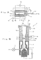
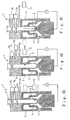
- Figs. 5 to 7 is a view showing a second embodiment in accordance with the present invention, in which Fig. 5A shows a structure of a preliminary reducing furnace 10 corresponding to the preliminary reducing furnace 4 mentioned above, Fig. 5B shows a structure of a main body 1' of the contained oxygen analyzing apparatus 1, and Figs. 7A to 7C are views describing a method of inputting the sample S to be measured into the oxygen analyzing apparatus main body 1' .
- Figs. 5 to 7 since parts having the same reference symbols as those in Figs. 1 to 4 are the same or the corresponding parts, a detailed description thereof will be omitted.
- the preliminary reducing furnace 10 in accordance with the present embodiment is provided independently from the oxygen analyzing apparatus main body 1', and is structured such as to heat the sample S to be measured by inserting a sample holding body 11 into an inner portion thereof, thereby reducing the oxide film formed on a surface thereof.
- the preliminary reducing furnace 10 has, for example, a guide tube 10a capable of inserting the sample holding body 11 to an inner portion thereof, a heater 10b wound around an outer periphery of the guide tube 10a, and a power source 10c supplying an electric power to the heater 10b.
- the sample holding body 11 has, for example, a preliminary reducing crucible 11a heating the sample S to be measured in a state of positioning the sample S to be measured in an inner portion thereof, a tube body 11b brought into contact with an outer periphery of the preliminary reducing crucible 11a, thereby holding the preliminary reducing crucible 11a in an inner portion thereof, a closed-end tube body 11c rotatably mounted so as to cover the tube body 11b, a lid body 11e forming a door for closing one end side of the tube body 11b and an inflow port 11d for the helium gas (He) corresponding to the inert gas, and a flow rate regulating valve 11f for the helium gas (He).
- a preliminary reducing crucible 11a heating the sample S to be measured in a state of positioning the sample S to be measured in an inner portion thereof
- a tube body 11b brought into contact with an outer periphery of the preliminary reducing crucible 11a, thereby holding the preliminary reducing cruci
- a discharge port 11g for the helium gas (He) is formed at a position deflecting from a center thereof, in another end side of the tube body 11c, and a flange 11h for rotating the tube body 11c is formed in one end side.
- a step portion 11h protruding to an inner portion at a position closing the discharge port 11g and used for holding the sample S to be measured in the inner portion is formed in another end side of the preliminary reducing crucible 11a, and a discharge port 11j for discharging some of the helium gas (He) is formed in the step portion 11h.
- the bottom surface of the tube body 11c is structured such as to form a lid body 11k opening and closing another end side of the sample holding body 11 in correspondence to the rotation of the tube body 11c.
- the analyzing apparatus main body 1' forms a hopper 12 to which the sample S to be measured within the sample holding body 11 can be input while keeping the state of being isolated from the ambient air.
- the structure of the hopper 12 has an opening portion 12a which is communicated, for example, with the analyzing furnace 3 and can keep the state of being isolated from the ambient air by circulating the helium gas (He) corresponding to one example of the inert gas to an inner portion thereof, a lid body 12b which opens and closes an open end portion of the opening portion 12a, a hook 12c for holding a closed state of the lid body 12b, and a seal 12d . (an 0-ring) for keeping the opening portion 12a in an air-proof state from an external portion in a state of closing the lid body 12b.
- He helium gas
- Fig. 6 shows a modified embodiment of the hopper 12 shown in Fig. 5B.
- Reference symbol 12e denotes a lid body which slides in a horizontal direction with respect to the opening portion 12a. It is possible to make a volumetric capacity of the opening portion 12a small by making the structure as the present embodiment. That is, the structure of the lid body may be such as to close the opening portion 12a by rotating so as to press the opening portion 12a from the above, or open and close by sliding laterally. However, it is possible to reduce the volumetric capacity of the opening portion 12a so as to make the amount of consumption of the inert gas (He) consumed in correspondence to the opening and closing motion of the lid body 12e further small, by sliding the lid body 12e in a lateral direction.
- He inert gas
- the hopper 12 forming the lid body 12b which opens and closes mainly in correspondence to the rotation in the vertical direction, however, it is possible to input the sample S to be measured in accordance with approximately the same way in the hopper 12 forming the lid body 12e which opens and closes on the basis of the sliding motion.
- the lid body 12b is opened so as to make it possible to insert the sample holding body 11.
- the helium gas (He) goes on flowing out from both of the opening portion 12a and the discharge port 11g, and the sample S to be measured keeps the state of being isolated from the ambient air within the sample holding body 11.
- the sample S to be measured is moved to a position deflecting from the step portion 11i by slightly tilting the sample holding body 11. In this case, in order to make it easy to insert the sample holding body 11, it is desirable to form an outer diameter somewhat smaller than an inner diameter of the opening portion 12a.
- the sample holding body 11 is inserted into the opening portion 12a. Since the helium gas (He) supplied to both of the sample holding body 11 and the hopper 12 is discharged to the external portion through a gap formed between an inner periphery of the opening portion 12a and an outer periphery of the sample holding body 11 at this time, a flow rate thereof is increased, so that no ambient air flows into against this flow. That is, a space A' within the opening portion 12a securely becomes in the state of being isolated from the ambient air.
- He helium gas
- a position of the discharge port 11g is aligned with a position of . the sample S to be measured by carrying out the rotating operation of the flange 11h from one end side of the sample holding body 11 as shown in Fig. 7C, whereby it is possible to open the lid body 11k and it is possible to move the sample S to be measured to the sample holder 5a in a state of being isolated from the ambient air. That is, it is possible to keep the state of being completely isolated from the ambient air due to the flow of the inert gas (He), also at a time of moving the sample S to be measured by using the sample holding body 11.
- He inert gas
- the structure of the present embodiment it is possible to obtain the same effect as that of first embodiment shown in Figs. 1 to 4, and it is possible to make the structure in the side of the main body 1' of the contained oxygen analyzing apparatus 1 simple, by risking to form the preliminary reducing furnace 10 as the independent body. Further, the structure can be achieved only by mounting the hopper 12 to the existing contained oxygen analyzing apparatus 1. In this case, the measuring procedure is the same as the first embodiment.
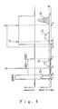
- Figs. 8 and 9 are views showing a third embodiment in accordance with the present invention, in which Figs. 8A to 8C are views showing a structure and a motion of the contained oxygen analyzing apparatus 1 in accordance with the present embodiment, and Fig. 9 is a view showing a relation between a temperature within the analyzing furnace 3 and an amount of generated gas (an amount of signal in the analyzer 7).
- Figs. 8 and 9 since parts having the same reference symbols as those in Figs. 1 to 7 are the same parts or the corresponding parts, a detailed description thereof will be omitted.
- a position of the sample holder 5a which holds the sample S to be measured so as to input into the graphite crucible 2 and a position of the sample holder 5b which holds the metal flux F so as to input into the graphite crucible 2 in the present embodiment are arranged so as to be inverse to those shown in Figs. 2 and 4.
- a magnet 13 is arranged on a side surface of the graphite crucible 2, and the magnet 13 can be moved to at least three positions respectively shown in Figs. 8A to 8C in accordance with a control from a control portion (not shown) of the contained oxygen analyzing apparatus 1.
- the sample S to be measured by the contained oxygen analyzing apparatus 1 in accordance with the present invention is a magnetic body (desirably, a ferromagnetic body) such as the steel or the like, and the metal flux F is a non-magnetic body (a material which is not a ferromagnetic body). That is, the magnet 13 corresponds to one example of a sample take-out means for temporarily taking out the sample S to be measured within the graphite crucible 2 in the state of being isolated from the ambient air and holding the sample S to be measured.
- the graphite crucible 2 is heated to about 3000°C , is degasified and thereafter the analyzing furnace 3 is left until the inside temperature decreased equal to or less than a boiling point of the steel 1540°C . Further, at a time point T 33, the oxide film on the surface of the steel S is reduced by inputting the steel S into the graphite crucible 2 and controlling the temperature within the analyzing furnace 3 between 900°C and 1400°C .
- the heating of the analyzing furnace 3 is stopped at a time point T 34 , the steel S is left until the temperature thereof is cooled down to be equal to or less than the Curie temperature (780°C). Then, at a time point T 35 , the steel S is sucked on the basis of the magnetic force by arranging the magnet 13 at a position shown in Fig. 8A, and the steel S is moved from the outer portion of the analyzing furnace 3 to a portion which is not affected by a heat of the carbon furnace 2, by moving the magnet 13 upward, as shown in Fig. 8B. That is, the magnet 13 in accordance with the present embodiment structures a magnetic force induction portion which can take out the steel S from the inner side of the graphite crucible 2 by using the suction force caused by the magnetic force.
- the temperature within the analyzing furnace 3 is heated to an analyzing temperature (2400°C ) at a time point T 36 , and at a time point T 37 , the communication passage 5 is opened by sliding the sample holder 5a as shown in Fig. 8B, and the powder or granular metal flux F is input into the graphite crucible 2 by rotating the sample holder 5b. Accordingly, the flux F forms a metal flux F', the oxygen therein is discharged, and this is stored as the base line B in a state that the amount of gas generated from the graphite crucible 2 is stable.
- the steel S is released from the influence of the magnetic force by moving the magnet 13 away from the analyzing furnace 3 as shown in Fig. 8C, thereby being inserted into the graphite crucible 2. Accordingly, it is possible to accurately measure the contained oxygen in the inner portion of the steel S on the basis of a signal S 14 .
- the contained oxygen analyzing apparatus 1 can carry out an accurate analysis using the metal flux F while the structure thereof is extremely simple, and it is possible to reduce a manufacturing cost thereof.
- the sample S to be measured after the oxide film is reduced can be analyzed without being taken out from the contained oxygen analyzing apparatus 1, it is possible to securely keep the state of being isolated from the ambient air, and it is possible to securely prevent the reformation of the oxide film. Further, since it is not necessary to repeat a process of removing the oxide film of the sample S to be measured as in the conventional embodiment shown in Fig. 14 again and again, it is possible to rapidly analyze.
- the sample take-out means may be formed as a scooping up structure using a suction, a rod body or the like.
- Figs. 10 and 11 are views showing a fourth embodiment in accordance with the present invention.
- the fourth embodiment corresponds to an embodiment obtained by modifying the contained oxygen analyzing apparatus in accordance with the third embodiment shown in Figs. 8 and 9.
- Figs. 10A to 10E are view showing a structure and a motion of the contained oxygen analyzing apparatus 1 in accordance with the present embodiment
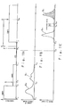
- Figs. 11A to 11C are views showing a relation between the temperature within the analyzing furnace 3 and the amount of the generated gas (the amount of signals of the analyzer 7).
- Fig. 11A shows a temperature change of the graphite crucible 2
- Figs. 11B and 11C show an amount of oxygen reduced by heating.
- the sample S to be measured in the present embodiment is the magnetic body, for example, the steel.
- the metal flux F is the non-magnetic body, for example, the tin.
- reference numeral 14 denotes a rod body corresponding to one example of the sample take-out means for temporarily taking out and holding the sample S to be measured in the state of being isolated from the ambient air
- reference numeral 15 denotes a magnetic force application portion formed by a permanent magnet (a ferromagnetic body) mounted to a leading end portion 14a of the rod body 14
- reference numeral 16 denotes a lid body formed so as to be capable of closing the communication passage 5
- reference numeral 17 denotes an actuator sliding the rod body 14 in a vertical direction.
- the rod body 14 mentioned above extends through the lid body 16 so as to freely move forward and backward (vertically move) with respect to the lid body 16 and be airtight with respect to the ambient air.
- the flow passage switching valve 7a (refer to Fig. 2) is formed between the analyzing furnace 3 and the analyzer 7. That is, the preliminary reduction of the sample to be measured and the degasification of the graphite crucible 2 can be controlled by switching the flow passage switching valve so that the oxide gas does not flow through the analyzer 7.
- the graphite crucible 2 is heated to about 2900°C in a state shown in Fig. 10A, first at time points T 41 to T 42 .
- a degasification for the graphite crucible 2 is applied.
- the gas flow passage for the carbon monoxide (CO) or the like generated due to the reduction is switched by the flow passage switching valve 7a or the like so as to prevent the gas from flowing into the analyzer 7.
- the temperature is regulated, for example, to about 1000°C .
- the graphite crucible 2 can be quickly cooled by circulating a cooling water within the internal space 3f of the upper electrode 3a shown in Fig. 2.
- the gas flow passage is switched so that the analyzing furnace 3 is communicated with the analyzer 7.
- the metal flux F is input into the graphite crucible 2 by sliding the sample holder 5b, and the rod body 14 is dropped into the graphite crucible 2 by using the actuator 17 mentioned above.
- the temperature of the steel S is cooled down to be equal to or less than the Curie temperature (780°C), and both of the metal flux F and the steel S are received within the graphite crucible 2, however, only the magnetic body, the steel S is adsorbed by the magnetic force of the permanent magnet 15 mounted to the leading end portion 14a of the rod body 14.
- the actuator 17 lifts up the rod body 14, it is possible to adsorb only the steel S to the leading end portion 14a thereof so as to take out only the steel S from the inner side of the graphite crucible 2.
- the magnetic force of the permanent magnet 15 is set to a magnitude sufficient to selectively adsorb and lift up the steel S within the graphite crucible 2, it is not necessary to charge a strong magnetism without discretion and it is possible to have almost no influence to the periphery.
- the structure is made simple by using the permanent magnet corresponding to the ferromagnetic body as the magnetic force application portion 15, however, the magnetic force application portion 15 formed in the leading end portion 14a of the rod body 14 is not limited to the permanent magnet, but may be formed by an electromagnet mounted to a base end portion of the rod body 14 corresponding to the magnetic body.
- a magnitude of an adsorbing force applied to the steel S can be regulated by a magnitude of an electric power supplied to the electromagnet.
- the graphite crucible 2 When lifting up the steel S from the inner side of the graphite crucible 2, at the next time point T 47, the graphite crucible 2 is again heated and the temperature thereof is regulated so as to be between 2200°C and 2400°C . At this time, the metal flux F is dissolved, and the oxygen contained therein is reduced, whereby the oxide gas shown by a curve S 13 is detected by the detector 7. Further, when the metal flux F is dissolved so as to form the metal flux F', and the oxygen contained therein is reduced, the concentration of the oxide gas becomes stable.
- the reference value B is next set between time points T 48 and T 49 . Further, at a time point T 50 , the steel S is again input into the graphite crucible 2 as shown in Fig. 10E. At this time, the actuator 17 further sucks the rod body 14 into a through hole 16a (refer to Fig. 10) for the rod body 14 formed in the lid body 16 by further lifting up the rod body 14, thereby making the force applied to the steel S from the permanent magnet 15 smaller than the force of gravity and inputting the steel S into the graphite crucible 2.
- the structure of the sample take-out means a structure similar to an endoscope for medical use.
- Fig. 12 is a view showing a fifth embodiment in accordance with the present invention.
- the contained oxygen analyzing apparatus 1 shown in Fig. 12 corresponds to a further modified embodiment of the sample take-out means 13 and 14 shown in Figs. 8 and 10, and since parts having the same reference symbols as those in Figs. 1 to 11 are the same of the corresponding members, a detailed description thereof will be omitted.
- reference numeral 18 denotes a gripping means having a clamp 18a for gripping the sample S to be measured in a leading end portion and having an operation portion 18b for carrying out a tilting motion of the clamp 18a in a two-dimensional direction X and Y and a gripping operation (in a direction of an arrow C) of the clamp 18a
- reference numeral 19 denotes a fiber scope which is arranged so as to be along the gripping means 18 and is used for checking a state near a leading end portion thereof by means of an image V
- reference numeral 20 denotes a display portion which displays the image V transmitted by a pixel fiber 19a of the fiber scope 19
- reference numeral 21 denotes a light source which irradiates a light to the inner side of the graphite crucible 2 by using a floodlight fiber 19b of the fiber scope 19. That is, a take-out means 22 in the present embodiment is constituted by the gripping means 18, the fiber scope 19, the display portion 20 and the light source 21.
- the contained oxygen analyzing apparatus 1 in accordance with the present invention analyzes approximately in the same manner as that of the fourth embodiment shown in Figs. 10 and 11. Then, at a time of taking out the sample S to be measured in the time point T 46 in Fig. 11, the gripping means is dropped down within the graphite crucible 2 as shown by an arrow D. At this time, an operator can real-time check the condition near the leading end portion of the gripping means 18 by using the image V displayed on the display portion 20, and can operate the operation portion 18b while seeing the image V.
- the contained oxygen analyzing apparatus 1 in accordance with the present invention is not limited to the gripping means 18, the fiber scope 19, the display portion 20 and the light source 21 in the detailed structure. Further, in the present embodiment, there is shown the embodiment which the operator manually operates, however, the structure may be made such that each of the operations shown by the arrows C to E, X and Y mentioned above is electrically controlled from a side of the main body of the contained oxygen analyzing apparatus 1 by making it possible to control electrically the operation portion 8b or the like.
- the present invention is not limited to using the metal flux F.
- the embodiment using the helium gas (He) as the example of the inert gas there is shown the embodiment using the helium gas (He) as the example of the inert gas, however, it goes without saying that an argon gas (Ar) of the other inert gases can be used in place of the helium gas (He).
- the contained oxygen analyzing apparatus and the contained oxygen analyzing method on the basis of the present invention it is possible to quantitatively analyze the trace quantity of contained oxygen existing within the sample to be measured with a high accuracy, without being affected by the oxide film generated on the surface of the sample to be measured, while being the simple structure.
Landscapes
- Health & Medical Sciences (AREA)
- Life Sciences & Earth Sciences (AREA)
- Chemical & Material Sciences (AREA)
- Biochemistry (AREA)
- Food Science & Technology (AREA)
- Medicinal Chemistry (AREA)
- Physics & Mathematics (AREA)
- Analytical Chemistry (AREA)
- Engineering & Computer Science (AREA)
- General Health & Medical Sciences (AREA)
- General Physics & Mathematics (AREA)
- Immunology (AREA)
- Pathology (AREA)
- Investigating Or Analyzing Non-Biological Materials By The Use Of Chemical Means (AREA)
- Investigating And Analyzing Materials By Characteristic Methods (AREA)
- Sampling And Sample Adjustment (AREA)
Abstract
The invention provides an apparatus and a method of determining trace
amounts of oxygen in a metal, in particular steel. The analysing
apparatus comprises a preliminary reducing furnace with a tubular
graphite crucible and an analysing furnace with a conventional graphite
crucible. The furnaces are connected via a communication passage
(isolated from the ambient air) that contains means for transferring the
sample from the preliminary reducing to the analysing furnace. The
preliminary reducing furnace is used for reducing oxides on the surface
of the sample prior to introducing it into the graphite crucible located
in the analysing furnace. The oxygen content is determined by analysing
the gas generated by the sample in the heated graphite crucible using
Infra-Red spectroscopy. A metal flux is used for determining a reference
value for the generated gas amount.
Description
The present invention relates to a contained oxygen analyzing apparatus,
and more particularly to a contained oxygen analyzing apparatus and a contained
oxygen analyzing method which can measure a trace amount of contained oxygen by
removing an oxide film on a sample surface in a measurement of a small amount of
oxygen for a sample to be measured, for example, a metal (particularly, a
steel).
For example, as a method of quantitatively analyzing an oxygen contained in
the steel, there is generally used a method obtained by combining a fusion
extraction method in an inert gas, an infrared absorbing method and a thermal
conductivity method. The fusion extraction method in the inert gas, the
infrared absorbing method and the thermal conductivity method comprise the
steps of arranging a graphite crucible in which a sample to be measured is
inserted, within a heating furnace, heating and fusing the steel corresponding
to the sample to be measured while supplying the inert gas, and analyzing a
carbon monoxide or a carbon dioxide generated at this time, for example, by an
infrared gas analyzer.
In this case, in order to accurately detect the oxygen contained at a trace
quantity in the sample to be measured such as the steel, it is necessary to
previously remove an oil content, a dirty or the like attached to a surface of
the sample to be measured (hereinafter, refer to as an attachment), and the
oxide film. Further, in order to remove the attachment attached to the surface
of the sample to be measured, a preliminary treatment is applied to the sample
by means of heating the sample at 400°C to 600°C for about ten minutes.
Fig. 13 shows one example of the conventionally executed contained oxygen
analyzing method. The method of removing the oxide film shown in Fig. 13
corresponds to a method described in Japanese Unexamined Patent Publication No.
6-148170. Fig. 13A shows a temperature change within a carbon furnace (a
graphite crucible) in correspondence to a procedure of the contained oxygen
analysis, and Fig. 13B shows a change in amount of signals detected by the
infrared gas analyzer.
In Fig. 13, first, the carbon furnace is preliminarily heated at a high
temperature, for example, 3000°C or the like, between time points TP11 and
TP12. Next, the surface oxide film is reduced by inputting the sample to be
measured into the graphite crucible in which the preliminary heating is
finished, at a time point TP13, and heating the sample to be measured to a
temperature equal to or less than a melting point (for example, in a range
between 900°C and 1400°C), between time points TP14 and TP15.5 Then, an amount
of the contained oxygen in the sample to be measured is analyzed by increasing
a temperature of the carbon furnace to be equal to or more than 1400°C (in
particular, 2400°C ).
Fig. 14 shows another example of the contained oxygen analyzing method, in
which Fig. 14A shows a temperature change within the carbon furnace in
correspondence to a procedure of the contained oxygen analysis, and Fig. 14B
shows a change in mount of signals detected by the infrared gas analyzer.
In accordance with the method shown in Fig. 14, first, the graphite
crucible is preliminarily heated between time points TP21 and TP22, and
thereafter, the sample to be measured is input into the graphite crucible at a
time point TP23. Next, the surface oxygen is removed by heating the sample to
be measured, for example, to 1050°C in the graphite inert gas between time
point Tp2» and TP25. Then, the sample to be measured is cooled in the inert gas
to be approximately room temperature, and at a time point TP26 the sample to be
measured is taken out to the ambient air so as to be oxidized.
Next, the sample to be measured is input into the graphite crucible at a
time point TP29, after a preliminary heating is again applied to the graphite
crucible between time points TP27 and TP28. Next, the surface oxygen is again
removed by heating the sample to be measured, for example, to 1050°C in the
graphite inert gas between time points TP30 and TP31, and an amount of oxidation
of the oxide film is measured from a signal amount SP21 at this time. Then,
the sample to be measured is cooled to be approximately room temperature in the
inert gas, at a time point TP32 and the sample to be measured is taken out to
the ambient air so as to be again oxidized.
Further, after the preliminary heating is applied for the third time
between time points TP33 and TP34, a metal solvent is input into the graphite
crucible at a time point TP35, and a metal bath of the metal flux is prepared in
the graphite crucible by heating an inner side of the graphite crucible, for
example, to 2400°C . Then, a signal amount SP22 of a gas generated by inputting
the sample to be measured into the graphite crucible is measured at a time point
TP36 . Accordingly, a contained oxygen amount (a bulk oxygen) of the sample to
be measured is determined by subtracting the oxygen amount of the oxide film
calculated from the signal amount mentioned above from a whole oxygen amount to
be calculated (SP22 - SP21).
However, in accordance with the conventional oxygen analyzing method shown
in Fig. 13, since the signal SP11 caused by the carbon monoxide gas generated
from the graphite crucible is increased at a time of increasing a temperature of
the graphite crucible from a preliminary heating temperature between 900 and
1400°C to 1400°C or more (in particular, 2400°C), an influence of fluctuation
in the signal SP11 is added to the measured signal amount SP13, so that there
is a problem that a magnitude of the signal SP12 caused by the oxygen contained
in the sample to be measured can not be accurately determined.
Especially, since the increase of the signal SP11 caused by the carbon
monoxide gas generated from the graphite crucible applies a great influence in
accordance that the oxygen contained in the sample to be measured is at an
extremely trace quantity, it is impossible to restrict a result of analysis to
be equal to or less than 0.5 ppm at the maximum, for example, with respect to
an indicated value of 2.9 ppm. That is, in accordance with the conventional
oxygen analyzing method shown in Fig. 13, it is impossible to analyze an
extremely trace quantity of contained oxygen.
Further, in accordance with the conventional oxygen analyzing method shown
in Fig. 14, it is necessary to measure the surface oxidation oxygen for two
times, so that it is unavoidable to take a lot of time for measurement. In
addition, the subtraction (SP22 - SP21) is executed on the assumption that the
amount of the surface oxidation oxygen at the first time is equal to the amount
of the surface oxidation oxygen at the second time, however, it is unavoidable
that both the amounts fluctuate due to a time being in contact with the ambient
air or the other conditions. That is, in accordance with this example, it is
impossible to restrict a dispersion of the surface oxidation to be equal to or
less than 0.5 ppm at the maximum with respect to the value of analysis in the
case of measuring the extremely trace quantity of contained oxygen about 2.9µ
g/g.
The present invention is made by taking the matters mentioned above into
consideration, and an object of the present invention is to provide a contained
oxygen analyzing apparatus and a contained oxygen analyzing method which can
accurately measure a trace amount of contained oxygen contained in a metal
(particularly, a steel) corresponding to a sample to be measured.
In order to achieve the object mentioned above, in accordance with a first
aspect of the present invention, there is provided a contained oxygen analyzing
apparatus for analyzing an amount of contained oxygen in a sample to be
measured, by inputting the sample to be measured and a metal flux into a
graphite crucible within an analyzing furnace and heating and dissolving them,
comprising:
Accordingly, by using the contained oxygen analyzing apparatus mentioned
above, it is possible to prevent the oxide film from being reformed on the
surface of the sample to be measured as well as it is possible to completely
reduce the oxide film attached to the surface of the sample to be measured, and
it is possible to accurately measure the contained oxygen (the bulk oxygen) in
the inner portion of the sample to be measured, by dissolving the sample to be
measured from which the oxide film is removed.
Further, since the oxide film has been already removed at a time of
dissolving the sample to be measured, it is not necessary to carry out a staged
heating of the graphite crucible which has been conventionally carried out for
removing the oxide film of the sample to be measured, and it is possible to
carry out a measurement of the contained oxygen amount in a state in which the
inner side of the analyzing furnace is always kept at a fixed temperature.
That is, it is possible to completely remove the signals caused by the gas
always generating from the graphite crucible at a corresponding amount to the
temperature as a base line (a reference value), and it is possible to improve an
accuracy at that degree.
Further, since the preliminary reducing furnace is independently provided
from the analyzing furnace, it is possible to carry out the preliminary heating
of the sample to be measured in parallel to the motion of inputting the metal
flux into the graphite crucible and heating and dissolving the metal flux, and
it is possible to reduce a time required for measurement.
The structure may be made such that the preliminary reducing furnace has a
preliminary reducing crucible which is arranged in a horizontal direction in
such a manner as to be communicated and connected to an upper portion of the
graphite crucible, and a step portion which holds the sample to be measured
within the crucible by inhibiting the sample to be measured within the crucible
from moving in the horizontal direction, and the sample inputting means has an
actuator which introduces the sample to be measured into the analyzing furnace
by moving the sample to be measured in the horizontal direction against the step
portion (claim 2). In this case, it is possible to transfer the sample to be
measured from which the surface oxide film is removed into the analyzing
furnace from the inner side of the preliminary reducing furnace on the basis of
the simple structure, and it is possible to easily and securely inhibit the
oxide film from being reformed with respect to the sample to be measured, by
filling the inner side of the communication passage with the inert gas and
evacuating.
In accordance with a second aspect of the present invention, there is
provided a contained oxygen analyzing apparatus for analyzing an amount of
contained oxygen in a sample to be measured, by inputting the sample to be
measured and a metal flux into a graphite crucible within an analyzing furnace
and heating and dissolving them, comprising:
Accordingly, by using the contained oxygen analyzing apparatus mentioned
above, it is possible to completely reduce the oxide film attached to the
surface of the sample to be measured so as to accurately measure only the
contained oxygen (the bulk oxygen) in the inner portion of the sample to be
measured. Further, since the staged heating of the graphite crucible is not
carried out, it is possible to measure the trace quantity of contained oxygen
in a state of always keeping the inner side of the analyzing furnace at the
fixed temperature, and it is possible to improve an accuracy by completely
removing the gas generated from the graphite crucible as the base line.
Further, since the preliminary reducing furnace is provided independently
from the main body of the contained oxygen analyzing apparatus having the
analyzing furnace, it is possible to carry out the preliminary heating of the
sample to be measured in parallel to the motion of inputting the metal flux
into the graphite crucible and heating and dissolving the metal flux, and it is
possible to reduce a time required for measurement. Further, since the opening
portion is formed in the conventional contained oxygen analyzing apparatus, it
is possible to transfer the sample to be measured after the preliminary reducing
is applied into the analyzing furnace in a state of being isolated from the
ambient air, and it is possible to analyze the trace quantity of contained
oxygen.
Further, since the state being isolated from the ambient air is formed by
the flow of the inert gas, it is possible to securely inhibit the intrusion of
the ambient air by the flow (pressure) of the inert gas even when any gap which
may form an intrusion path for the ambient air exists in the sample holding
body, and it is possible to securely keep the state of being isolated from the
ambient air. That is, the structure of the sample holding body has a size
capable of receiving the preliminary reducing crucible and a construction
capable of purging by the inert gas. Further, since the lid body is formed in
the opening portion, it is possible to restrict the gas amount of the inert gas
discharged from the opening portion, and it is possible to reduce a running
cost at that degree.
The structure may be made such that the apparatus has a lid body capable of
opening and closing the discharge port for the inert gas in the another end
side of the sample holding body from one end side thereof (claim 4). In this
case, it is possible to restrict the gas amount of the inert gas discharged
from the sample holding body, and it is possible to reduce the running cost at
that degree.
In accordance with a third aspect of the present invention, there is
provided a contained oxygen analyzing apparatus for analyzing an amount of
contained oxygen in a sample to be measured, by inputting the sample to be
measured and a metal flux into a graphite crucible within an analyzing furnace
and heating and dissolving them, comprising:
Accordingly, by using the contained oxygen analyzing apparatus mentioned
above, it is possible to completely reduce the oxide film attached to the
surface of the sample to be measured so as to accurately measure only the
contained oxygen (the bulk oxygen) in the inner portion of the sample to be
measured. Further, since the staged heating of the graphite crucible is not
carried out, it is possible to measure the trace quantity of contained oxygen
in a state of always keeping the inner side of the analyzing furnace at the
fixed temperature, and it is possible to improve an accuracy by completely
removing the gas generated from the graphite crucible as the base line.
Further, it is possible to achieve a simplification and a downsizing of the
apparatus structure by carrying out the preliminary heating of the sample to be
measured within the analyzing furnace. Further, since a volumetric capacity of
a portion forming the state of being isolated from the ambient air is reduced,
it is possible to form the state of being isolated from the ambient air by a low
cost.
The structure may be made such that the sample to be measured is a steel,
and the sample take-out means has a magnetic force induction portion capable of
taking out the steel from the inner side of the graphite crucible due to a
suction by a magnetic force (claim 6). In this case, it is possible to easily
take out the steel from the graphite crucible, and the apparatus structure
becomes simple.
The structure may be made such that the sample to be measured is a steel,
and the sample take-out means has a rod body forming a magnetic force
application portion at least in a leading end portion thereof and capable of
taking-out the steel within the graphite crucible from the inner side of the
graphite crucible on the basis of an adsorption caused by a magnetic force
(claim 7). In this case, it is possible to securely adsorb the steel without
blindly strengthening the magnetic force generated from the magnetic force
application portion formed in the leading end portion of the rod body, so that
an energy saving is achieved and motions of peripheral equipment are not
affected at all. Further, since the motion of taking out the steel from the
inner side of the graphite crucible on the basis of the adsorption of the
magnetic force is sufficiently achieved by a vertical slide of the rod body, it
is possible to easily achieve an automation.
In this case, the magnetic force application portion can be simplified in
structure by being formed by a permanent magnet, and it is possible to reduce
the manufacturing cost at that degree, however, it is possible to easily
achieve an automatic control by setting the magnetic force application portion
to an electromagnet.
The structure may be made such that the sample take-out means has a
gripping means for gripping the sample to be measured by a leading end portion
so as to take out the sample to be measured from the inner side of the graphite
crucible, a fiber scope for checking a state near the leading end portion by an
image, a display portion displaying the image transmitted by the fiber scope,
and an operation portion for the gripping means (claim 8). In this case, it is
possible to analyze the contained oxygen amount without selecting a material of
the sample to be measured. Further, since it is possible to operate the
operation portion for the gripping means while viewing the image displayed on
the display portion, it is possible to securely grip the sample to be measured
in the state of being isolated from the ambient air so as to take out this from
the inner side of the graphite crucible, and it is possible to again input into
the graphite crucible.
In accordance with a fourth aspect of the present invention, there is
provided a contained oxygen analyzing method comprising the steps of:
In accordance with a fifth aspect of the present invention, there is
provided a contained oxygen analyzing method comprising the steps of:
In accordance with a sixth aspect of the present invention, there is
provided a contained oxygen analyzing method comprising the steps of:
That is, since it is possible to input the sample to be measured from which
the surface oxide film is removed into the graphite crucible, after previously
removing the surface oxide film of the sample to be measured, keeping the sample
to be measured in the state of being isolated from the ambient air, and
determining the gas amount as the reference value in the state in which the gas
amount generated from the graphite crucible dissolving the metal flux becomes
stable, it is possible to accurately determine the generation amount of the gas
caused by the trace quantity of contained oxygen contained in the inner portion
of the sample to be measured by subtracting the reference value from all the
measured values.
A description will be given of embodiments in accordance with the present
invention with reference to the accompanying drawings. Figs. 1 to 3 show a
structure of a contained oxygen analyzing apparatus 1 in accordance with a
first invention. A sample S to be measured in the present embodiment is, for
example, a steel, and a contained oxygen analyzing apparatus 1 in accordance
with the present invention is structured such as to measure a trace quantity of
contained oxygen contained in an inner portion of the steel. Further, Fig. 4
is a view showing a modified embodiment of the embodiment in Fig. 2.
As shown in Fig. 1, the contained oxygen analyzing apparatus 1 in
accordance with the present embodiment has an analyzing furnace 3 which
includes a graphite crucible 2 (hereinafter, refer also to as a carbon furnace
2) for inserting the sample S to be measured into an inner portion thereof, a
preliminary reducing furnace 4 which preliminarily reduces an oxide film on a
surface of the sample S to be measured by heating the sample S to be measured at
a temperature equal to or less than a melting point thereof, a communication
passage 5 for communicating and connecting the preliminary reducing furnace 4 to
the analyzing furnace 3, a gas bomb 6 which supplies an inert gas such as
helium (He) or the like to the analyzing furnace 3, and an infrared gas
analyzer 7 which measures an amount of generated gas by analyzing the inert gas
passing through the analyzing furnace 3. Further, reference symbol 3p denotes
a power control portion for the analyzing furnace 3.
Fig. 2 shows a more particular structure of the contained oxygen analyzing
apparatus 1. In Fig. 2, the graphite crucible 2 is a closed-end tubular body
having an approximately U-shaped cross section, and is placed within a space A
shut off from the ambient air so as to be clamped between an upper electrode 3a
and a lower electrode 3b which constitute the analyzing furnace 3. Reference
symbol 3c denotes a power source which heats the graphite crucible 2 by
applying an electric current controlled by the power control portion 3p to a
portion between both of the electrodes 3a and 3b, reference symbol 3d denotes an
introduction portion which introduces the sample S to be measured and a metal
flux F in an upper portion of the analyzing furnace 3 and introduces the helium
gas (He), and reference symbol 3e denotes a discharge portion for the helium
gas (He) passing through the graphite crucible 2.
Reference symbol 3f denotes an inner space of the upper electrode 3a. It
is possible to rapidly cool the graphite crucible 2, for example, by
circulating a cooling water within the inner space 3f. Further, a flow passage
switching valve 7a is formed between the analyzing furnace 3 and the analyzer 7,
whereby it is possible to select whether the gas fed from the discharge portion
3e is supplied to the analyzer 7 or the gas is discharged.
The preliminary reducing furnace 4 has an approximately tubular preliminary
reducing crucible 4b which is arranged in a horizontal direction, for example,
in such a manner as to wind a heater 4a, a power source 4c for the heater 4a,
and a step portion 4d for holding the sample S to be measured within the
graphite crucible 4b by inhibiting the sample S to be measured from moving in a
horizontal direction within the graphite crucible 4b. Further, one end side of
the analyzing furnace 3 is communicated and connected to the communication
passage 5, and a discharge hole 4e for the helium gas (He) is formed in another
end side.
In this case, a heat source of the preliminary reducing furnace 4 is not
limited to an electric furnace using the heater 4a, and it is possible to use
various types of heat sources such as an impulse furnace, an induction heating
furnace or the like. Further, the gas used for the reduction is not limited to
the helium (He), and the other inert gases such as an argon (Ar) or the like
may be used. In addition, the other gases than the inert gas may be used, for
example, a material such as a hydrogen or the like which tends to be combined
with an oxygen may be used. In any case, the sample S to be measured is
structured such that an oxide film on a surface layer thereof can be reduced by
. being heated in a state of being isolated from the ambient air.
Reference numeral 8 denotes a sample inputting means for inputting the
sample S to be measured which is positioned within the preliminary reducing
furnace 4, into the graphite crucible 2. The sample inputting means 8 has an
electromagnet 8a which adsorbs the sample S to be measured on the basis of a
suction force using a magnetic force, a power source 8b thereof, a rod body 8c
made of a magnetic body for applying a smaller magnetic force to the sample S to
be measured, and a slide driving portion 8d which moves the sample S to be
measured in the horizontal direction against the step portion 4d by moving the
rod body 8c in the horizontal direction, in the present embodiment. That is,
each of the portions 8a to 8d moves the sample S to be measured in the
horizontal direction against the step portion 4d, thereby structuring an
actuator introducing the sample S to be measured into the analyzing furnace 3.
In this case, in accordance with the present embodiment, it is possible to
electrically control the transfer of the sample S to be measured with using the
sample inputting means 8, by using the electromagnet for the sample inputting
means 8, and it is possible to effectively apply a weak magnetic force to the
sample S to be measured by using the rod body 8c of the magnetic body, however,
the present invention does not limit this structure. That is, the permanent
magnet may be used for the sample inputting means 8, and the magnetic force may
be directly applied to the sample S to be measured without using the rod body
8c.
Further, in the case that the sample S to be measured is not the magnetic
body, it is possible to move the sample S to be measured in the horizontal
direction against the step portion 4d by pressing out from another end side of
the preliminary reducing furnace 4 by the rod body 8e, as shown by a modified
embodiment in Fig. 4. That is, the sample S to be measured in accordance with
the present invention is not limited to the magnetic body such as the steel or
the like, and may be a nonferrous metal such as a copper or the like, and in
this case, various modifications can be considered for the sample inputting
means 8.
The communication passage 5 has a columnar sample holder 5a for temporarily
receiving the sample S to be measured input by the sample inputting means 8 and
thereafter inputting into the graphite crucible 2, and a columnar sample holder
5b for temporarily receiving the metal flux F, for example, tin (Sn) in the
same manner and inputting into the graphite crucible 2. In this case, since
detailed structures of the sample holders 5a and 5b are as shown in Japanese
Unexamined Patent Publication No. 2000-55794 proposed by the inventors of the
present application, the detailed description will be omitted.
With regard to the analyzer 7, as an example of a concentration analyzer
capable of accurately analyzing a concentration of the oxygen, for example,
there can be listed up a non-dispersive infrared gas analyzer(NDIR), however,
the kinds thereof is not limited as far as it can accurately analyze the oxygen
corresponding to the sample to be measured. That is, a mass spectrometer may be
used in place of the NDIR. Further, the structure may be made such as to
simultaneously analyze the contained amount of the other components than the
oxygen contained in the sample S to be measured, by using a multi component
analyzer such as a Fourier transform infrared gas analyzer (FTIR) or the like.
Fig. 3 is a view describing a method of analyzing the oxygen contained in
the sample S to be measured with using the contained oxygen analyzing apparatus
1. An upper half in Fig. 3 shows a motion within the preliminary reducing
furnace 4, and a lower half shows a motion within the analyzing furnace 3. In
both cases, there are shown a change of a temperature within the furnace in
accordance with a time and a change of an amount of reduced oxygen thereby in
accordance with a time in a corresponding manner.
In this embodiment, the sample S to be measured is input into the
preliminary furnace 4 at a time point T11, and the inner side of the
preliminary furnace 4 is heated at a temperature equal to or less than a boiling
point (1540°C ) of the steel, for example, a temperature between 900 and 1400°C,
and a degasification for removing the oxide film on the surface thereof is
applied, at a time point T12. At this time, the oxygen is reduced from the
oxide film on the surface of the sample S to be measured, thereby being
converted into a gas such as a carbon monoxide (CO) or the like, as shown by S1
and being discharged from the discharge hole 4e.
This preliminary reduction is carried out, for example, for five minutes,
and the sample S to be measured is cooled by stopping the heating applied by
the heater 4a at a time point T13 In this case, since the preliminary
reduction mentioned above is carried out while supplying the helium gas (He),
the periphery of the sample S to be measured becomes in a state of being
securely isolated from the ambient air on the basis of the circulation of the
helium gas (He). In particular, even if the inner side of the communication
passage 5 and the preliminary reducing furnace 4 are not completely sealed but
have small gaps, the stream of the helium gas (He) is generated from the inner
side of the communication passage 5 or the preliminary reducing furnace 4 toward
the outer side via the gap, and an inside pressure becomes higher than an
outside pressure, so that the ambient air does not move against this stream so
as to flow into the inner side.
Further, a magnetism is generated by the electromagnet 8a at a time point T
14 at which the sample S to be measured (the steel) is lowered to be equal to or
less than the Curie temperature, and the rod body 8c is slid by the slide
driving portion 8d. Accordingly, it is possible to adsorb the steel S by using
the suction force generated by the magnetic force so as to move the steel S
just above the communication passage 5 over the step portion 4d, and it is
possible to input the steel S into the sample holder 5a by stopping the current
application to the electromagnet 8a.
On the other hand, within the analyzing furnace 3, the inner side of the
analyzing furnace 3 is heated, for example, up close to 3000°C and the oxygen
therein is degasified, at a time point T15, and a temperature within the
analyzing furnace 3 is controlled to an analyzing temperature (for example,
2400°C ) at a time point T16. The carbon monoxide (CO) generated within the
analyzing furnace 3 is temporarily increased and again reduced as shown by a
curve S12. In this case, the gas (CO) is generated in a steady manner from the
graphite crucible 2 after being degasified, even in the state of being
controlled to the analyzing temperature.
Next, when inputting the tin Sn corresponding to the powder or granular
metal flux F into the graphite crucible 2 by using the sample holder 5b at a
time point T17, the tin Sn is dissolved in correspondence thereto, and the
oxygen in the flux F is discharged, whereby the carbon monoxide (CO) is
generated.
In this case, reference symbol S13 denotes an amount of the carbon monoxide
(CO) generated by inputting the tin Sn. It is possible to securely dissolve
the heat oxide by using the metal flux F as shown in the present embodiment, and
it is possible to prevent the generated carbon monoxide (CO) from being
collected.
Further, when the inner side of the analyzing furnace 3 is made stable at
the analyzing temperature, the oxygen in the flux F is finally all discharged,
and the concentration of the carbon monoxide (CO) detected by the analyzer 7 is
stable. Then, the metal flux F' of the dissolved tin Sn (refer to Fig. 2) is
formed within the graphite crucible 2.
In this case, the degasification of the graphite crucible 2 within the
analyzing furnace 3 and the formation of the metal flux F' by the tin Sn may be
simultaneously carried out in parallel to the reduction of the oxide film of the
sample S to be measured within the preliminary reducing furnace 4, whereby it
is possible to shorten the measuring time.
Next, in a stage in which the concentration of the carbon monoxide (CO) is
stable, the concentration of the carbon monoxide (CO) detected at this time is
stored as a reference value (a base line) B for measurement, and the sample S
to be measured after being preliminarily reduced is input into the graphite
crucible 2 by using the sample holder 5a at a time point T18, in a state in
which the temperature of the graphite crucible 2 is make stable at the
analyzing temperature. Reference symbol S14 denotes an amount of the carbon
monoxide (CO) generated in accordance with the input of the sample S to be
measured.
Further, it is possible to accurately determine the amount of the oxygen
contained in the sample S to be measured, by integrating the measured value in
an upper part (an increased part) from the base line B. Since the surface
oxidization of the sample to be measured is 0.3µ g/g and an analysis target
level is about 3µg/g, an influence of a dispersion in measurement is great if
the oxygen contained in the oxide film is added to the result of analysis, so
that the formula R = 0.5 is established, however, since the present invention
can measure by completely removing the surface oxide film, it is possible to
improve an accuracy of analysis.
In this case, on the assumption that the whole weight of the sample S to be
measured is 1 g, the weight of the oxide film is extremely small, for example,
about 150 nm. That is, it is 0.000015/3.15 with respect to the sample having a
radius 3.15 mm, and can be disregarded with respect to the whole weight. In
other words, in a state in which the concentration of the oxide film is rich,
the oxide is
0.3 µg/(5.1 x π x 4/3 x 0.0004465 x 1000 µg) ≒ 0.3/9.54 ≒ 0.03,
and
O2 /Fe2 O3 = 32/(55.8 x 2 + 16 x 3) = 0.2.
Accordingly, since an average concentration of Fe2O3 contained in the thin
film of 150 nm is 0.2 x 15 % = 0.03, the accuracy of analysis is R = 0.1 with
respect to a value of analysis 3µ g/g, and is improved.
That is, in accordance with the present invention, since a differential
time is provided between the input of the metal flux F and the input of the
sample S to be measured, it is possible to heat at the fixed analyzing
temperature until the oxygen contained in the metal flux F' and the carbon
monoxide (CO) generated in the steady manner from the graphite crucible 2 are
stable, and input the sample S to be measured after setting them at the stable
time point to the base line B, so that it is possible to securely correct the
base line B. Accordingly, it is possible to dramatically improve the accuracy
of analysis. In addition, in accordance with the present invention, since the
surface oxide film is removed only one time, the measurement can be rapidly
carried out in comparison with the prior art shown in Fig. 14.
Figs. 5 to 7 is a view showing a second embodiment in accordance with the
present invention, in which Fig. 5A shows a structure of a preliminary reducing
furnace 10 corresponding to the preliminary reducing furnace 4 mentioned above,
Fig. 5B shows a structure of a main body 1' of the contained oxygen analyzing
apparatus 1, and Figs. 7A to 7C are views describing a method of inputting the
sample S to be measured into the oxygen analyzing apparatus main body 1' . In
the embodiment shown in Figs. 5 to 7, since parts having the same reference
symbols as those in Figs. 1 to 4 are the same or the corresponding parts, a
detailed description thereof will be omitted.
As shown in Fig. 5A, the preliminary reducing furnace 10 in accordance with
the present embodiment is provided independently from the oxygen analyzing
apparatus main body 1', and is structured such as to heat the sample S to be
measured by inserting a sample holding body 11 into an inner portion thereof,
thereby reducing the oxide film formed on a surface thereof.
The preliminary reducing furnace 10 has, for example, a guide tube 10a
capable of inserting the sample holding body 11 to an inner portion thereof, a
heater 10b wound around an outer periphery of the guide tube 10a, and a power
source 10c supplying an electric power to the heater 10b.
On the other hand, the sample holding body 11 has, for example, a
preliminary reducing crucible 11a heating the sample S to be measured in a
state of positioning the sample S to be measured in an inner portion thereof, a
tube body 11b brought into contact with an outer periphery of the preliminary
reducing crucible 11a, thereby holding the preliminary reducing crucible 11a in
an inner portion thereof, a closed-end tube body 11c rotatably mounted so as to
cover the tube body 11b, a lid body 11e forming a door for closing one end side
of the tube body 11b and an inflow port 11d for the helium gas (He)
corresponding to the inert gas, and a flow rate regulating valve 11f for the
helium gas (He).
Further, a discharge port 11g for the helium gas (He) is formed at a
position deflecting from a center thereof, in another end side of the tube body
11c, and a flange 11h for rotating the tube body 11c is formed in one end side.
On the other hand, a step portion 11h protruding to an inner portion at a
position closing the discharge port 11g and used for holding the sample S to be
measured in the inner portion is formed in another end side of the preliminary
reducing crucible 11a, and a discharge port 11j for discharging some of the
helium gas (He) is formed in the step portion 11h.
Further, the bottom surface of the tube body 11c is structured such as to
form a lid body 11k opening and closing another end side of the sample holding
body 11 in correspondence to the rotation of the tube body 11c.
Accordingly, when applying the electric current to the heater 10b while
circulating the helium gas (He) in a state of inserting another end side of the
sample holding body 11 into the guide tube 10a, it is possible to heat the
sample S to be measured while purging the inner side of the sample holding body
11 by the helium gas (He), and it is possible to reduce the oxide film of the
sample S to be measured while keeping the state of being isolated from the
ambient air.
On the other hand, as shown in Fig. 5B, the analyzing apparatus main body
1' forms a hopper 12 to which the sample S to be measured within the sample
holding body 11 can be input while keeping the state of being isolated from the
ambient air.
The structure of the hopper 12 has an opening portion 12a which is
communicated, for example, with the analyzing furnace 3 and can keep the state
of being isolated from the ambient air by circulating the helium gas (He)
corresponding to one example of the inert gas to an inner portion thereof, a
lid body 12b which opens and closes an open end portion of the opening portion
12a, a hook 12c for holding a closed state of the lid body 12b, and a seal 12d
. (an 0-ring) for keeping the opening portion 12a in an air-proof state from an
external portion in a state of closing the lid body 12b.
Accordingly, it is possible to input the metal flux F and input the sample
S to be measured via the same opening portion 12a, and it is possible to keep
the inner portion of the opening portion 12a in the state of being isolated from
the ambient air by purging the helium gas (He). Further, since it is possible
to restrict an amount of consumption of the helium gas (He) by closing the lid
body 12b, it is possible to restrict a running cost.
In this case, in accordance with the present embodiment, since the
structure is made such that both of the metal flux F and the sample S to be
measured can be input via the same opening portion 12a, it is desirable to slide
the sample holder 5a as illustrated at a time of making the sample holder 5b
hold the metal flux F, thereby opening the communication passage 5. In the same
manner, at a time of inputting the sample S to be measured held by the sample
holder 5a into the graphite crucible 2, it is desirable to slide the sample
holder 5b as shown in Fig. 7C so as to open the communication passage 5.
Further, it is possible to consider a modification that a sample holder is
formed by combining the sample holder 5a and the sample holder 5b to one unit.
Fig. 6 shows a modified embodiment of the hopper 12 shown in Fig. 5B.
Reference symbol 12e denotes a lid body which slides in a horizontal direction
with respect to the opening portion 12a. It is possible to make a volumetric
capacity of the opening portion 12a small by making the structure as the
present embodiment. That is, the structure of the lid body may be such as to
close the opening portion 12a by rotating so as to press the opening portion 12a
from the above, or open and close by sliding laterally. However, it is
possible to reduce the volumetric capacity of the opening portion 12a so as to
make the amount of consumption of the inert gas (He) consumed in correspondence
to the opening and closing motion of the lid body 12e further small, by sliding
the lid body 12e in a lateral direction.
Next, a description will be given of an operation at a time of inputting
. the sample S to be measured after being preliminarily reduced within the
preliminary reducing furnace 10 via the opening portion 12a, by using the
hopper 12. In this case, in the following Fig. 7, there is shown an example of
the hopper 12 forming the lid body 12b which opens and closes mainly in
correspondence to the rotation in the vertical direction, however, it is
possible to input the sample S to be measured in accordance with approximately
the same way in the hopper 12 forming the lid body 12e which opens and closes
on the basis of the sliding motion.
First, as shown in Fig. 7A, the lid body 12b is opened so as to make it
possible to insert the sample holding body 11. At this time, the helium gas
(He) goes on flowing out from both of the opening portion 12a and the discharge
port 11g, and the sample S to be measured keeps the state of being isolated from
the ambient air within the sample holding body 11. Further, the sample S to be
measured is moved to a position deflecting from the step portion 11i by
slightly tilting the sample holding body 11. In this case, in order to make it
easy to insert the sample holding body 11, it is desirable to form an outer
diameter somewhat smaller than an inner diameter of the opening portion 12a.
Next, as shown in Fig. 7B, the sample holding body 11 is inserted into the
opening portion 12a. Since the helium gas (He) supplied to both of the sample
holding body 11 and the hopper 12 is discharged to the external portion through
a gap formed between an inner periphery of the opening portion 12a and an outer
periphery of the sample holding body 11 at this time, a flow rate thereof is
increased, so that no ambient air flows into against this flow. That is, a
space A' within the opening portion 12a securely becomes in the state of being
isolated from the ambient air. In this case, when the outer diameter of the
sample holding body 11 is made too small in comparison with the inner diameter
of the opening portion 12a, the gap becomes wide, so that it is necessary to
discharge a sufficient flow rate of helium gas (He) so as to prevent the ambient
air from entering thereinto.
Further, a position of the discharge port 11g is aligned with a position of
. the sample S to be measured by carrying out the rotating operation of the
flange 11h from one end side of the sample holding body 11 as shown in Fig. 7C,
whereby it is possible to open the lid body 11k and it is possible to move the
sample S to be measured to the sample holder 5a in a state of being isolated
from the ambient air. That is, it is possible to keep the state of being
completely isolated from the ambient air due to the flow of the inert gas (He),
also at a time of moving the sample S to be measured by using the sample
holding body 11.
In accordance with the structure of the present embodiment, it is possible
to obtain the same effect as that of first embodiment shown in Figs. 1 to 4, and
it is possible to make the structure in the side of the main body 1' of the
contained oxygen analyzing apparatus 1 simple, by risking to form the
preliminary reducing furnace 10 as the independent body. Further, the
structure can be achieved only by mounting the hopper 12 to the existing
contained oxygen analyzing apparatus 1. In this case, the measuring procedure
is the same as the first embodiment.
Further, since the detailed structure mentioned above is exemplified so as
to easily describe the present invention, it goes without saying that the
detailed structure mentioned above does not limit the contents of the present
invention.
Figs. 8 and 9 are views showing a third embodiment in accordance with the
present invention, in which Figs. 8A to 8C are views showing a structure and a
motion of the contained oxygen analyzing apparatus 1 in accordance with the
present embodiment, and Fig. 9 is a view showing a relation between a
temperature within the analyzing furnace 3 and an amount of generated gas (an
amount of signal in the analyzer 7). In Figs. 8 and 9, since parts having the
same reference symbols as those in Figs. 1 to 7 are the same parts or the
corresponding parts, a detailed description thereof will be omitted.
In this case, a position of the sample holder 5a which holds the sample S
to be measured so as to input into the graphite crucible 2, and a position of
the sample holder 5b which holds the metal flux F so as to input into the
graphite crucible 2 in the present embodiment are arranged so as to be inverse
to those shown in Figs. 2 and 4.
In the contained oxygen analyzing apparatus 1 in accordance with the
present embodiment, a magnet 13 is arranged on a side surface of the graphite
crucible 2, and the magnet 13 can be moved to at least three positions
respectively shown in Figs. 8A to 8C in accordance with a control from a
control portion (not shown) of the contained oxygen analyzing apparatus 1.
Further, the sample S to be measured by the contained oxygen analyzing apparatus
1 in accordance with the present invention is a magnetic body (desirably, a
ferromagnetic body) such as the steel or the like, and the metal flux F is a
non-magnetic body (a material which is not a ferromagnetic body). That is, the
magnet 13 corresponds to one example of a sample take-out means for temporarily
taking out the sample S to be measured within the graphite crucible 2 in the
state of being isolated from the ambient air and holding the sample S to be
measured.
As shown in Fig. 9, in the contained oxygen analyzing apparatus 1 in
accordance with the present embodiment, first, between time points T31 and T32,
the graphite crucible 2 is heated to about 3000°C , is degasified and thereafter
the analyzing furnace 3 is left until the inside temperature decreased equal to
or less than a boiling point of the steel 1540°C . Further, at a time point
T33, the oxide film on the surface of the steel S is reduced by inputting the
steel S into the graphite crucible 2 and controlling the temperature within the
analyzing furnace 3 between 900°C and 1400°C .
Next, when the reduction of the oxygen film of the steel S is finished, the
heating of the analyzing furnace 3 is stopped at a time point T34, the steel S
is left until the temperature thereof is cooled down to be equal to or less than
the Curie temperature (780°C). Then, at a time point T35, the steel S is
sucked on the basis of the magnetic force by arranging the magnet 13 at a
position shown in Fig. 8A, and the steel S is moved from the outer portion of
the analyzing furnace 3 to a portion which is not affected by a heat of the
carbon furnace 2, by moving the magnet 13 upward, as shown in Fig. 8B. That is,
the magnet 13 in accordance with the present embodiment structures a magnetic
force induction portion which can take out the steel S from the inner side of
the graphite crucible 2 by using the suction force caused by the magnetic
force.
After moving the steel S, the temperature within the analyzing furnace 3 is
heated to an analyzing temperature (2400°C ) at a time point T36, and at a time
point T37, the communication passage 5 is opened by sliding the sample holder
5a as shown in Fig. 8B, and the powder or granular metal flux F is input into
the graphite crucible 2 by rotating the sample holder 5b. Accordingly, the
flux F forms a metal flux F', the oxygen therein is discharged, and this is
stored as the base line B in a state that the amount of gas generated from the
graphite crucible 2 is stable.
Further, at a time point T38, the steel S is released from the influence of
the magnetic force by moving the magnet 13 away from the analyzing furnace 3 as
shown in Fig. 8C, thereby being inserted into the graphite crucible 2.
Accordingly, it is possible to accurately measure the contained oxygen in the
inner portion of the steel S on the basis of a signal S14.
In accordance with the structure of the present embodiment, it is possible
to completely remove the oxide film formed on the surface of the sample S to be
measured within one graphite crucible 2, it is possible to accurately analyze
the amount of oxygen contained in the metal flux F by heating and dissolving the
metal flux F within the same graphite crucible 2 so as to degasify the metal
flux F, heating again the sample S to be measured in the state in which the base
line B is stable, and dissolving this. That is, the contained oxygen analyzing
apparatus 1 can carry out an accurate analysis using the metal flux F while the
structure thereof is extremely simple, and it is possible to reduce a
manufacturing cost thereof.
Further, since the sample S to be measured after the oxide film is reduced
can be analyzed without being taken out from the contained oxygen analyzing
apparatus 1, it is possible to securely keep the state of being isolated from
the ambient air, and it is possible to securely prevent the reformation of the
oxide film. Further, since it is not necessary to repeat a process of removing
the oxide film of the sample S to be measured as in the conventional embodiment
shown in Fig. 14 again and again, it is possible to rapidly analyze.
In this case, in the embodiment mentioned above, there is shown the
embodiment in which the permanent magnet is used as the magnet 13, however, an
electromagnet may be used in place thereof, and in this case, since it is
possible to electrically regulate a strength of the magnetic force applied to
the sample S to be measured, it is possible to reduce the movement of the
magnet. Further, as the embodiment shown in Fig. 2, it is possible to
effectively apply a weak magnetic force by using a rod body 8c.
In addition, in the case that the sample S to be measured is not the
magnetic body, the sample take-out means may be formed as a scooping up
structure using a suction, a rod body or the like.
Figs. 10 and 11 are views showing a fourth embodiment in accordance with
the present invention. The fourth embodiment corresponds to an embodiment
obtained by modifying the contained oxygen analyzing apparatus in accordance
with the third embodiment shown in Figs. 8 and 9. Further, Figs. 10A to 10E are
view showing a structure and a motion of the contained oxygen analyzing
apparatus 1 in accordance with the present embodiment, and Figs. 11A to 11C are
views showing a relation between the temperature within the analyzing furnace 3
and the amount of the generated gas (the amount of signals of the analyzer 7).
Fig. 11A shows a temperature change of the graphite crucible 2 and Figs. 11B
and 11C show an amount of oxygen reduced by heating.
In this case, also in Figs. 10 and 11, since parts having the same
reference symbols as those in Figs. 1 to 9 are the same or the corresponding
portions, a detailed description will be omitted. Further, the sample S to be
measured in the present embodiment is the magnetic body, for example, the steel.
On the other hand, the metal flux F is the non-magnetic body, for example, the
tin.
In Fig. 10, reference numeral 14 denotes a rod body corresponding to one
example of the sample take-out means for temporarily taking out and holding the
sample S to be measured in the state of being isolated from the ambient air,
reference numeral 15 denotes a magnetic force application portion formed by a
permanent magnet (a ferromagnetic body) mounted to a leading end portion 14a of
the rod body 14, reference numeral 16 denotes a lid body formed so as to be
capable of closing the communication passage 5, and reference numeral 17
denotes an actuator sliding the rod body 14 in a vertical direction. Further,
the rod body 14 mentioned above extends through the lid body 16 so as to freely
move forward and backward (vertically move) with respect to the lid body 16 and
be airtight with respect to the ambient air.
In this case, although an illustration is omitted also in the contained
oxygen analyzing apparatus 1 in accordance with the present embodiment, the
flow passage switching valve 7a (refer to Fig. 2) is formed between the
analyzing furnace 3 and the analyzer 7. That is, the preliminary reduction of
the sample to be measured and the degasification of the graphite crucible 2 can
be controlled by switching the flow passage switching valve so that the oxide
gas does not flow through the analyzer 7.
Next, a description will be given of an operation of the contained oxygen
analyzing apparatus 1 in accordance with the present embodiment. First, as
shown in Fig. 11A, the graphite crucible 2 is heated to about 2900°C in a
state shown in Fig. 10A, first at time points T41 to T42. At this time, as
shown by reference numeral S12 in Fig. 11B, a degasification for the graphite
crucible 2 is applied. However, the gas flow passage for the carbon monoxide
(CO) or the like generated due to the reduction is switched by the flow passage
switching valve 7a or the like so as to prevent the gas from flowing into the
analyzer 7. Thereafter, the temperature is regulated, for example, to about
1000°C .
Next, at a time point T43, as shown in Fig. 10B, when the steel S is input
into the graphite crucible 2 by sliding the sample holder 5a, the oxide film on
the surface of the steel S is reduced and the gas such as the carbon monoxide
(CO) or the like is discharged, as shown by reference numeral S11. Then, at a
time point T44 when a sufficient time has passed, the heating of the graphite
crucible 2 is stopped, and the temperature within the graphite crucible 2 is
cooled to about the room temperature 25°C .
In this case, the graphite crucible 2 can be quickly cooled by circulating
a cooling water within the internal space 3f of the upper electrode 3a shown in
Fig. 2. Next, at a time point T45, the gas flow passage is switched so that the
analyzing furnace 3 is communicated with the analyzer 7.
Further, at a time point T46, the metal flux F is input into the graphite
crucible 2 by sliding the sample holder 5b, and the rod body 14 is dropped into
the graphite crucible 2 by using the actuator 17 mentioned above. At this
time, the temperature of the steel S is cooled down to be equal to or less than
the Curie temperature (780°C), and both of the metal flux F and the steel S are
received within the graphite crucible 2, however, only the magnetic body, the
steel S is adsorbed by the magnetic force of the permanent magnet 15 mounted to
the leading end portion 14a of the rod body 14.
Accordingly, as shown in Fig. 10D, when the actuator 17 lifts up the rod
body 14, it is possible to adsorb only the steel S to the leading end portion
14a thereof so as to take out only the steel S from the inner side of the
graphite crucible 2. Further, the magnetic force of the permanent magnet 15 is
set to a magnitude sufficient to selectively adsorb and lift up the steel S
within the graphite crucible 2, it is not necessary to charge a strong magnetism
without discretion and it is possible to have almost no influence to the
periphery.
In addition, in accordance with the present embodiment, the structure is
made simple by using the permanent magnet corresponding to the ferromagnetic
body as the magnetic force application portion 15, however, the magnetic force
application portion 15 formed in the leading end portion 14a of the rod body 14
is not limited to the permanent magnet, but may be formed by an electromagnet
mounted to a base end portion of the rod body 14 corresponding to the magnetic
body. In this case, a magnitude of an adsorbing force applied to the steel S
can be regulated by a magnitude of an electric power supplied to the
electromagnet.
When lifting up the steel S from the inner side of the graphite crucible 2,
at the next time point T47, the graphite crucible 2 is again heated and the
temperature thereof is regulated so as to be between 2200°C and 2400°C . At
this time, the metal flux F is dissolved, and the oxygen contained therein is
reduced, whereby the oxide gas shown by a curve S13 is detected by the detector
7. Further, when the metal flux F is dissolved so as to form the metal flux F',
and the oxygen contained therein is reduced, the concentration of the oxide gas
becomes stable.
When the concentration of the oxide gas detected by the detector 7 becomes
stable, the reference value B is next set between time points T48 and T49.
Further, at a time point T50, the steel S is again input into the graphite
crucible 2 as shown in Fig. 10E. At this time, the actuator 17 further sucks
the rod body 14 into a through hole 16a (refer to Fig. 10) for the rod body 14
formed in the lid body 16 by further lifting up the rod body 14, thereby making
the force applied to the steel S from the permanent magnet 15 smaller than the
force of gravity and inputting the steel S into the graphite crucible 2.
However, in the case of forming the magnetic force application portion 15
by the electromagnet, it is possible to input the steel S into the graphite
crucible 2 by stopping the electric power supplied to the electromagnet.
In accordance with the structure mentioned above, since it is not necessary
to strengthen the magnetic force generated from the magnetic force application
portion 15 formed in the leading end portion 14a of the rod body 14 blindly, and
it is possible to adsorb the steel S securely, it is possible to simplify the
structure of the sample take-out means as much as possible. That is, it is
possible to reduce the manufacturing cost at that degree, an energy saving is
achieved, and there is no risk that the motion of the peripheral equipment is
affected. In addition, since it is sufficient to take out the steel from the
inner side of the graphite crucible in accordance with the adsorption by the
magnetic force only by vertically sliding the rod body, it is possible to easily
achieve the automation.
However, in the case that the sample S to be measured is not the magnetic
body, it is desirable to make the structure of the sample take-out means a
structure similar to an endoscope for medical use.
Fig. 12 is a view showing a fifth embodiment in accordance with the present
invention. The contained oxygen analyzing apparatus 1 shown in Fig. 12
corresponds to a further modified embodiment of the sample take-out means 13
and 14 shown in Figs. 8 and 10, and since parts having the same reference
symbols as those in Figs. 1 to 11 are the same of the corresponding members, a
detailed description thereof will be omitted.
In Fig. 12, reference numeral 18 denotes a gripping means having a clamp
18a for gripping the sample S to be measured in a leading end portion and having
an operation portion 18b for carrying out a tilting motion of the clamp 18a in
a two-dimensional direction X and Y and a gripping operation (in a direction of
an arrow C) of the clamp 18a, reference numeral 19 denotes a fiber scope which
is arranged so as to be along the gripping means 18 and is used for checking a
state near a leading end portion thereof by means of an image V, reference
numeral 20 denotes a display portion which displays the image V transmitted by
a pixel fiber 19a of the fiber scope 19, and reference numeral 21 denotes a
light source which irradiates a light to the inner side of the graphite crucible
2 by using a floodlight fiber 19b of the fiber scope 19. That is, a take-out
means 22 in the present embodiment is constituted by the gripping means 18, the
fiber scope 19, the display portion 20 and the light source 21.
The contained oxygen analyzing apparatus 1 in accordance with the present
invention analyzes approximately in the same manner as that of the fourth
embodiment shown in Figs. 10 and 11. Then, at a time of taking out the sample
S to be measured in the time point T46 in Fig. 11, the gripping means is dropped
down within the graphite crucible 2 as shown by an arrow D. At this time, an
operator can real-time check the condition near the leading end portion of the
gripping means 18 by using the image V displayed on the display portion 20, and
can operate the operation portion 18b while seeing the image V.
That is, since the operator can operate the operation portion 18b while
seeing the display portion 20 so as to pick up the sample S to be measured by
the clamp 18a, it is possible to securely pick up the sample S to be measured
whatever the sample S to be measure is made of, thereby taking out the sample
from the graphite crucible 2 as shown by an arrow E. Further, it is possible
to easily input the sample S to be measured in accordance with the operation of
the operation portion 18b at a time point T50.
In this case, the contained oxygen analyzing apparatus 1 in accordance with
the present invention is not limited to the gripping means 18, the fiber scope
19, the display portion 20 and the light source 21 in the detailed structure.
Further, in the present embodiment, there is shown the embodiment which the
operator manually operates, however, the structure may be made such that each
of the operations shown by the arrows C to E, X and Y mentioned above is
electrically controlled from a side of the main body of the contained oxygen
analyzing apparatus 1 by making it possible to control electrically the
operation portion 8b or the like.
In each of the embodiments mentioned above, there is shown the embodiment
in which the metal flux F is used for heating and dissolving the sample S to be
measured, whereby it is possible to securely dissolve the heat resisting oxide
even in the case that the oxygen concentration in the sample S to be measured is
high, however, the present invention is not limited to using the metal flux F.
Further, there is shown the embodiment using the helium gas (He) as the example
of the inert gas, however, it goes without saying that an argon gas (Ar) of the
other inert gases can be used in place of the helium gas (He).
In accordance with the contained oxygen analyzing apparatus and the
contained oxygen analyzing method on the basis of the present invention, it is
possible to quantitatively analyze the trace quantity of contained oxygen
existing within the sample to be measured with a high accuracy, without being
affected by the oxide film generated on the surface of the sample to be
measured, while being the simple structure.
Claims (11)
- A contained oxygen analyzing apparatus, which analyzes an amount of contained oxygen in a sample to be measured by inputting the sample to be measured and a metal flux into a graphite crucible within an analyzing furnace and heating and dissolving them, characterized by comprising:a preliminary reducing furnace which preliminarily reduces an oxide film on a surface of the sample to be measured by heating the sample to be measured to a temperature equal to or less than a melting point in a state of being apart from the ambient air; anda sample inputting means for inputting the sample to be measured into the graphite crucible via a communication passage apart from the ambient air.
- The contained oxygen analyzing apparatus as claimed 1, and further being constituted in such that the preliminary reducing furnace has a preliminary reducing crucible which is arranged in a horizontal direction in such a manner as to be communicated and connected to an upper portion of the graphite crucible, and a step portion which holds the sample to be measured within the crucible by inhibiting the sample to be measured within the crucible from moving in the horizontal direction, and the sample inputting means has an actuator which introduces the sample to be measured into the analyzing furnace by moving the sample to be measured in the horizontal direction against the step portion.
- A contained oxygen analyzing apparatus, which analyzes an amount of contained oxygen in a sample to be measured by inputting the sample to be measured and a metal flux into a graphite crucible within an analyzing furnace and heating and dissolving them, characterized by comprising:wherein the sample holding body has a preliminary reducing crucible having an inflow port for the inert gas in one end side and a discharge port for the inert gas in another end side, and a step portion holding the sample to be measured within the crucible in another end side of the crucible, and the sample to be measured after being preliminarily reduced is capable of being input into the graphite crucible in a state of being isolated from the ambient air by inserting the sample holding body into the opening portion after heating the sample to be measured to a temperature equal to or less than a melting point so as to preliminarily reduce an oxide film on a surface thereof in a state of inserting the sample holding body within the preliminary reducing furnace.a preliminary reducing furnace which is independently formed from a main body of the oxygen analyzing apparatus;a sample holding body which is structured such as to be inserted into the preliminary reducing furnace in a state of holding the sample to be measured;an opening portion which is communicated with the analyzing furnace, is capable of keeping a state of being isolated from the ambient air by circulating the inert gas to the inner portion, is capable of introducing the sample holding body and is provided in a side of the main body of the oxygen analyzing apparatus; anda lid body for the opening portion,
- The contained oxygen analyzing apparatus as claimed 3, and further being constituted in such that the apparatus has a lid body capable of opening and closing the discharge port for the inert gas in the another end side of the sample holding body from one end side thereof.
- A contained oxygen analyzing apparatus, which analyzes an amount of contained oxygen in a sample to be measured by inputting the sample to be measured and a metal flux into a graphite crucible within an analyzing furnace and heating and dissolving them, characterized by comprising:wherein the sample to be measured in which an oxide film on a surface thereof is preliminarily reduced by being heated to a temperature equal to or less than a melting point within the graphite crucible is taken out from the graphite crucible by using the sample take-out means, only the metal flux is input to the graphite crucible and heated and dissolved, and next the sample to be measured is input into the graphite crucible in a state of being isolated from the ambient air, thereby being heated and dissolved, so that the contained oxygen is allowed to be analyzed.a sample take-out means for temporarily taking out the sample to be measured within the graphite crucible in a state of being isolated from the ambient air and holding the sample to be measured,
- The contained oxygen analyzing apparatus as claimed 5, and further being constituted in such that the sample to be measured is a steel, and the sample take-out means has a magnetic force induction portion capable of taking out the steel from the inner side of the graphite crucible due to a suction by a magnetic force.
- The contained oxygen analyzing apparatus as claimed 5, and further being constituted in such that the sample to be measured is a steel, and the sample take-out means has a rod body forming a magnetic force application portion at least in a leading end portion thereof and capable of taking-out the steel within the graphite crucible from the inner side of the graphite crucible on the basis of an adsorption caused by a magnetic force.
- The contained oxygen analyzing apparatus as claimed 5, and further being constituted in such that the sample take-out means has a gripping means for gripping the sample to be measured by a leading end portion so as to take out the sample to be measured from the inner side of the graphite crucible, a fiber scope for checking a state near the leading end portion by an image, a display portion displaying the image transmitted by the fiber scope, and an operation portion for the gripping means.
- A contained oxygen analyzing method characterized by comprising the steps of:wherein the all steps are carried within a space communicated in a state of being isolated from the ambient air.heating a sample to be measured to a temperature equal to or less than a melting point so as to preliminarily reduce an oxide film on a surface thereof;inputting a metal flux into a graphite crucible and heating the metal flux to be equal to or more than a melting point thereof and equal to or less than a boiling point;reducing an oxygen contained in the metal flux by dissolving the metal flux;determining a gas amount as a reference value in a state in which the gas amount generated from the heated graphite crucible is stable;inputting the sample to be measured after the preliminary reduction into the graphite crucible, in a state of keeping a temperature of the graphite crucible at this time constant; andanalyzing the contained oxygen amount of the sample to be measured from an amount of generated gas increased thereby,
- A contained oxygen analyzing method characterized by comprising the steps of:wherein the all steps are carried out in a state of being isolated from the ambient air by a circulation of an inert gas.heating a sample to be measured to a temperature equal to or less than a melting point so as to preliminarily reduce an oxide film on a surface thereof;inputting a metal flux into a graphite crucible and heating the metal flux to be equal to or more than a melting point thereof and equal to or less than a boiling point;reducing an oxygen contained in the metal flux by dissolving the metal flux;determining a gas amount as a reference value in a state in which the gas amount generated from the heated graphite crucible is stable;inputting the sample to be measured after the preliminary reduction into the graphite crucible, in a state of keeping a temperature of the graphite crucible at this time constant; andanalyzing the contained oxygen amount of the sample to be measured from an amount of generated gas increased thereby,
- A contained oxygen analyzing method characterized by comprising the steps of:wherein the all steps are carried out a series of analyzing motions for in a state of being isolated from the ambient air.inputting a sample to be measured into a graphite crucible;heating the sample to be measured to a temperature equal to or less than a melting point so as to preliminarily reduce an oxide film on a surface thereof;taking out the sample to be measured from the graphite crucible;heating the graphite crucible into which a metal flux is input to be equal to or more than a melting point thereof and equal to or less than a boiling point;reducing and dissolving an oxygen contained in the metal flux by dissolving the metal flux;determining a gas amount as a reference value in a state in which the gas amount generated from the heated graphite crucible is stable;inputting the sample to be measured after the preliminary reduction into the graphite crucible, in a state of keeping a temperature of the graphite crucible at this time constant; andanalyzing the contained oxygen amount of the sample to be measured from an amount of generated gas increased thereby,
Applications Claiming Priority (4)
| Application Number | Priority Date | Filing Date | Title |
|---|---|---|---|
| JP2002155996 | 2002-05-29 | ||
| JP2002155996 | 2002-05-29 | ||
| JP2002373495 | 2002-12-25 | ||
| JP2002373495A JP4038123B2 (en) | 2002-05-29 | 2002-12-25 | Contained oxygen analyzer and contained oxygen analysis method |
Publications (1)
| Publication Number | Publication Date |
|---|---|
| EP1367391A1 true EP1367391A1 (en) | 2003-12-03 |
Family
ID=29422465
Family Applications (1)
| Application Number | Title | Priority Date | Filing Date |
|---|---|---|---|
| EP03012040A Withdrawn EP1367391A1 (en) | 2002-05-29 | 2003-05-28 | Method and apparatus for determining oxygen in a metal |
Country Status (4)
| Country | Link |
|---|---|
| US (1) | US7387764B2 (en) |
| EP (1) | EP1367391A1 (en) |
| JP (1) | JP4038123B2 (en) |
| CN (1) | CN100412532C (en) |
Cited By (2)
| Publication number | Priority date | Publication date | Assignee | Title |
|---|---|---|---|---|
| EP2426479A4 (en) * | 2009-04-30 | 2013-08-07 | Nippon Steel & Sumitomo Metal Corp | PROCESS FOR ANALYZING OXYGEN IN STEEL |
| CN112146730A (en) * | 2019-06-28 | 2020-12-29 | 北京铂阳顶荣光伏科技有限公司 | On-line measuring device and method for material quality in crucible |
Families Citing this family (21)
| Publication number | Priority date | Publication date | Assignee | Title |
|---|---|---|---|---|
| US7998417B2 (en) * | 2008-08-22 | 2011-08-16 | Board Of Regents, University Of Texas System | Particulate matter sensor with a heater |
| DE102009024055A1 (en) * | 2009-06-05 | 2010-12-09 | Netzsch-Gerätebau GmbH | Thermal analysis device and thermal analysis method |
| US8272279B2 (en) * | 2009-07-16 | 2012-09-25 | Seer Technology, Inc. | Systems and methods for chemical sampling in particulate laden gaseous environments |
| CN102393324B (en) * | 2011-08-01 | 2014-05-21 | 中国石油化工股份有限公司 | Sample pretreatment system of magnetic mechanical oxygen analyzer |
| CN103175777A (en) * | 2011-12-20 | 2013-06-26 | 贵州黎阳航空动力有限公司 | Analytical method for oxygen content in metal powder |
| CN103033529A (en) * | 2012-12-20 | 2013-04-10 | 贵州黎阳航空动力有限公司 | Hydrogen determining analyzer and method for analyzing content of hydrogen in metal powder |
| US9417126B2 (en) | 2014-06-27 | 2016-08-16 | International Business Machines Corporation | Spectrometer insert for measuring temperature-dependent optical properties |
| WO2018056419A1 (en) * | 2016-09-23 | 2018-03-29 | 株式会社堀場製作所 | Elemental analysis device and elemental analysis method |
| CN107525762B (en) * | 2017-10-17 | 2023-06-13 | 华能国际电力股份有限公司 | A test device and method for testing the adhesion of thermally grown oxide films on metal surfaces |
| CN107748089B (en) * | 2017-12-07 | 2020-09-15 | 华东理工大学 | A kind of sampling device, sampling method and application for determination of solubility of metal in molten salt |
| JP6989484B2 (en) * | 2018-12-20 | 2022-01-05 | 株式会社堀場製作所 | Sample pretreatment equipment and analysis system |
| CN112782208B (en) * | 2019-11-07 | 2022-06-14 | 上海梅山钢铁股份有限公司 | Test method for simulating surface oxidation of hot rolled steel plate |
| CN111257079B (en) * | 2020-02-28 | 2022-10-11 | 武汉科技大学 | A kind of preparation method of high oxygen iron powder standard sample |
| CN111505235B (en) * | 2020-04-30 | 2022-04-15 | 辽宁科技大学 | Method for determining the rate of interfacial oxygen transfer during smelting of superalloys |
| CN111721888B (en) * | 2020-06-05 | 2022-07-22 | 上海核工程研究设计院有限公司 | Equipment availability test device and test method under hydrogen combustion environment |
| CN112229745B (en) * | 2020-08-17 | 2022-07-15 | 中煤科工集团重庆研究院有限公司 | A kind of coal rock hardness detection test device and test method |
| WO2022091748A1 (en) * | 2020-11-02 | 2022-05-05 | 株式会社堀場製作所 | Element analysis method, element analysis device, and program for element analysis device |
| CN112834298B (en) * | 2020-12-30 | 2022-01-28 | 山西大学 | An anti-pollution sample processing system |
| CN114166651B (en) * | 2021-12-08 | 2024-10-29 | 北京科技大学 | Device and method for testing high-temperature water stress corrosion of micro-sample of in-service pressure equipment |
| CN116678845A (en) * | 2023-05-31 | 2023-09-01 | 西安奕斯伟材料科技股份有限公司 | Method and device for measuring oxygen content of silicon wafer |
| WO2025115509A1 (en) * | 2023-11-30 | 2025-06-05 | 株式会社堀場製作所 | Sample carrier and sample analysis system |
Citations (4)
| Publication number | Priority date | Publication date | Assignee | Title |
|---|---|---|---|---|
| JPH05281142A (en) * | 1992-03-30 | 1993-10-29 | Showa Denko Kk | Oxygen analyzing method for aluminum and aluminum alloy |
| JPH1073586A (en) * | 1996-08-30 | 1998-03-17 | Kawasaki Steel Corp | Method and apparatus for analyzing trace oxygen in metals |
| JP2000193657A (en) * | 1998-12-25 | 2000-07-14 | Horiba Ltd | Oxygen analysis method in sample and device |
| US6552786B1 (en) * | 1999-09-02 | 2003-04-22 | Berthold Gmbh & Co. Kg | Electrothermal furnace for an atomic absorption spectrometer |
Family Cites Families (1)
| Publication number | Priority date | Publication date | Assignee | Title |
|---|---|---|---|---|
| JPS6473586A (en) | 1987-09-14 | 1989-03-17 | Matsushita Electric Industrial Co Ltd | Optical disc reproducing device |
-
2002
- 2002-12-25 JP JP2002373495A patent/JP4038123B2/en not_active Expired - Fee Related
-
2003
- 2003-05-23 CN CNB031238696A patent/CN100412532C/en not_active Expired - Fee Related
- 2003-05-28 US US10/446,432 patent/US7387764B2/en not_active Expired - Fee Related
- 2003-05-28 EP EP03012040A patent/EP1367391A1/en not_active Withdrawn
Patent Citations (4)
| Publication number | Priority date | Publication date | Assignee | Title |
|---|---|---|---|---|
| JPH05281142A (en) * | 1992-03-30 | 1993-10-29 | Showa Denko Kk | Oxygen analyzing method for aluminum and aluminum alloy |
| JPH1073586A (en) * | 1996-08-30 | 1998-03-17 | Kawasaki Steel Corp | Method and apparatus for analyzing trace oxygen in metals |
| JP2000193657A (en) * | 1998-12-25 | 2000-07-14 | Horiba Ltd | Oxygen analysis method in sample and device |
| US6552786B1 (en) * | 1999-09-02 | 2003-04-22 | Berthold Gmbh & Co. Kg | Electrothermal furnace for an atomic absorption spectrometer |
Non-Patent Citations (3)
| Title |
|---|
| PATENT ABSTRACTS OF JAPAN vol. 018, no. 064 (P - 1685) 2 February 1994 (1994-02-02) * |
| PATENT ABSTRACTS OF JAPAN vol. 1998, no. 08 30 June 1998 (1998-06-30) * |
| PATENT ABSTRACTS OF JAPAN vol. 2000, no. 10 17 November 2000 (2000-11-17) * |
Cited By (2)
| Publication number | Priority date | Publication date | Assignee | Title |
|---|---|---|---|---|
| EP2426479A4 (en) * | 2009-04-30 | 2013-08-07 | Nippon Steel & Sumitomo Metal Corp | PROCESS FOR ANALYZING OXYGEN IN STEEL |
| CN112146730A (en) * | 2019-06-28 | 2020-12-29 | 北京铂阳顶荣光伏科技有限公司 | On-line measuring device and method for material quality in crucible |
Also Published As
| Publication number | Publication date |
|---|---|
| CN1474178A (en) | 2004-02-11 |
| US20040014234A1 (en) | 2004-01-22 |
| JP2004053577A (en) | 2004-02-19 |
| JP4038123B2 (en) | 2008-01-23 |
| US7387764B2 (en) | 2008-06-17 |
| CN100412532C (en) | 2008-08-20 |
Similar Documents
| Publication | Publication Date | Title |
|---|---|---|
| US7387764B2 (en) | Contained oxygen analyzing apparatus and contained analyzing method | |
| Verma et al. | Transient inclusion evolution during modification of alumina inclusions by calcium in liquid steel: Part I. Background, experimental techniques and analysis methods | |
| JP4560058B2 (en) | Contained oxygen analyzer and contained oxygen analysis method | |
| JP2014219398A (en) | Sample collection device and sample collection method | |
| JPWO2003071589A1 (en) | Heat treatment apparatus and heat treatment method | |
| US9993824B2 (en) | Microplate reader with lid lifter for microplates | |
| Distin et al. | Solubility of oxygen in liquid iron from 1785 to 1960 C. A new technique for the study of slag-metal equilibria | |
| US7922386B2 (en) | Thermal analysis apparatus | |
| CN102564806B (en) | For the method and apparatus analyzing the sample of molten metal | |
| US11662277B2 (en) | Method and apparatus for demolding and analyzing a direct analysis sample | |
| US7646534B2 (en) | Box-type motor-operated microscope | |
| CN104406893A (en) | Method for measuring dissolution speed of solid inclusion in slag | |
| US11105719B2 (en) | Sample preprocessing device and analysis system | |
| EP3388830A1 (en) | Analysis device | |
| CN111089947A (en) | Device and method for detecting high oxygen content in metal powder | |
| KR20180073889A (en) | A method of detecting heavy metal ions in contaminated soil and a system of the same | |
| US4800747A (en) | Method of measuring oxygen in silicon | |
| RU2397471C1 (en) | Device for chemical analysis of molten mass and device for realising said method | |
| JP5043802B2 (en) | Sample analyzer introduction device | |
| JPH0321867A (en) | Method and apparatus for analyzing gaseous component in metal | |
| Iwase et al. | Evaluation of electrochemical oxygen probes for use in steelmaking | |
| CN118209392A (en) | Micro-specimen long-term creep test system and method | |
| Petersson et al. | Highly sensitive Faraday balance for magnetic susceptibility studies of dilute protein solutions | |
| Kumar | Development of a Reliable Kinetic Model for Ladle Refining of Steel | |
| CN222506089U (en) | Device for measuring high-temperature wettability of molten salt and electrode material |
Legal Events
| Date | Code | Title | Description |
|---|---|---|---|
| PUAI | Public reference made under article 153(3) epc to a published international application that has entered the european phase |
Free format text: ORIGINAL CODE: 0009012 |
|
| AK | Designated contracting states |
Kind code of ref document: A1 Designated state(s): AT BE BG CH CY CZ DE DK EE ES FI FR GB GR HU IE IT LI LU MC NL PT RO SE SI SK TR |
|
| AX | Request for extension of the european patent |
Extension state: AL LT LV MK |
|
| 17P | Request for examination filed |
Effective date: 20040503 |
|
| AKX | Designation fees paid |
Designated state(s): DE FR |
|
| 17Q | First examination report despatched |
Effective date: 20080603 |
|
| STAA | Information on the status of an ep patent application or granted ep patent |
Free format text: STATUS: THE APPLICATION IS DEEMED TO BE WITHDRAWN |
|
| 18D | Application deemed to be withdrawn |
Effective date: 20091201 |