EP1367335A1 - Ventilation device with spiral air channelling - Google Patents
Ventilation device with spiral air channelling Download PDFInfo
- Publication number
- EP1367335A1 EP1367335A1 EP02380112A EP02380112A EP1367335A1 EP 1367335 A1 EP1367335 A1 EP 1367335A1 EP 02380112 A EP02380112 A EP 02380112A EP 02380112 A EP02380112 A EP 02380112A EP 1367335 A1 EP1367335 A1 EP 1367335A1
- Authority
- EP
- European Patent Office
- Prior art keywords
- ventilation device
- spherical
- spiral air
- cylindrical body
- spiral
- Prior art date
- Legal status (The legal status is an assumption and is not a legal conclusion. Google has not performed a legal analysis and makes no representation as to the accuracy of the status listed.)
- Granted
Links
Images


Classifications
-
- F—MECHANICAL ENGINEERING; LIGHTING; HEATING; WEAPONS; BLASTING
- F24—HEATING; RANGES; VENTILATING
- F24F—AIR-CONDITIONING; AIR-HUMIDIFICATION; VENTILATION; USE OF AIR CURRENTS FOR SCREENING
- F24F7/00—Ventilation
- F24F7/02—Roof ventilation
- F24F7/025—Roof ventilation with forced air circulation by means of a built-in ventilator
Definitions
- the present invention relates to a ventilation device with spiral air channelling, from among industrial ventilation devices, preferably mounted on a roof.
- the present invention is characterised, among other factors, by enabling a spiral air extraction that facilitates extraction in a mixed manner, performed either dynamically with a blade driven by a motorised fan or by natural physical convection using thermal gradients of the air.
- the object of the invention are the physical and structural characteristics of the ventilation device, which in combination and when assembled together facilitate air extraction in a spiral, as well as providing a greater structural stiffness to withstand wind forces, resulting in an improved performance in general and a substantial noise reduction, reducing the transmitted vibrations.
- the present invention thus lies in the field of ventilators or air extraction equipment.
- Ventilation devices currently available in the market carry out the extraction either by Venturi systems or mixed systems, by convection with specific designs.
- the ventilation devices are made from cut, folded and drilled plates, sewn by tubular rivets or surface screws on the top cone and on the base.
- the ventilation devices are made from a single piece with polyester resins, although this presents certain drawbacks as diameters above 500 mm are difficult to obtain due to the structural problems encountered when affected by the external temperatures that they may be subjected to.
- Venturi-based ventilation systems suffer from a serious drawback such as loss of pressure through their side openings, as these are used with a motor, while those devices that do not use a motor only reach an efficiency of 30% of the flow.
- a further difficulty encountered in currently available ventilation devices is the form of attachment to the roof, as this is normally performed in a bespoke fashion depending on the inclination of said roof, where the base used for attachment to the deck is comprised of several parts welded and riveted to each other. This solution does not ensure water tightness.
- the means currently employed for securing the motor consist of metal plates attached as tie rods, the entire surface of which offer resistance to air passage, and in which the connection box is placed on the side, further increasing air resistance.
- devices as currently installed have the wiring outside the device, exposed to environmental hazards.
- the object of the present invention is to overcome the aforementioned drawbacks of ventilation devices, providing one that allows an improved adaptation and attachment of the structure of the ventilation device to the roof, prevents entry of rainwater, has a structure that is not made from cut, folded and drilled plate joined by riveting, has no pressure losses whatsoever and in which the entire unit is designed so that it offers a minimal air resistance and favours a spiral air channelling.
- the invention disclosed of a ventilation device with spiral air channelling consists of a device that performs a spiral air extraction in a gradual manner, suctioning air from the interior through a spherical shape, in which are involved the opening and closing window, the motor support fins, the blades of the motorised fan, the spherical deflector and its supports.
- the ventilation device object of the invention basically comprises a hinged spherical base, a spherical deflector, its tangential supports and a cylinder that is the body of the chimney.
- Both the hinged spherical base and the spherical deflector are curved surfaces, and thus provide the assembly with a greater structural stiffness that allows withstanding the wind force in any direction, as its air resistance is minimised. Both are made with galvanised metal or stainless steel plate and in a single piece, with no orifices, cuts or unions so that moisture or rain will not affect it in any manner and torsions, wear and oxidation are prevented.
- the spherical base is hinged so that it may adapt to the inclination of the deck. It has the shape of a spherical cap and is attached to the chimney body, a cylinder, at any point. The intersection between the two is circular and in the case of inclined roofs part of the surface of the spherical base may be uncovered. In order to cover this part of the spherical base a flap is provided on the base of the chimney to cover or overlap the exposed gap, so that no rain will enter the hinged spherical base. It is also possible to make an orifice at the exact point of union of the two parts and later weld them together.
- the cylindrical body or chimney is where the air is drawn, either directly from the inside of the precinct from which air must be extracted or through a telescoping and flexible tube.
- the motorised fan connection case and the window lid are installed, designed to channelling spiral air.
- the motorised window is in charge of opening and closing the air passage. It has a circular shape crossed by a shaft that makes it turn 90° when opening or closing.
- the window has a wavelike shape to aid the spiral air formation when air passes through it. This shape of the window provides it with a greater stiffness and increases its inertia in the rotation sense of the cover.
- the motorised fan is secured to the cylindrical body by a number of support points in the form of "Z" or "U''-shaped fins that are perpendicular to the motor and that are turned a certain angle from the centre of the motor, thus forcing the air to turn in a spiral.
- the design of these supports is such that the system has nearly no inertia in the torsion sense of the motor, allowing the motor to absorb torsional vibrations by its own motion and further preventing load losses as said attachments are positioned perpendicular to the rest of the cylindrical body.
- the motorised fan connection case instead of being placed lateral to said fan is placed below it.
- the wiring is also arranged so that it runs inside the cylinder at all times, with no wires exposed in order to prevent their wear due to environmental or accidental conditions.
- the upper neck of the chimney is provided with two parallel circular flanges at the height of the blade, in order to obtain a higher efficiency during extraction and impulsion, while minimising the ovalisation of the cylinder, as well as providing a constant flow rate by adjusting the aspiration opening to the blade.
- the supports of the spherical deflector are crucial for redirecting the air into a spiral and are made from a plate folded into a " Z " or similar shape.
- the number of attachments provided will depend on the size of the device, the wind pressure to withstand and the higher-order harmonics of the ventilator.
- the attachments are welded to said deflector to form a single piece. They are screwed onto the cylindrical neck for purposes of cleaning and maintenance at a point protected from the rain.
- the spherical deflector is made from a shaping die or mould from a single piece of galvanised or stainless steel metal plate. As its shape is spherical it has a greater structural stiffness and as it has no cuts or unions it is not affected by humidity and environmental factors. Its shape gives it a reduced resistance to external air while aiding natural convection and preventing undesired turbulences for extraction of the internal air, while helping the distribution of the extracted air into equal parts. In addition, as its radius is progressive the air trajectory ends tangentially. This deflector does not require the use of a backflow preventor, thereby avoiding load losses and reducing vibrations.
- Figure 1 shows a sectional view along the entire length of the assembled unit.
- Figure 2 shows a plan view of the unit.
- Figure 3 shows a representation of the ventilator unit with the window vertical.
- Figure 4 shows the same as the previous figure, with the window placed horizontally.
- Figure 5 shows the window in a perspective view.
- Figure 6 shows an example of an embodiment for the motor supports.
- Figure 7 shows another example of embodiment for the motor supports.
- Figure 8 shows the arrangement of the motor supports between the cylinder and the motor itself.
- FIGS 9, 10 and 11 shows various examples of embodiments for the backflow preventor.
- Figure 12 shows the union between the cylinder and the hinged spherical base.
- Figure 13 shows the same as the previous figure for the case with a slightly inclined roof.
- Figure 14 shows the form of connection of the motor.
- Figure 15 shows the flanges at the top end of the cylinder.
- Figure 16 shows the form of the supports for the spherical deflector.
- Figure 17 shows the effect of the spherical deflector supports with the air exhaust and the wind.
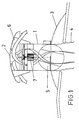
- Figure 1 shows the ventilation device, basically comprised of a cylindrical body (1) or ventilator neck, a spherical deflector (2) placed on the top and a hinged spherical base (3) on which is set the entire assembly and that is used for attachment to the roof. Also shown are the supports (6) to which is welded the spherical deflector (2).
- the cylindrical body (1) is the chimney in which the device draws the flow, which may be directly connected to the inside of the precinct or connected by means of a telescoping flexible duct (4) as shown in the figure.
- the motorised fan (7) Inside the cylindrical body (1) is the motorised fan (7) with its corresponding blades and the motorised window in charge of opening and closing the ventilator.
- Figure 2 in general shows the same parts described above, and reveals the supports (8) of the motorised fan (7) to the cylindrical body (1) and the tangential air exhaust with the aid of the supports (6) of the spherical deflector (2). Later on and in successive figures the constructive details of the assembly will be shown in greater detail.
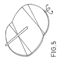
- Figures 3, 4 and 5 show the most remarkable characteristics of the motorised window (5), meant to open and close the air flue.
- the window (5) is shaped as a circle with a shaft across one of its diameters.
- Figure 4 shows the profile of the window (5) that is basically in the form of a wave so that when it is vertical it aids the formation of a spiral in the air. This shape provides advantages by stiffening the cover without requiring reinforcements to be welded on it, increasing the inertia in the rotation sense of the cover.
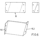
- Figures 6 and 7 show two possible embodiments for the supports (8) of the motorised fan (7) to the cylindrical body (1). As shown in figure 6 these have a Z-shape, while as shown in figure 7 they have a U-shape. In any case their ends have folds that define trapezoidal ends (8.1), (8.2), (8.3) and (8.4). Said supports (8) are placed turned with respect to the centre, forcing the air to move in a spiral towards the blade (9) of the fan, providing an increased performance an less noise.
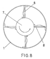
- Figure 8 shows in a broken line the tensions applied to the supports (8); said system of supports (8) reinforces the structure of the unit by improving the load distribution, and in addition has an almost zero inertia in the torsion sense of the motor, allowing a torsional motion of the support that favours the absorption by the motor of its own torsional vibrations in its motion. As the support system absorbs the vibrations it prevents them from being transmitted to the unit. In addition, and as it is placed perpendicular to the cylindrical body (1), it prevents load losses.
- Figures 9 to 11 shows various types of deflectors, all of them in the form of a spherical cap in a single piece, made of galvanised or stainless steel plate.
- Said deflector (2) has a minimised air resistance because of the shape of its surface, aids natural convection and prevents undesired turbulence.
- Figure 10 shows the deflector (2) with a backflow preventor (2.1) while figure 11 shows the backflow preventor (2.2) with a water-drop shape. These backflow preventors are meant to compensate the shadow of the blade core chosen.
- Figures 12 and 13 show the union of the cylindrical body (1) and the spherical base (3).
- Said spherical base has a flat area (3.1) for union to the roof and a central bulge in the form of a spherical cap, where an orifice is provided. SO that this orifice is valid regardless of the inclination of the roof, an endless circular cut is made from the centre of the cap to the greatest possible diameter.
- an uncovered part (11) (as shown in figure 13)
- a plate or part (10) that overlaps said sphere in the required surface.
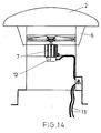
- Figure 14 shows the arrangement of the case (12) of the motorised fan (7), as set beneath the motor in order to reduce air resistance.
- the wiring (13) runs inside the cylindrical body (1) at all times, preventing its wear due to contact with the environment.
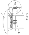
- Figure 15 shows, on the top edge of the cylindrical body (1), two parallel circular flanges (15) at the height of the blade (9), which provide an improved efficiency in extraction and impulsion while minimising the ovalisation of the cylinder and improving its performance by adjusting the window to the blade and reducing noise.
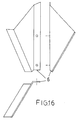
- figure 16 shows the supports (6) of the spherical deflector (2).
- Said supports (6) are made from folded plate and have a "Z" shape or the like, and are joined to the deflector (2) by welding.
- Figure 17 shows the air exhaust in a spiral inside the cylindrical body (1), ending tangentially with the aid of the supports (6) of the spherical deflector (2) and of the wind.
- the supports are regularly distributed and have an exit angle greater than 90°, allowing the spiral to end tangentially and protected from the wind pressure.
- the materials, shape, size and arrangement of the components may vary as long as the essence of the invention is not affected.
Abstract
Description
- The present invention relates to a ventilation device with spiral air channelling, from among industrial ventilation devices, preferably mounted on a roof.
- The present invention is characterised, among other factors, by enabling a spiral air extraction that facilitates extraction in a mixed manner, performed either dynamically with a blade driven by a motorised fan or by natural physical convection using thermal gradients of the air.
- Also the object of the invention are the physical and structural characteristics of the ventilation device, which in combination and when assembled together facilitate air extraction in a spiral, as well as providing a greater structural stiffness to withstand wind forces, resulting in an improved performance in general and a substantial noise reduction, reducing the transmitted vibrations.
- The present invention thus lies in the field of ventilators or air extraction equipment.
- Ventilation devices currently available in the market carry out the extraction either by Venturi systems or mixed systems, by convection with specific designs. In all prior solutions the ventilation devices are made from cut, folded and drilled plates, sewn by tubular rivets or surface screws on the top cone and on the base.
- In other cases the ventilation devices are made from a single piece with polyester resins, although this presents certain drawbacks as diameters above 500 mm are difficult to obtain due to the structural problems encountered when affected by the external temperatures that they may be subjected to.
- In addition, in order to avoid rainfall convection or motorised devices have cones with large diameters in relation to the chimney body, which hinders a correct suction in the case of convection.
- We also find that ventilation devices with envelopes significantly reduce performance, as they force the flow to turn 180°.
- As regards Venturi-based ventilation systems, these suffer from a serious drawback such as loss of pressure through their side openings, as these are used with a motor, while those devices that do not use a motor only reach an efficiency of 30% of the flow.
- A further difficulty encountered in currently available ventilation devices is the form of attachment to the roof, as this is normally performed in a bespoke fashion depending on the inclination of said roof, where the base used for attachment to the deck is comprised of several parts welded and riveted to each other. This solution does not ensure water tightness.
- It is also often the case that the means currently employed for securing the motor consist of metal plates attached as tie rods, the entire surface of which offer resistance to air passage, and in which the connection box is placed on the side, further increasing air resistance. Finally, it should be mentioned that devices as currently installed have the wiring outside the device, exposed to environmental hazards.
- Thus, the object of the present invention is to overcome the aforementioned drawbacks of ventilation devices, providing one that allows an improved adaptation and attachment of the structure of the ventilation device to the roof, prevents entry of rainwater, has a structure that is not made from cut, folded and drilled plate joined by riveting, has no pressure losses whatsoever and in which the entire unit is designed so that it offers a minimal air resistance and favours a spiral air channelling.
- The invention disclosed of a ventilation device with spiral air channelling consists of a device that performs a spiral air extraction in a gradual manner, suctioning air from the interior through a spherical shape, in which are involved the opening and closing window, the motor support fins, the blades of the motorised fan, the spherical deflector and its supports. With all of this a hurricane effect is achieved for the air motion that reduces load losses from residual turbulence and improves flow rates, as the air at all times operates with spherical, cylindrical or conical surface envelopes.
- The ventilation device object of the invention basically comprises a hinged spherical base, a spherical deflector, its tangential supports and a cylinder that is the body of the chimney.
- Both the hinged spherical base and the spherical deflector are curved surfaces, and thus provide the assembly with a greater structural stiffness that allows withstanding the wind force in any direction, as its air resistance is minimised. Both are made with galvanised metal or stainless steel plate and in a single piece, with no orifices, cuts or unions so that moisture or rain will not affect it in any manner and torsions, wear and oxidation are prevented.
- The spherical base is hinged so that it may adapt to the inclination of the deck. It has the shape of a spherical cap and is attached to the chimney body, a cylinder, at any point. The intersection between the two is circular and in the case of inclined roofs part of the surface of the spherical base may be uncovered. In order to cover this part of the spherical base a flap is provided on the base of the chimney to cover or overlap the exposed gap, so that no rain will enter the hinged spherical base. It is also possible to make an orifice at the exact point of union of the two parts and later weld them together.
- The cylindrical body or chimney is where the air is drawn, either directly from the inside of the precinct from which air must be extracted or through a telescoping and flexible tube.
- Inside the cylinder the motorised fan connection case and the window lid are installed, designed to channelling spiral air.
- The motorised window is in charge of opening and closing the air passage. It has a circular shape crossed by a shaft that makes it turn 90° when opening or closing. The window has a wavelike shape to aid the spiral air formation when air passes through it. This shape of the window provides it with a greater stiffness and increases its inertia in the rotation sense of the cover.
- The motorised fan is secured to the cylindrical body by a number of support points in the form of "Z" or "U''-shaped fins that are perpendicular to the motor and that are turned a certain angle from the centre of the motor, thus forcing the air to turn in a spiral. The design of these supports is such that the system has nearly no inertia in the torsion sense of the motor, allowing the motor to absorb torsional vibrations by its own motion and further preventing load losses as said attachments are positioned perpendicular to the rest of the cylindrical body.
- In addition, in order to favour air passage through the interior of the cylindrical body the motorised fan connection case instead of being placed lateral to said fan is placed below it. The wiring is also arranged so that it runs inside the cylinder at all times, with no wires exposed in order to prevent their wear due to environmental or accidental conditions.
- Furthermore, the upper neck of the chimney is provided with two parallel circular flanges at the height of the blade, in order to obtain a higher efficiency during extraction and impulsion, while minimising the ovalisation of the cylinder, as well as providing a constant flow rate by adjusting the aspiration opening to the blade.
- As regards the supports of the spherical deflector, these are crucial for redirecting the air into a spiral and are made from a plate folded into a " Z " or similar shape. The number of attachments provided will depend on the size of the device, the wind pressure to withstand and the higher-order harmonics of the ventilator. In order to prevent orifices in the deflector the attachments are welded to said deflector to form a single piece. They are screwed onto the cylindrical neck for purposes of cleaning and maintenance at a point protected from the rain.
- The spherical deflector is made from a shaping die or mould from a single piece of galvanised or stainless steel metal plate. As its shape is spherical it has a greater structural stiffness and as it has no cuts or unions it is not affected by humidity and environmental factors. Its shape gives it a reduced resistance to external air while aiding natural convection and preventing undesired turbulences for extraction of the internal air, while helping the distribution of the extracted air into equal parts. In addition, as its radius is progressive the air trajectory ends tangentially. This deflector does not require the use of a backflow preventor, thereby avoiding load losses and reducing vibrations.
- As an option it is possible to install a backflow preventor or an internal cone with absorbent materials to compensate the shadow of the blade core.
- As a complement of the description provided below and in order to aid a better understanding of the characteristics of the invention the present descriptive memory is accompanied by a set of drawings with figures where for purposes of illustration and in a non-limiting sense the most relevant details of the invention are shown.
- Figure 1 shows a sectional view along the entire length of the assembled unit.
- Figure 2 shows a plan view of the unit.
- Figure 3 shows a representation of the ventilator unit with the window vertical.
- Figure 4 shows the same as the previous figure, with the window placed horizontally.
- Figure 5 shows the window in a perspective view.
- Figure 6 shows an example of an embodiment for the motor supports.
- Figure 7 shows another example of embodiment for the motor supports.
- Figure 8 shows the arrangement of the motor supports between the cylinder and the motor itself.
- Figures 9, 10 and 11 shows various examples of embodiments for the backflow preventor.
- Figure 12 shows the union between the cylinder and the hinged spherical base.
- Figure 13 shows the same as the previous figure for the case with a slightly inclined roof.
- Figure 14 shows the form of connection of the motor.
- Figure 15 shows the flanges at the top end of the cylinder.
- Figure 16 shows the form of the supports for the spherical deflector.
- Figure 17 shows the effect of the spherical deflector supports with the air exhaust and the wind.
- In view of the figures a description of a preferred embodiment of the invention is provided below, as well as a description of the figures.
- Figure 1 shows the ventilation device, basically comprised of a cylindrical body (1) or ventilator neck, a spherical deflector (2) placed on the top and a hinged spherical base (3) on which is set the entire assembly and that is used for attachment to the roof. Also shown are the supports (6) to which is welded the spherical deflector (2). The cylindrical body (1) is the chimney in which the device draws the flow, which may be directly connected to the inside of the precinct or connected by means of a telescoping flexible duct (4) as shown in the figure.
- Inside the cylindrical body (1) is the motorised fan (7) with its corresponding blades and the motorised window in charge of opening and closing the ventilator.
- Figure 2 in general shows the same parts described above, and reveals the supports (8) of the motorised fan (7) to the cylindrical body (1) and the tangential air exhaust with the aid of the supports (6) of the spherical deflector (2). Later on and in successive figures the constructive details of the assembly will be shown in greater detail.
- Figures 3, 4 and 5 show the most remarkable characteristics of the motorised window (5), meant to open and close the air flue. Basically, the window (5) is shaped as a circle with a shaft across one of its diameters. Figure 4 shows the profile of the window (5) that is basically in the form of a wave so that when it is vertical it aids the formation of a spiral in the air. This shape provides advantages by stiffening the cover without requiring reinforcements to be welded on it, increasing the inertia in the rotation sense of the cover.
- Figures 6 and 7 show two possible embodiments for the supports (8) of the motorised fan (7) to the cylindrical body (1). As shown in figure 6 these have a Z-shape, while as shown in figure 7 they have a U-shape. In any case their ends have folds that define trapezoidal ends (8.1), (8.2), (8.3) and (8.4). Said supports (8) are placed turned with respect to the centre, forcing the air to move in a spiral towards the blade (9) of the fan, providing an increased performance an less noise.
- Figure 8 shows in a broken line the tensions applied to the supports (8); said system of supports (8) reinforces the structure of the unit by improving the load distribution, and in addition has an almost zero inertia in the torsion sense of the motor, allowing a torsional motion of the support that favours the absorption by the motor of its own torsional vibrations in its motion. As the support system absorbs the vibrations it prevents them from being transmitted to the unit. In addition, and as it is placed perpendicular to the cylindrical body (1), it prevents load losses.
- Figures 9 to 11 shows various types of deflectors, all of them in the form of a spherical cap in a single piece, made of galvanised or stainless steel plate. Said deflector (2) has a minimised air resistance because of the shape of its surface, aids natural convection and prevents undesired turbulence.
- Figure 10 shows the deflector (2) with a backflow preventor (2.1) while figure 11 shows the backflow preventor (2.2) with a water-drop shape. These backflow preventors are meant to compensate the shadow of the blade core chosen.
- Figures 12 and 13 show the union of the cylindrical body (1) and the spherical base (3). Said spherical base has a flat area (3.1) for union to the roof and a central bulge in the form of a spherical cap, where an orifice is provided. SO that this orifice is valid regardless of the inclination of the roof, an endless circular cut is made from the centre of the cap to the greatest possible diameter. As the union between the cylindrical body (1) and the spherical base (3) leaves an uncovered part (11) (as shown in figure 13), on the bottom of the cylindrical body (1) is welded a plate or part (10) that overlaps said sphere in the required surface.
- Figure 14 shows the arrangement of the case (12) of the motorised fan (7), as set beneath the motor in order to reduce air resistance. In addition the wiring (13) runs inside the cylindrical body (1) at all times, preventing its wear due to contact with the environment.
- Figure 15 shows, on the top edge of the cylindrical body (1), two parallel circular flanges (15) at the height of the blade (9), which provide an improved efficiency in extraction and impulsion while minimising the ovalisation of the cylinder and improving its performance by adjusting the window to the blade and reducing noise.
- Finally, figure 16 shows the supports (6) of the spherical deflector (2). Said supports (6) are made from folded plate and have a "Z" shape or the like, and are joined to the deflector (2) by welding.
- Figure 17 shows the air exhaust in a spiral inside the cylindrical body (1), ending tangentially with the aid of the supports (6) of the spherical deflector (2) and of the wind.
- It should be noted that the supports are regularly distributed and have an exit angle greater than 90°, allowing the spiral to end tangentially and protected from the wind pressure.
- It is not considered necessary to extend this description in order for an expert in the field to understand the scope of the invention and the advantages derived thereof.
- The materials, shape, size and arrangement of the components may vary as long as the essence of the invention is not affected.
- The terms used in this memory should be understood in a wide and non-limiting sense.
Claims (12)
- Ventilation device with spiral air channelling characterised in that it facilitates air extraction in a spiral, whether in a mixed manner, dynamically with a motorised fan blade or by physical convection of a thermal origin, with the air forced to exit the ventilator device tangentially, for which purpose the device is provided with a base (3) and a deflector (2), both spherical, without orifices nor cuts, made of galvanised or stainless steel plate, and is further provided with a chimney defined by a cylindrical body (1) inside which are housed the motorised fan (7) and the motorised window (5).
- Ventilation device with spiral air channelling according to claim 1, characterised in that the spherical base (3) is hinged to the inclination of the roof, for which it is provided with a flat peripheral flap (3.1) that allows attaching said base to the roof, while on the part in the form of a spherical cap an endless circular cut is provided so that it does not have to be shortened for each inclination of the roof.
- Ventilation device with spiral air channelling according to claim 2, characterised in that in order to cover the uncovered part (11) between the cylindrical body (1) and the spherical base (3) a part or flap (11) is provided on the bottom end of the cylindrical body (1).
- Ventilation device with spiral air channelling according to claim 1, characterised in that the motorised window (5) has a circular shape crossed by a diametric shaft, and a profile with a wavelike shape.
- Ventilation device with spiral air channelling according to claim 1, characterised in that the attachment of the motorised fan (7) to the cylindrical body (1) Z-shaped supports (8) with their ends folded to define trapezoidal surfaces (8.1) and (8.2).
- Ventilation device with spiral air channelling according to claim 1, characterised in that the attachment of the motorised fan (7) to the cylindrical body (1) is effected by U-shaped supports (8) with their ends folded to define trapezoidal surfaces (8.3) and (8.4).
- Ventilation device with spiral air channelling according to claim 1, characterised in that the motorised fan (7) has its connection case (12) installed beneath it.
- Ventilation device with spiral air channelling according to claim 1, characterised in that the wiring (13) that reaches the connection case (12) of the motorised fan (7) runs inside the device.
- Ventilation device with spiral air channelling according to claim 1, characterised in that the top part of the cylindrical body (1) is provided with two circular, parallel flanges (14) at the height of the blade (9).
- Ventilation device with spiral air channelling according to claim 1, characterised in that the supports of the spherical deflector (2) have a "Z" or similar shape that helps the spiral formation of the air and its tangential exhaust; these supports (6) are joined to the spherical deflector by welding and are distributed regularly with an exit angle greater than 90°, thereby allowing the spiral air formation to end tangentially.
- Ventilation device with spiral air channelling according to claim 1, characterised in that the spherical deflector (2) is provided with a backflow preventor (2.1) to compensate the shadow of the core of the chosen blade.
- Ventilation device with spiral air channelling according to claim 1, characterised in that the spherical deflector (2) is provided with a backflow preventor (2.2) to compensate the shadow of the core of the chosen blade.
Priority Applications (5)
| Application Number | Priority Date | Filing Date | Title |
|---|---|---|---|
| EP02380112A EP1367335B1 (en) | 2002-05-28 | 2002-05-28 | Ventilation device with spiral air channelling |
| DE60221106T DE60221106D1 (en) | 2002-05-28 | 2002-05-28 | Ventilation system with spiral guide |
| AT02380112T ATE366898T1 (en) | 2002-05-28 | 2002-05-28 | VENTILATION SYSTEM WITH SPIRAL-SHAPED GUIDE DEVICE |
| ES02380112T ES2289070T3 (en) | 2002-05-28 | 2002-05-28 | VENTILATION DEVICE WITH SPIRAL AIR CHANNELING. |
| PT02380112T PT1367335E (en) | 2002-05-28 | 2002-05-28 | Ventilation device with spiral air channelling |
Applications Claiming Priority (1)
| Application Number | Priority Date | Filing Date | Title |
|---|---|---|---|
| EP02380112A EP1367335B1 (en) | 2002-05-28 | 2002-05-28 | Ventilation device with spiral air channelling |
Publications (2)
| Publication Number | Publication Date |
|---|---|
| EP1367335A1 true EP1367335A1 (en) | 2003-12-03 |
| EP1367335B1 EP1367335B1 (en) | 2007-07-11 |
Family
ID=29414845
Family Applications (1)
| Application Number | Title | Priority Date | Filing Date |
|---|---|---|---|
| EP02380112A Expired - Lifetime EP1367335B1 (en) | 2002-05-28 | 2002-05-28 | Ventilation device with spiral air channelling |
Country Status (5)
| Country | Link |
|---|---|
| EP (1) | EP1367335B1 (en) |
| AT (1) | ATE366898T1 (en) |
| DE (1) | DE60221106D1 (en) |
| ES (1) | ES2289070T3 (en) |
| PT (1) | PT1367335E (en) |
Cited By (5)
| Publication number | Priority date | Publication date | Assignee | Title |
|---|---|---|---|---|
| NL2001219C2 (en) * | 2008-01-25 | 2009-07-30 | Ubbink Bv | Roof terminal for ventilation through roof of building, has connecting piece with base part for installation on roof, and axial fan driven by electric motor, where electric motor is connected to rigid handle shaft of axial fan |
| RU2475683C1 (en) * | 2011-08-03 | 2013-02-20 | Федеральное государственное бюджетное образовательное учреждение высшего профессионального образования "Орловский государственный аграрный университет" (ФГБОУ ВПО Орел ГАУ) | Deflector for exhaust ventilation pipe |
| RU2637353C1 (en) * | 2016-08-25 | 2017-12-04 | Артём Васильевич Нестеров | Exhaust pipe deflector by nesterov |
| CN109520064A (en) * | 2018-11-27 | 2019-03-26 | 山东中恒建设集团有限公司 | A kind of temporary building room ventilation device |
| CN113316689A (en) * | 2019-01-30 | 2021-08-27 | 株式会社不二工机 | Rotary blade for drain pump and drain pump with same |
Citations (6)
| Publication number | Priority date | Publication date | Assignee | Title |
|---|---|---|---|---|
| GB865730A (en) * | 1958-10-28 | 1961-04-19 | Colt Ventilation Ltd | Improvements in upward discharge ventilators |
| US3952638A (en) * | 1975-03-10 | 1976-04-27 | Felter John V | Fans for use with turbine ventilators, and methods and apparatus for supporting the same |
| US4370876A (en) * | 1978-12-11 | 1983-02-01 | Ballard James W | Methods of constructing a one-piece roof vent device |
| EP0802378A2 (en) * | 1996-04-20 | 1997-10-22 | Johannes Klöber | Venting device |
| DE19921069C1 (en) * | 1999-05-07 | 2000-10-05 | Lafarge Braas Roofing Accessor | Roof ventilator is fixed in position by two ratchet locks at the cup and pan and at the joint axis for a simple mounting and adjustment without skills in a simple and robust assembly |
| US20010039776A1 (en) * | 1992-08-04 | 2001-11-15 | O'hagin Harry | Attic vent with a one-piece, fitted skeleton |
-
2002
- 2002-05-28 DE DE60221106T patent/DE60221106D1/en not_active Expired - Lifetime
- 2002-05-28 ES ES02380112T patent/ES2289070T3/en not_active Expired - Lifetime
- 2002-05-28 AT AT02380112T patent/ATE366898T1/en not_active IP Right Cessation
- 2002-05-28 PT PT02380112T patent/PT1367335E/en unknown
- 2002-05-28 EP EP02380112A patent/EP1367335B1/en not_active Expired - Lifetime
Patent Citations (6)
| Publication number | Priority date | Publication date | Assignee | Title |
|---|---|---|---|---|
| GB865730A (en) * | 1958-10-28 | 1961-04-19 | Colt Ventilation Ltd | Improvements in upward discharge ventilators |
| US3952638A (en) * | 1975-03-10 | 1976-04-27 | Felter John V | Fans for use with turbine ventilators, and methods and apparatus for supporting the same |
| US4370876A (en) * | 1978-12-11 | 1983-02-01 | Ballard James W | Methods of constructing a one-piece roof vent device |
| US20010039776A1 (en) * | 1992-08-04 | 2001-11-15 | O'hagin Harry | Attic vent with a one-piece, fitted skeleton |
| EP0802378A2 (en) * | 1996-04-20 | 1997-10-22 | Johannes Klöber | Venting device |
| DE19921069C1 (en) * | 1999-05-07 | 2000-10-05 | Lafarge Braas Roofing Accessor | Roof ventilator is fixed in position by two ratchet locks at the cup and pan and at the joint axis for a simple mounting and adjustment without skills in a simple and robust assembly |
Cited By (7)
| Publication number | Priority date | Publication date | Assignee | Title |
|---|---|---|---|---|
| NL2001219C2 (en) * | 2008-01-25 | 2009-07-30 | Ubbink Bv | Roof terminal for ventilation through roof of building, has connecting piece with base part for installation on roof, and axial fan driven by electric motor, where electric motor is connected to rigid handle shaft of axial fan |
| RU2475683C1 (en) * | 2011-08-03 | 2013-02-20 | Федеральное государственное бюджетное образовательное учреждение высшего профессионального образования "Орловский государственный аграрный университет" (ФГБОУ ВПО Орел ГАУ) | Deflector for exhaust ventilation pipe |
| RU2637353C1 (en) * | 2016-08-25 | 2017-12-04 | Артём Васильевич Нестеров | Exhaust pipe deflector by nesterov |
| CN109520064A (en) * | 2018-11-27 | 2019-03-26 | 山东中恒建设集团有限公司 | A kind of temporary building room ventilation device |
| CN109520064B (en) * | 2018-11-27 | 2023-06-23 | 山东中恒建设集团有限公司 | Temporary building room ventilation device |
| CN113316689A (en) * | 2019-01-30 | 2021-08-27 | 株式会社不二工机 | Rotary blade for drain pump and drain pump with same |
| CN113316689B (en) * | 2019-01-30 | 2023-09-08 | 株式会社不二工机 | Rotary vane for drainage pump and drainage pump with same |
Also Published As
| Publication number | Publication date |
|---|---|
| ES2289070T3 (en) | 2008-02-01 |
| PT1367335E (en) | 2007-09-18 |
| DE60221106D1 (en) | 2007-08-23 |
| ATE366898T1 (en) | 2007-08-15 |
| EP1367335B1 (en) | 2007-07-11 |
Similar Documents
| Publication | Publication Date | Title |
|---|---|---|
| CN111819400B (en) | Unpowered ventilation part | |
| US7241214B2 (en) | Upblast fan nozzle with wind deflecting panels | |
| US5050489A (en) | Roof ventilator | |
| EP1367335B1 (en) | Ventilation device with spiral air channelling | |
| US4000688A (en) | Ventilator for roof ridge | |
| US6202372B1 (en) | Off-ridge roof vent | |
| US9664399B2 (en) | Ventilator and blade therefor | |
| AU2013313031A1 (en) | Rotor ventilator | |
| US3412670A (en) | Roof ventilator | |
| US2232027A (en) | Ventilator | |
| CN103015599A (en) | Thin roof daylighting ventilator | |
| EP0939878B1 (en) | Static venting system | |
| US2492242A (en) | Ventilating apparatus | |
| JP2936999B2 (en) | Ventilation ventilator | |
| US1783406A (en) | Ventilator | |
| US2824507A (en) | Roof ventilators | |
| CN220417531U (en) | Air-pulling hood | |
| RU212565U1 (en) | Roof Ventilation Umbrella | |
| KR102611669B1 (en) | Ventilation apparatus for building duct | |
| JP2008215743A (en) | External wall terminal ventilation opening | |
| US3309979A (en) | Ventilating device | |
| CN219711635U (en) | Exhaust tail pipe capable of preventing water from entering after treatment | |
| US1611005A (en) | Ventilator | |
| JPH07269917A (en) | Ventilator | |
| CN217300969U (en) | Roof fan |
Legal Events
| Date | Code | Title | Description |
|---|---|---|---|
| PUAI | Public reference made under article 153(3) epc to a published international application that has entered the european phase |
Free format text: ORIGINAL CODE: 0009012 |
|
| AK | Designated contracting states |
Kind code of ref document: A1 Designated state(s): AT BE CH CY DE DK ES FI FR GB GR IE IT LI LU MC NL PT SE TR |
|
| AX | Request for extension of the european patent |
Extension state: AL LT LV MK RO SI |
|
| 17P | Request for examination filed |
Effective date: 20040130 |
|
| RAP1 | Party data changed (applicant data changed or rights of an application transferred) |
Owner name: BATLLE COLLET, JOAN |
|
| AKX | Designation fees paid |
Designated state(s): AT BE CH CY DE DK ES FI FR GB GR IE IT LI LU MC NL PT SE TR |
|
| 17Q | First examination report despatched |
Effective date: 20060927 |
|
| GRAP | Despatch of communication of intention to grant a patent |
Free format text: ORIGINAL CODE: EPIDOSNIGR1 |
|
| RIN1 | Information on inventor provided before grant (corrected) |
Inventor name: CANYADELL BADENES, JOSEP Inventor name: VALLESPIN MEJIAS, JAIME Inventor name: BATLLE COLLET, JOAN |
|
| GRAS | Grant fee paid |
Free format text: ORIGINAL CODE: EPIDOSNIGR3 |
|
| GRAA | (expected) grant |
Free format text: ORIGINAL CODE: 0009210 |
|
| AK | Designated contracting states |
Kind code of ref document: B1 Designated state(s): AT BE CH CY DE DK ES FI FR GB GR IE IT LI LU MC NL PT SE TR |
|
| REG | Reference to a national code |
Ref country code: GB Ref legal event code: FG4D |
|
| REG | Reference to a national code |
Ref country code: CH Ref legal event code: EP |
|
| REF | Corresponds to: |
Ref document number: 60221106 Country of ref document: DE Date of ref document: 20070823 Kind code of ref document: P |
|
| REG | Reference to a national code |
Ref country code: IE Ref legal event code: FG4D |
|
| REG | Reference to a national code |
Ref country code: PT Ref legal event code: SC4A Free format text: AVAILABILITY OF NATIONAL TRANSLATION Effective date: 20070906 |
|
| ET | Fr: translation filed | ||
| PG25 | Lapsed in a contracting state [announced via postgrant information from national office to epo] |
Ref country code: FI Free format text: LAPSE BECAUSE OF FAILURE TO SUBMIT A TRANSLATION OF THE DESCRIPTION OR TO PAY THE FEE WITHIN THE PRESCRIBED TIME-LIMIT Effective date: 20070711 Ref country code: NL Free format text: LAPSE BECAUSE OF FAILURE TO SUBMIT A TRANSLATION OF THE DESCRIPTION OR TO PAY THE FEE WITHIN THE PRESCRIBED TIME-LIMIT Effective date: 20070711 |
|
| REG | Reference to a national code |
Ref country code: CH Ref legal event code: PL |
|
| NLV1 | Nl: lapsed or annulled due to failure to fulfill the requirements of art. 29p and 29m of the patents act | ||
| REG | Reference to a national code |
Ref country code: ES Ref legal event code: FG2A Ref document number: 2289070 Country of ref document: ES Kind code of ref document: T3 |
|
| PG25 | Lapsed in a contracting state [announced via postgrant information from national office to epo] |
Ref country code: LI Free format text: LAPSE BECAUSE OF FAILURE TO SUBMIT A TRANSLATION OF THE DESCRIPTION OR TO PAY THE FEE WITHIN THE PRESCRIBED TIME-LIMIT Effective date: 20070711 Ref country code: AT Free format text: LAPSE BECAUSE OF FAILURE TO SUBMIT A TRANSLATION OF THE DESCRIPTION OR TO PAY THE FEE WITHIN THE PRESCRIBED TIME-LIMIT Effective date: 20070711 Ref country code: CH Free format text: LAPSE BECAUSE OF FAILURE TO SUBMIT A TRANSLATION OF THE DESCRIPTION OR TO PAY THE FEE WITHIN THE PRESCRIBED TIME-LIMIT Effective date: 20070711 |
|
| PG25 | Lapsed in a contracting state [announced via postgrant information from national office to epo] |
Ref country code: BE Free format text: LAPSE BECAUSE OF FAILURE TO SUBMIT A TRANSLATION OF THE DESCRIPTION OR TO PAY THE FEE WITHIN THE PRESCRIBED TIME-LIMIT Effective date: 20070711 |
|
| PG25 | Lapsed in a contracting state [announced via postgrant information from national office to epo] |
Ref country code: DK Free format text: LAPSE BECAUSE OF FAILURE TO SUBMIT A TRANSLATION OF THE DESCRIPTION OR TO PAY THE FEE WITHIN THE PRESCRIBED TIME-LIMIT Effective date: 20070711 Ref country code: GR Free format text: LAPSE BECAUSE OF FAILURE TO SUBMIT A TRANSLATION OF THE DESCRIPTION OR TO PAY THE FEE WITHIN THE PRESCRIBED TIME-LIMIT Effective date: 20071012 |
|
| PLBE | No opposition filed within time limit |
Free format text: ORIGINAL CODE: 0009261 |
|
| STAA | Information on the status of an ep patent application or granted ep patent |
Free format text: STATUS: NO OPPOSITION FILED WITHIN TIME LIMIT |
|
| 26N | No opposition filed |
Effective date: 20080414 |
|
| PG25 | Lapsed in a contracting state [announced via postgrant information from national office to epo] |
Ref country code: SE Free format text: LAPSE BECAUSE OF FAILURE TO SUBMIT A TRANSLATION OF THE DESCRIPTION OR TO PAY THE FEE WITHIN THE PRESCRIBED TIME-LIMIT Effective date: 20071011 |
|
| PG25 | Lapsed in a contracting state [announced via postgrant information from national office to epo] |
Ref country code: DE Free format text: LAPSE BECAUSE OF FAILURE TO SUBMIT A TRANSLATION OF THE DESCRIPTION OR TO PAY THE FEE WITHIN THE PRESCRIBED TIME-LIMIT Effective date: 20071012 |
|
| PG25 | Lapsed in a contracting state [announced via postgrant information from national office to epo] |
Ref country code: MC Free format text: LAPSE BECAUSE OF NON-PAYMENT OF DUE FEES Effective date: 20080531 |
|
| GBPC | Gb: european patent ceased through non-payment of renewal fee |
Effective date: 20080528 |
|
| PG25 | Lapsed in a contracting state [announced via postgrant information from national office to epo] |
Ref country code: IE Free format text: LAPSE BECAUSE OF NON-PAYMENT OF DUE FEES Effective date: 20080528 |
|
| PGFP | Annual fee paid to national office [announced via postgrant information from national office to epo] |
Ref country code: PT Payment date: 20090325 Year of fee payment: 8 |
|
| PG25 | Lapsed in a contracting state [announced via postgrant information from national office to epo] |
Ref country code: GB Free format text: LAPSE BECAUSE OF NON-PAYMENT OF DUE FEES Effective date: 20080528 |
|
| PG25 | Lapsed in a contracting state [announced via postgrant information from national office to epo] |
Ref country code: CY Free format text: LAPSE BECAUSE OF FAILURE TO SUBMIT A TRANSLATION OF THE DESCRIPTION OR TO PAY THE FEE WITHIN THE PRESCRIBED TIME-LIMIT Effective date: 20070711 |
|
| PG25 | Lapsed in a contracting state [announced via postgrant information from national office to epo] |
Ref country code: IT Free format text: LAPSE BECAUSE OF NON-PAYMENT OF DUE FEES Effective date: 20080528 |
|
| PG25 | Lapsed in a contracting state [announced via postgrant information from national office to epo] |
Ref country code: LU Free format text: LAPSE BECAUSE OF NON-PAYMENT OF DUE FEES Effective date: 20080528 |
|
| PGFP | Annual fee paid to national office [announced via postgrant information from national office to epo] |
Ref country code: FR Payment date: 20100416 Year of fee payment: 9 |
|
| PG25 | Lapsed in a contracting state [announced via postgrant information from national office to epo] |
Ref country code: TR Free format text: LAPSE BECAUSE OF FAILURE TO SUBMIT A TRANSLATION OF THE DESCRIPTION OR TO PAY THE FEE WITHIN THE PRESCRIBED TIME-LIMIT Effective date: 20070711 |
|
| REG | Reference to a national code |
Ref country code: PT Ref legal event code: MM4A Free format text: LAPSE DUE TO NON-PAYMENT OF FEES Effective date: 20101129 |
|
| PG25 | Lapsed in a contracting state [announced via postgrant information from national office to epo] |
Ref country code: PT Free format text: LAPSE BECAUSE OF NON-PAYMENT OF DUE FEES Effective date: 20101129 |
|
| PGFP | Annual fee paid to national office [announced via postgrant information from national office to epo] |
Ref country code: IT Payment date: 20090506 Year of fee payment: 8 |
|
| PGRI | Patent reinstated in contracting state [announced from national office to epo] |
Ref country code: IT Effective date: 20110616 |
|
| REG | Reference to a national code |
Ref country code: FR Ref legal event code: ST Effective date: 20120131 |
|
| PG25 | Lapsed in a contracting state [announced via postgrant information from national office to epo] |
Ref country code: FR Free format text: LAPSE BECAUSE OF NON-PAYMENT OF DUE FEES Effective date: 20110531 |
|
| PGRI | Patent reinstated in contracting state [announced from national office to epo] |
Ref country code: IT Effective date: 20110616 |
|
| PGFP | Annual fee paid to national office [announced via postgrant information from national office to epo] |
Ref country code: ES Payment date: 20210701 Year of fee payment: 20 |
|
| REG | Reference to a national code |
Ref country code: ES Ref legal event code: FD2A Effective date: 20220706 |
|
| PG25 | Lapsed in a contracting state [announced via postgrant information from national office to epo] |
Ref country code: ES Free format text: LAPSE BECAUSE OF EXPIRATION OF PROTECTION Effective date: 20220529 |