EP1367247B1 - Méthode de contrôle d'un moteur à combustion interne - Google Patents
Méthode de contrôle d'un moteur à combustion interne Download PDFInfo
- Publication number
- EP1367247B1 EP1367247B1 EP02445067A EP02445067A EP1367247B1 EP 1367247 B1 EP1367247 B1 EP 1367247B1 EP 02445067 A EP02445067 A EP 02445067A EP 02445067 A EP02445067 A EP 02445067A EP 1367247 B1 EP1367247 B1 EP 1367247B1
- Authority
- EP
- European Patent Office
- Prior art keywords
- air
- engine
- fuel ratio
- fuel
- idling speed
- Prior art date
- Legal status (The legal status is an assumption and is not a legal conclusion. Google has not performed a legal analysis and makes no representation as to the accuracy of the status listed.)
- Expired - Lifetime
Links
Images

Classifications
-
- F—MECHANICAL ENGINEERING; LIGHTING; HEATING; WEAPONS; BLASTING
- F02—COMBUSTION ENGINES; HOT-GAS OR COMBUSTION-PRODUCT ENGINE PLANTS
- F02D—CONTROLLING COMBUSTION ENGINES
- F02D41/00—Electrical control of supply of combustible mixture or its constituents
- F02D41/02—Circuit arrangements for generating control signals
- F02D41/04—Introducing corrections for particular operating conditions
- F02D41/06—Introducing corrections for particular operating conditions for engine starting or warming up
- F02D41/062—Introducing corrections for particular operating conditions for engine starting or warming up for starting
- F02D41/064—Introducing corrections for particular operating conditions for engine starting or warming up for starting at cold start
-
- F—MECHANICAL ENGINEERING; LIGHTING; HEATING; WEAPONS; BLASTING
- F02—COMBUSTION ENGINES; HOT-GAS OR COMBUSTION-PRODUCT ENGINE PLANTS
- F02D—CONTROLLING COMBUSTION ENGINES
- F02D31/00—Use of speed-sensing governors to control combustion engines, not otherwise provided for
- F02D31/001—Electric control of rotation speed
- F02D31/002—Electric control of rotation speed controlling air supply
- F02D31/003—Electric control of rotation speed controlling air supply for idle speed control
-
- F—MECHANICAL ENGINEERING; LIGHTING; HEATING; WEAPONS; BLASTING
- F02—COMBUSTION ENGINES; HOT-GAS OR COMBUSTION-PRODUCT ENGINE PLANTS
- F02D—CONTROLLING COMBUSTION ENGINES
- F02D41/00—Electrical control of supply of combustible mixture or its constituents
- F02D41/02—Circuit arrangements for generating control signals
- F02D41/04—Introducing corrections for particular operating conditions
- F02D41/06—Introducing corrections for particular operating conditions for engine starting or warming up
- F02D41/062—Introducing corrections for particular operating conditions for engine starting or warming up for starting
-
- F—MECHANICAL ENGINEERING; LIGHTING; HEATING; WEAPONS; BLASTING
- F02—COMBUSTION ENGINES; HOT-GAS OR COMBUSTION-PRODUCT ENGINE PLANTS
- F02D—CONTROLLING COMBUSTION ENGINES
- F02D41/00—Electrical control of supply of combustible mixture or its constituents
- F02D41/02—Circuit arrangements for generating control signals
- F02D41/14—Introducing closed-loop corrections
- F02D41/16—Introducing closed-loop corrections for idling
-
- F—MECHANICAL ENGINEERING; LIGHTING; HEATING; WEAPONS; BLASTING
- F02—COMBUSTION ENGINES; HOT-GAS OR COMBUSTION-PRODUCT ENGINE PLANTS
- F02D—CONTROLLING COMBUSTION ENGINES
- F02D2200/00—Input parameters for engine control
- F02D2200/02—Input parameters for engine control the parameters being related to the engine
- F02D2200/04—Engine intake system parameters
- F02D2200/0414—Air temperature
-
- F—MECHANICAL ENGINEERING; LIGHTING; HEATING; WEAPONS; BLASTING
- F02—COMBUSTION ENGINES; HOT-GAS OR COMBUSTION-PRODUCT ENGINE PLANTS
- F02D—CONTROLLING COMBUSTION ENGINES
- F02D41/00—Electrical control of supply of combustible mixture or its constituents
- F02D41/02—Circuit arrangements for generating control signals
- F02D41/14—Introducing closed-loop corrections
- F02D41/1438—Introducing closed-loop corrections using means for determining characteristics of the combustion gases; Sensors therefor
- F02D41/1444—Introducing closed-loop corrections using means for determining characteristics of the combustion gases; Sensors therefor characterised by the characteristics of the combustion gases
- F02D41/1446—Introducing closed-loop corrections using means for determining characteristics of the combustion gases; Sensors therefor characterised by the characteristics of the combustion gases the characteristics being exhaust temperatures
-
- F—MECHANICAL ENGINEERING; LIGHTING; HEATING; WEAPONS; BLASTING
- F02—COMBUSTION ENGINES; HOT-GAS OR COMBUSTION-PRODUCT ENGINE PLANTS
- F02D—CONTROLLING COMBUSTION ENGINES
- F02D41/00—Electrical control of supply of combustible mixture or its constituents
- F02D41/02—Circuit arrangements for generating control signals
- F02D41/14—Introducing closed-loop corrections
- F02D41/1438—Introducing closed-loop corrections using means for determining characteristics of the combustion gases; Sensors therefor
- F02D41/1444—Introducing closed-loop corrections using means for determining characteristics of the combustion gases; Sensors therefor characterised by the characteristics of the combustion gases
- F02D41/1454—Introducing closed-loop corrections using means for determining characteristics of the combustion gases; Sensors therefor characterised by the characteristics of the combustion gases the characteristics being an oxygen content or concentration or the air-fuel ratio
Definitions
- the invention relates to a method and an arrangement for controlling the idling speed of a combustion engine.
- the invention allows the idling speed to vary as a function of the air/fuel ratio immediately after the engine is started.
- the standard way to solve the problem is to enrich the air/fuel ratio to the extent that most variations in volatility lie within the drivability limits.
- Such air/fuel ratios will have a rich air factor ⁇ in the range of 0,7-0,9, By definition, an air factor ⁇ less than 1 is termed “rich”, while a value greater than 1 is termed “lean”.
- the idling speed is conventionally controlled by adjusting the throttle and/or the ignition timing.
- the idling speed is set too high in a conventional combustion engine the fuel consumption, and consequently the exhaust emissions, will increase. The driver might also react to the increased noise from the engine. For vehicles with an automatic transmission it causes a noticeable jerking initial movement when the first or reverse gear engages.
- the idling speed is set too low, drivability is affected. Even a small fluctuation in engine stability may cause the engine to misfire, or to stall. The reduced amount of fuel will also increase the time taken for the engine to heat up, which directly affects the time required for the catalytic converter to reach its operating, or "light-off" temperature.
- the engine idling speed is commonly locked to a predetermined value, which a central processing unit (CPU) is mapped to maintain at all times.
- CPU central processing unit
- the air factor ⁇ set at "rich”, as described above, the CPU uses the throttle and/or the ignition timing to maintain the required idling speed.
- US 5 954 025 discloses a vehicle with a dual fuel system having a stability detector. This arrangement determines that instability occurs when the engine speed drops below a reference speed, whereby the air/fuel ratio is adjusted.
- the invention allows variations of the idling speed caused by varying fuel volatility during normal operation, but is not suitable for use with a lean start strategy.
- US 2002/43247-A1 discloses a control system for an internal combustion engine in which a fuel supply control unit estimates an A/F ratio based on the engine speed and controls the A/F ratio immediately after start-up based on this estimated A/F ratio. In this case, the engine speed, or load, is used to estimate an A/F ratio.
- the invention relates to a method and an arrangement for controlling the idling speed of a combustion engine.
- the invention allows the idling speed to vary as a function of the difference between a target and an actual air/fuel ratio immediately after the engine is started. This is achieved by means of a method and an arrangement, the characteristics of which are disclosed in accompanying claims 1 and 9 and their respective dependent claims.
- the method involves the control of an internal combustion engine during a cold start operation, whereby the engine is operated using a lean actual air/fuel ratio when the engine is started, and that the engine has an idling speed that is allowed to vary as a function of the difference between a target air/fuel ratio and the actual air/fuel ratio.
- the target air/fuel ratio is that of the air-fuel mixture in the intake conduit
- the actual air/fuel ratio is that of the air-fuel mixture in the combustion chamber.
- the difference between a target and an actual air/fuel ratio may, for instance, be caused by variations in the fuel properties and/or wetting of the walls of the intake conduit.
- the throttle is kept at a substantially fixed opening angle while the fuel supply is adjusted towards a predetermined lean actual air/fuel ratio, with an actual air factor ⁇ T between 1,02 ⁇ ⁇ T ⁇ 1,2.
- This air/fuel ratio is maintained at a substantially constant value while the idling speed is allowed to vary.
- the idling speed of the engine will vary accordingly. This is due to the fact that the oxygen content of the induction air determines the possible maximum supply of energy, that is the amount of fuel that is theoretically possible to burn per combustion cycle of the engine.
- This operation can be carried out using a substantially constant throttle angle.
- the idling speed is allowed to drop. This reduces the internal friction at the same time as the flow rate of induction air per stroke increases briefly, due to the increased intake pressure caused by the drop in engine speed, giving a higher torque output.
- the engine will subsequently stabilise at a lower idling speed with a maintained, substantially constant actual air/fuel ratio.
- the operation can be further controlled by means of a basic calibration of the air-fuel mixture, performed to give a nominal idling speed.
- This calibration causes the air/fuel ratio to be enriched when a reduction in idling speed is detected, and the ratio to be made leaner when an increase in idling speed is detected.
- the purpose of the invention is to keep the actual air factor within a lean combustible range of 1,0 ⁇ ⁇ A ⁇ 1,5, preferably within 1,02 ⁇ ⁇ A ⁇ 1,2 during cold start idling.
- the air/fuel ratio is maintained at a substantially constant value within said range, which value is determined by the cold start strategy used for each particular engine.
- the engine will run at a slightly lower idling speed, but with substantially the same air/fuel ratio, when a low volatile fuel is used.
- the opposite process will of course be performed if fuel volatility is increased, or returns to its original value, thereby increasing the idling speed with a maintained value of actual air/fuel ratio.
- the calibration is performed using a mapping stored in a central processing unit (CPU) and will automatically correct the idling speed when changes in fuel volatility occur, or compensate for intermittent fluctuations in the idling speed.
- CPU central processing unit
- FIG. 2 shows a diagram in which the air factor ⁇ has been plotted as a function of engine speed, whereby the slope of the curve is used to determine the amount of the target fuel to be supplied.
- the above method can be applied to any internal combustion engine provided with an air intake inlet arrangement to supply induction air to at least one combustion chamber, at least one fuel injector to supply fuel to the induction air, an outlet for exhaust gas downstream of the engine, and a central processing unit for controlling the operation of said engine.
- the method is independent of the type of fuel supply and can be applied to engines using carburettors, port injection or direct injection.
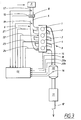
- FIG. 3 shows a schematic diagram illustrating an internal combustion engine.
- the engine includes at least one cylinder 1-4 containing a reciprocating piston within a combustion chamber, which piston is connected to an output crankshaft.
- the engine has an intake system including an intake conduit 5 and an intake manifold 6 connecting the combustion chamber to a source of ambient air.
- the intake system includes an injector for supplying controlled amounts of fuel from a suitable fuel supply system to each cylinder.
- the intake system is arranged to receive air from an air cleaner 7 and supply the air to the intake manifold 6, where the air and fuel is mixed and supplied to the combustion chamber in the form of a combustible air-fuel mixture.
- the intake conduit 5 is further supplied with a throttle valve 8 that can be opened and closed for controlling the flow of air to the combustion chamber.
- the combustion chamber is provided with an intake valve and an exhaust valve (not shown) arranged to admit an air-fuel mixture and exhaust the combusted residual gases according to a conventional 4-stroke cycle.
- the engine is also provided with an exhaust system including an exhaust manifold 9 ducted to the combustion chamber. From the combustion chamber the exhaust gases are conventionally ducted to a conventional exhaust system including a catalytic converter 10, a muffler arrangement 11 and a tailpipe 12.
- the engine is controlled by a central processing unit (CPU) 13 that receives a number of input signals from various conventional sensors.
- the engine is provided with a speed sensor 14 for measuring the revolutions of the engine at the end of the crankshaft.
- the torque output can be determined either by using the output signal from said speed sensor, or by means of the airflow and the ignition timing. In the latter case the ignition timing is determined by the CPU 13 and the air mass flow can be determined by the throttle setting or a separate air mass sensor (not shown).
- the throttle 8 is provided with a sensor 15 that measures the degree of opening, or throttle angle, in order to determine the mass flow of air supplied to the engine.
- the converter 10 is provided with a temperature sensor 16 in order to determine when the light-off, or operating temperature is reached.
- Additional sensors may include a number of temperature sensors, used for measuring ambient (intake) air temperature 17, exhaust gas temperature 18, and an engine coolant temperature.
- Pressure sensors 19 are used to measure intake air pressure and, when appropriate, the boost pressure from a turbocharger.
- One or more sensors may be provided for specific emissions in the exhaust, such as a sensor 20a for nitrous oxides (NOx).
- the signals from the sensors are transmitted to the CPU 13, which monitors the signals and uses a predetermined mapping of engine parameters to determine the operating status of the engine. By comparing the current values of a number of characteristic parameters with corresponding desired values for a particular operating condition, the CPU 13 will transmit signals 21-24 to the respective fuel injectors and/or throttle 8 to correct the current values.
- the CPU can also control and adjust the ignition timing.
- the CPU 13 will transmit signals to the throttle 8 and the fuel injectors in accordance with a predetermined data mapping stored in the CPU 13.
- the initial settings transmitted to the throttle 8 and the fuel injectors are intended to supply the combustion chamber with a lean air-fuel mixture, preferably with an air factor ⁇ >1,05.
- the throttle 8 is initially set to be sufficiently open to ensure that the engine operates at a high load.
- a typical throttle angle for this purpose is 30°, although different angles are possible depending on the valve properties.
- the CPU 13 will regulate the composition of the air-fuel mixture. If no misfiring of the engine is detected and if the engine speed is within a predetermined range, the CPU 13 will transmit signals to the fuel injectors to adjust the amount of fuel up or down in order to reduce the difference between the target and the actual air/fuel ratio.
- the arrangement according to the invention also allows for adjustment of the amount of injected fuel for each consecutive cylinder during the start-up operation.
- the CPU 13 will adjust the air factor ⁇ to a predetermined value when the engine is started.
- the value of the actual air factor ⁇ A is determined by the lean start strategy used for each type of engine and is usually selected within the range of 1,02 > ⁇ A > 1,5. In this particular case, the selected value of ⁇ A is 1,05 as indicated in Figure 4.
- the fuel/air ratio is the amount of fuel in comparison with the amount of air. This is the reciprocal of the air/fuel ratio that is described by the air factor ⁇ .
- the fuel factor is the supplied amount of fuel over the theoretically required amount of fuel. As the CPU 13 is arranged to control the amount of injected fuel, it usually operates with the fuel factor instead of the air factor.
- the engine idling speed is allowed to vary as a function of the difference between the target and the actual air/fuel ratio.
- the CPU 13 will not take any action to correct variations in the idling speed as long as it remains within a predetermined range.
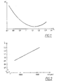
- Figure 4 shows the target air factor ⁇ T and the relative torque plotted with respect to different idling speeds for an internal combustion engine.
- the values of the target air factor ⁇ T is programmed as a map containing the corresponding fuel factors in the CPU 13.
- the actual, or target combustion air factor ⁇ A is set to be substantially constant at ⁇ A ⁇ 1,05.
- ⁇ A ⁇ T .
- the example shows how the operating line is adjusted to an idling speed N 2 of just under 1150 rpm with a corresponding target air factor of ⁇ T ⁇ 0,85.
- the enrichment of the target air factor to ⁇ T ⁇ 0,85 will cause an enleanment of 20% of the actual air factor (to ⁇ A ⁇ 1,1).
- the reason for this is that the CPU 13 detects a reduction in engine speed and enriches the air/fuel ratio to compensate.
- the reduction in engine speed causes a temporarily increased pressure in the intake conduit, while a part of the extra fuel injected settles on the wall of the intake conduit.
- the engine is started from cold, as much as 20% of the injected fuel may collect or condense on the wall of an intake pipe in the manifold 6.
- the latter effect is one reason why the enriched target air factor ⁇ T will still give a lean actual air factor ⁇ A for the air-fuel mixture in the combustion chamber.
- the engine will be allowed to run at a slightly lower idling speed, but with substantially the same air/fuel ratio, when a low volatile fuel is used.
- the initial air/fuel ratio settings and the subsequent calibration is performed using a mapping stored in the CPU 13.
- the CPU 13 will automatically set the desired air/fuel ratio after start-up and compensate the idling speed when changes in fuel volatility as well as perform corrections when variations in the idling speed occur.
- the above example relates to a case when a fuel property such as volatility decreases, but the method will of course also correct the settings of the engine if said fuel property returns to normal or improves above normal value. In the latter case a target air factor of ⁇ T > 1,1 may cause drivability problems due to the reduced available torque.
- the CPU map must be programmed to handle such cases.
- the above lean start strategy is interrupted either when the catalytic converter 10 reaches its operating temperature or when the throttle 8 is operated by the driver. In the latter case, the strategy can be set to resume if the engine speed returns to idling speed before the catalytic converter 10 is operational.
- the lean start strategy is also interrupted if problems with engine stability are detected. For reasons of drivability, some operating conditions may require a rich air-fuel mixture or adjustment of the throttle 8 and/or the ignition timing.
Claims (14)
- Procédé pour commander un moteur à combustion interne pendant une opération de démarrage à froid, caractérisé en ce que le moteur est alimenté à l'aide d'un mélange air-carburant ayant un rapport air/carburant pauvre sensiblement constant lorsque le moteur est démarré, et en ce que le moteur a une vitesse de ralenti qui varie en fonction de la différence entre un rapport air/carburant cible et le rapport air/carburant réel, où le rapport air/carburant cible est le rapport air/carburant pauvre dans le mélange air-carburant alimenté dans le conduit d'admission du moteur et le rapport air/carburant réel est le rapport air/carburant dans le mélange air-carburant dans une chambre de combustion associée au conduit d'admission.
- Procédé selon la revendication 1, caractérisé en ce que le rapport air/carburant cible de l'air d'admission est variable et est utilisé pour commander la vitesse de ralenti du moteur.
- Procédé selon la revendication 2, caractérisé en ce qu'un calibrage du rapport air/carburant cible est effectué pour donner une vitesse de ralenti nominale (N1) pendant un démarrage à froid, où ledit rapport air/carburant est enrichi lorsqu'une réduction de la vitesse de ralenti est détectée, et le rapport est rendu plus pauvre lorsqu'une augmentation de la vitesse de ralenti est détectée.
- Procédé selon la revendication 3, caractérisé en ce que la vitesse de ralenti nominale (N1) pendant un démarrage à froid est plus élevée qu'une vitesse de ralenti nominale prédéterminée pendant un fonctionnement normal du moteur.
- Procédé selon la revendication 3, caractérisé en ce que lorsque le calibrage est effectué, la vitesse de ralenti nominale varie en fonction de la volatilité du carburant tout en maintenant ledit rapport air/carburant réel sensiblement constant.
- Procédé selon la revendication 5, caractérisé en ce que lorsque le calibrage est effectué, la vitesse de ralenti nominale est réduite si on utilise un carburant ayant une volatilité inférieure.
- Procédé selon la revendication 3, caractérisé en ce qu'un papillon des gaz (8) situé dans un conduit d'admission d'air (5) est maintenu à un angle d'ouverture sensiblement fixe pendant le calibrage.
- Procédé selon la revendication 1, caractérisé en ce que le moteur fonctionne en régime pauvre avec un facteur d'air réel (λA) situé dans une plage de 1,02 < λA < 1,2 pendant un ralenti de démarrage à froid.
- Moteur à combustion interne, lequel moteur est muni d'un conduit d'admission d'air et d'un papillon des gaz (8) agencés pour alimenter de l'air d'admission vers au moins une chambre de combustion (1-4), au moins un injecteur de carburant pour alimenter du carburant vers l'air d'admission, une sortie (12) pour mettre à l'échappement des gaz en aval du moteur, et une unité centrale de traitement (13) pour commander le fonctionnement dudit moteur, caractérisé en ce que le moteur est agencé pour agir avec un rapport air/carburant réel pauvre pendant un démarrage à froid du moteur, et en ce que le moteur a une vitesse de ralenti qui est agencée pour varier en fonction de la différence entre un rapport air/carburant cible et le rapport air/carburant réel, où le rapport air/carburant cible est le rapport air/carburant dans le mélange air-carburant dans le conduit d'admission du moteur et le rapport air/carburant réel est le rapport air/carburant dans le mélange air-carburant dans une chambre de combustion associée au conduit d'admission.
- Moteur à combustion interne selon la revendication 9, caractérisé en ce que les injecteurs de carburant sont agencés pour faire varier le rapport air/carburant cible de l'air d'admission afin de commander la vitesse de ralenti du moteur.
- Moteur à combustion interne selon la revendication 10, caractérisé en ce que le rapport air/carburant cible est agencé pour être calibré par une unité centrale de traitement (13), afin d'aboutir à une vitesse de ralenti nominale (N1), où ledit rapport air/carburant est enrichi lorsqu'une réduction de la vitesse de ralenti est détectée, et le rapport est rendu plus pauvre lorsqu'une augmentation de la vitesse de ralenti est détectée.
- Moteur à combustion interne selon la revendication 11, caractérisé en ce qu'un papillon des gaz (8) situé dans le conduit d'air d'admission (5) est maintenu à un angle d'ouverture sensiblement fixe pendant le calibrage.
- Moteur à combustion interne selon la revendication 11, caractérisé en ce que l'unité centrale de traitement (13) est munie d'un mappage du rapport air/carburant cible (par rapport à une vitesse moteur) et est agencée pour maintenir ledit rapport air/carburant réel sensiblement constant si la vitesse de ralenti nominale varie du fait de changements de volatilité du carburant.
- Moteur à combustion interne selon la revendication 9, caractérisé en ce que moteur est agencé pour fonctionner avec un facteur d'air réel (λA) situé dans une plage de 1,02 < λA < 1,2 pendant un ralenti de démarrage à froid.
Priority Applications (3)
| Application Number | Priority Date | Filing Date | Title |
|---|---|---|---|
| EP02445067A EP1367247B1 (fr) | 2002-05-28 | 2002-05-28 | Méthode de contrôle d'un moteur à combustion interne |
| DE60209209T DE60209209T2 (de) | 2002-05-28 | 2002-05-28 | Verfahren zum Kontrollieren einer Brennkraftmaschine |
| US10/445,613 US6941927B2 (en) | 2002-05-28 | 2003-05-28 | Internal combustion engine control during cold start |
Applications Claiming Priority (1)
| Application Number | Priority Date | Filing Date | Title |
|---|---|---|---|
| EP02445067A EP1367247B1 (fr) | 2002-05-28 | 2002-05-28 | Méthode de contrôle d'un moteur à combustion interne |
Publications (2)
| Publication Number | Publication Date |
|---|---|
| EP1367247A1 EP1367247A1 (fr) | 2003-12-03 |
| EP1367247B1 true EP1367247B1 (fr) | 2006-02-15 |
Family
ID=29414881
Family Applications (1)
| Application Number | Title | Priority Date | Filing Date |
|---|---|---|---|
| EP02445067A Expired - Lifetime EP1367247B1 (fr) | 2002-05-28 | 2002-05-28 | Méthode de contrôle d'un moteur à combustion interne |
Country Status (3)
| Country | Link |
|---|---|
| US (1) | US6941927B2 (fr) |
| EP (1) | EP1367247B1 (fr) |
| DE (1) | DE60209209T2 (fr) |
Families Citing this family (16)
| Publication number | Priority date | Publication date | Assignee | Title |
|---|---|---|---|---|
| MXPA06001295A (es) * | 2003-08-06 | 2006-04-11 | Procter & Gamble | Articulo absorbente que comprende material recubierto hinchable en agua. |
| EP1651282A1 (fr) | 2003-08-06 | 2006-05-03 | The Procter & Gamble Company | Structures absorbantes comprenant un materiau revetu gonflable dans l'eau |
| WO2005014697A1 (fr) * | 2003-08-06 | 2005-02-17 | The Procter & Gamble Company | Matiere gonflable dans l'eau revetue |
| EP1518567B1 (fr) * | 2003-09-25 | 2017-06-28 | The Procter & Gamble Company | Articles absorbants comprenant des zones d'acquisition et des particules revêtues et superabsorbantes |
| WO2006082239A2 (fr) * | 2005-02-04 | 2006-08-10 | Basf Aktiengesellschaft | Materiau absorbant l'eau avec revetement de polymeres formant un film elastique |
| WO2006083583A2 (fr) * | 2005-02-04 | 2006-08-10 | The Procter & Gamble Company | Structure absorbante comprenant une matiere amelioree absorbant l'eau |
| TW200635959A (en) * | 2005-02-04 | 2006-10-16 | Basf Ag | Water swellable material |
| US20080154224A1 (en) * | 2005-02-04 | 2008-06-26 | Basf Aktiengesellschaft | Process for Producing a Water-Absorbing Material Having a Coating of Elastic Filmforming Polymers |
| JP2008529590A (ja) | 2005-02-04 | 2008-08-07 | ザ プロクター アンド ギャンブル カンパニー | 改善された吸水性材料を有する吸収性構造体 |
| DE602006015422D1 (de) * | 2005-02-04 | 2010-08-26 | Basf Se | Verfahren zur herstellung eines wasserabsorbierenden materials mit einem überzug aus elastischen filmbildenden polymeren |
| US7242826B2 (en) * | 2005-06-15 | 2007-07-10 | Imalux Corporation | Optical fiber lateral scanner for a miniature optical fiber probe |
| US20080017168A1 (en) * | 2006-07-20 | 2008-01-24 | Degroot Kenneth P | Engine Event-Based Correction Of Engine Speed Fluctuations |
| US7658178B2 (en) * | 2007-06-07 | 2010-02-09 | Chrysler Group Llc | Engine event-based correction of engine speed fluctuations |
| WO2012002859A1 (fr) * | 2010-07-01 | 2012-01-05 | Husqvarna Ab | Procédé de distribution de carburant de démarrage à un moteur à combustion interne |
| GB2498553B (en) * | 2012-01-20 | 2015-07-01 | Jaguar Land Rover Ltd | Improvements in controlling internal combustion engine emissions |
| CN113898488B (zh) * | 2021-10-22 | 2023-09-05 | 中车大连机车车辆有限公司 | 一种米勒循环柴油机低温环境起动控制方法 |
Family Cites Families (9)
| Publication number | Priority date | Publication date | Assignee | Title |
|---|---|---|---|---|
| US43247A (en) * | 1864-06-21 | Improved bayonet-blank | ||
| JP2737426B2 (ja) * | 1991-03-08 | 1998-04-08 | 日産自動車株式会社 | 内燃機関の燃料噴射制御装置 |
| US5579737A (en) * | 1993-07-21 | 1996-12-03 | Unisia Jecs Corporation | Method and apparatus for electronically controlling a fuel supply to an internal combustion engine |
| US5715796A (en) | 1995-02-24 | 1998-02-10 | Honda Giken Kogyo Kabushiki Kaisha | Air-fuel ratio control system having function of after-start lean-burn control for internal combustion engines |
| JP3620228B2 (ja) * | 1997-07-31 | 2005-02-16 | トヨタ自動車株式会社 | 内燃機関の制御装置 |
| DE19740699C2 (de) * | 1997-09-16 | 1999-08-26 | Siemens Ag | Verfahren zum Aufheizen eines Katalysators beim Start einer Brennkraftmaschine |
| US6098605A (en) | 1999-01-21 | 2000-08-08 | Tjb Engineering, Inc. | Method and apparatus for operation of an internal combustion engine in a true closed loop fuel control |
| US6637413B2 (en) * | 2000-09-14 | 2003-10-28 | Delphi Technologies, Inc. | Engine starting and warm-up fuel control method having low volatility fuel detection and compensation |
| JP2002130014A (ja) * | 2000-10-18 | 2002-05-09 | Denso Corp | 内燃機関の燃料供給量制御装置 |
-
2002
- 2002-05-28 DE DE60209209T patent/DE60209209T2/de not_active Expired - Lifetime
- 2002-05-28 EP EP02445067A patent/EP1367247B1/fr not_active Expired - Lifetime
-
2003
- 2003-05-28 US US10/445,613 patent/US6941927B2/en not_active Expired - Lifetime
Also Published As
| Publication number | Publication date |
|---|---|
| US6941927B2 (en) | 2005-09-13 |
| EP1367247A1 (fr) | 2003-12-03 |
| DE60209209D1 (de) | 2006-04-20 |
| DE60209209T2 (de) | 2006-11-16 |
| US20040025836A1 (en) | 2004-02-12 |
Similar Documents
| Publication | Publication Date | Title |
|---|---|---|
| US4967714A (en) | Apparatus for controlling engine operable on gasoline/alcohol fuel blend | |
| JP3403728B2 (ja) | 空燃比制御方法 | |
| EP1367247B1 (fr) | Méthode de contrôle d'un moteur à combustion interne | |
| EP0239095B1 (fr) | Méthode et système de commande de moteurs à combustion interne | |
| US4982709A (en) | Apparatus for controlling the idling speed of engine operable on gasoline/alcohol fuel blend | |
| US5278762A (en) | Engine control apparatus using exhaust gas temperature to control fuel mixture and spark timing | |
| US8958971B2 (en) | System and method to control an electronically-controlled turbocharger | |
| US6308671B1 (en) | Method of increasing torque and/or reducing emissions by varying the timing of intake and/or exhaust valves | |
| US7150264B2 (en) | Control device for internal combustion engine | |
| US5499607A (en) | Fuel characteristic detecting system for internal combustion engine | |
| US5150694A (en) | Diesel engine closed loop air/fuel ratio control | |
| US4913099A (en) | Fuel injection control apparatus | |
| GB2049229A (en) | System and method for controlling egr in internal combustion engine | |
| US6513509B1 (en) | Device for controlling the air-fuel ratio of an internal combustion engine | |
| JPH0458051A (ja) | 内燃機関の使用燃料判別装置 | |
| EP0216111B1 (fr) | Système d'injection de carburant et méthode de commande de celui-ci | |
| US7198030B2 (en) | Internal combustion engine | |
| US7401605B2 (en) | Fuel injection control system for engine | |
| US6805091B2 (en) | Method for determining the fuel content of the regeneration gas in an internal combustion engine comprising direct fuel-injection with shift operation | |
| EP1108131A1 (fr) | Procede de reduction des emissions d'un moteur a combustion interne lors du demarrage a froid | |
| US8161941B2 (en) | Control device for internal combustion engine | |
| US20030010324A1 (en) | Method, computer programme and control and/or regulation device for operating an internal combustion engine | |
| US6098605A (en) | Method and apparatus for operation of an internal combustion engine in a true closed loop fuel control | |
| WO2000043659A9 (fr) | Procede et appareil permettant le fonctionnement d'un moteur a combustion interne en commande de carburant en vraie boucle fermee | |
| EP1394393B1 (fr) | Procédé de commande d'un moteur à combustion interne |
Legal Events
| Date | Code | Title | Description |
|---|---|---|---|
| PUAI | Public reference made under article 153(3) epc to a published international application that has entered the european phase |
Free format text: ORIGINAL CODE: 0009012 |
|
| AK | Designated contracting states |
Kind code of ref document: A1 Designated state(s): AT BE CH CY DE DK ES FI FR GB GR IE IT LI LU MC NL PT SE TR |
|
| AX | Request for extension of the european patent |
Extension state: AL LT LV MK RO SI |
|
| RIN1 | Information on inventor provided before grant (corrected) |
Inventor name: HAKANSSON, HENRIK Inventor name: BURGDORF, KLAAS Inventor name: ALMKVIST, GOERAN Inventor name: FREDRIKSSON, LARS MIKAEL |
|
| 17P | Request for examination filed |
Effective date: 20040527 |
|
| AKX | Designation fees paid |
Designated state(s): DE GB SE |
|
| 17Q | First examination report despatched |
Effective date: 20040728 |
|
| GRAP | Despatch of communication of intention to grant a patent |
Free format text: ORIGINAL CODE: EPIDOSNIGR1 |
|
| GRAS | Grant fee paid |
Free format text: ORIGINAL CODE: EPIDOSNIGR3 |
|
| GRAA | (expected) grant |
Free format text: ORIGINAL CODE: 0009210 |
|
| AK | Designated contracting states |
Kind code of ref document: B1 Designated state(s): DE GB SE |
|
| REG | Reference to a national code |
Ref country code: GB Ref legal event code: FG4D |
|
| REF | Corresponds to: |
Ref document number: 60209209 Country of ref document: DE Date of ref document: 20060420 Kind code of ref document: P |
|
| REG | Reference to a national code |
Ref country code: SE Ref legal event code: TRGR |
|
| PLBE | No opposition filed within time limit |
Free format text: ORIGINAL CODE: 0009261 |
|
| STAA | Information on the status of an ep patent application or granted ep patent |
Free format text: STATUS: NO OPPOSITION FILED WITHIN TIME LIMIT |
|
| 26N | No opposition filed |
Effective date: 20061116 |
|
| REG | Reference to a national code |
Ref country code: DE Ref legal event code: R082 Ref document number: 60209209 Country of ref document: DE Representative=s name: ISARPATENT, DE |
|
| REG | Reference to a national code |
Ref country code: DE Ref legal event code: R081 Ref document number: 60209209 Country of ref document: DE Owner name: VOLVO CAR CORPORATION, SE Free format text: FORMER OWNER: FORD GLOBAL TECHNOLOGIES, INC., DEARBORN, US Effective date: 20120208 Ref country code: DE Ref legal event code: R082 Ref document number: 60209209 Country of ref document: DE Representative=s name: ISARPATENT GBR PATENT- UND RECHTSANWAELTE, DE Effective date: 20120208 Ref country code: DE Ref legal event code: R082 Ref document number: 60209209 Country of ref document: DE Representative=s name: ISARPATENT PATENTANWAELTE BEHNISCH, BARTH, CHA, DE Effective date: 20120208 Ref country code: DE Ref legal event code: R081 Ref document number: 60209209 Country of ref document: DE Owner name: VOLVO CAR CORPORATION, SE Free format text: FORMER OWNER: FORD GLOBAL TECHNOLOGIES, INC., DEARBORN, MICH., US Effective date: 20120208 Ref country code: DE Ref legal event code: R082 Ref document number: 60209209 Country of ref document: DE Representative=s name: ISARPATENT - PATENTANWAELTE- UND RECHTSANWAELT, DE Effective date: 20120208 |
|
| REG | Reference to a national code |
Ref country code: GB Ref legal event code: 732E Free format text: REGISTERED BETWEEN 20120510 AND 20120516 |
|
| REG | Reference to a national code |
Ref country code: GB Ref legal event code: 732E Free format text: REGISTERED BETWEEN 20120517 AND 20120523 |
|
| PGFP | Annual fee paid to national office [announced via postgrant information from national office to epo] |
Ref country code: SE Payment date: 20150519 Year of fee payment: 14 Ref country code: GB Payment date: 20150511 Year of fee payment: 14 |
|
| GBPC | Gb: european patent ceased through non-payment of renewal fee |
Effective date: 20160528 |
|
| PG25 | Lapsed in a contracting state [announced via postgrant information from national office to epo] |
Ref country code: SE Free format text: LAPSE BECAUSE OF NON-PAYMENT OF DUE FEES Effective date: 20160529 |
|
| PG25 | Lapsed in a contracting state [announced via postgrant information from national office to epo] |
Ref country code: GB Free format text: LAPSE BECAUSE OF NON-PAYMENT OF DUE FEES Effective date: 20160528 |
|
| PGFP | Annual fee paid to national office [announced via postgrant information from national office to epo] |
Ref country code: DE Payment date: 20210421 Year of fee payment: 20 |
|
| REG | Reference to a national code |
Ref country code: DE Ref legal event code: R071 Ref document number: 60209209 Country of ref document: DE |