EP1366212B1 - Bipolar assembly for filter-press electrolyser - Google Patents
Bipolar assembly for filter-press electrolyser Download PDFInfo
- Publication number
- EP1366212B1 EP1366212B1 EP02729944A EP02729944A EP1366212B1 EP 1366212 B1 EP1366212 B1 EP 1366212B1 EP 02729944 A EP02729944 A EP 02729944A EP 02729944 A EP02729944 A EP 02729944A EP 1366212 B1 EP1366212 B1 EP 1366212B1
- Authority
- EP
- European Patent Office
- Prior art keywords
- single sheet
- assembly
- flange
- perimetral
- flanges
- Prior art date
- Legal status (The legal status is an assumption and is not a legal conclusion. Google has not performed a legal analysis and makes no representation as to the accuracy of the status listed.)
- Expired - Lifetime
Links
Images

Classifications
-
- C—CHEMISTRY; METALLURGY
- C25—ELECTROLYTIC OR ELECTROPHORETIC PROCESSES; APPARATUS THEREFOR
- C25B—ELECTROLYTIC OR ELECTROPHORETIC PROCESSES FOR THE PRODUCTION OF COMPOUNDS OR NON-METALS; APPARATUS THEREFOR
- C25B9/00—Cells or assemblies of cells; Constructional parts of cells; Assemblies of constructional parts, e.g. electrode-diaphragm assemblies; Process-related cell features
- C25B9/70—Assemblies comprising two or more cells
- C25B9/73—Assemblies comprising two or more cells of the filter-press type
- C25B9/75—Assemblies comprising two or more cells of the filter-press type having bipolar electrodes
-
- C—CHEMISTRY; METALLURGY
- C25—ELECTROLYTIC OR ELECTROPHORETIC PROCESSES; APPARATUS THEREFOR
- C25B—ELECTROLYTIC OR ELECTROPHORETIC PROCESSES FOR THE PRODUCTION OF COMPOUNDS OR NON-METALS; APPARATUS THEREFOR
- C25B11/00—Electrodes; Manufacture thereof not otherwise provided for
- C25B11/02—Electrodes; Manufacture thereof not otherwise provided for characterised by shape or form
- C25B11/036—Bipolar electrodes
-
- Y—GENERAL TAGGING OF NEW TECHNOLOGICAL DEVELOPMENTS; GENERAL TAGGING OF CROSS-SECTIONAL TECHNOLOGIES SPANNING OVER SEVERAL SECTIONS OF THE IPC; TECHNICAL SUBJECTS COVERED BY FORMER USPC CROSS-REFERENCE ART COLLECTIONS [XRACs] AND DIGESTS
- Y02—TECHNOLOGIES OR APPLICATIONS FOR MITIGATION OR ADAPTATION AGAINST CLIMATE CHANGE
- Y02E—REDUCTION OF GREENHOUSE GAS [GHG] EMISSIONS, RELATED TO ENERGY GENERATION, TRANSMISSION OR DISTRIBUTION
- Y02E60/00—Enabling technologies; Technologies with a potential or indirect contribution to GHG emissions mitigation
- Y02E60/30—Hydrogen technology
- Y02E60/36—Hydrogen production from non-carbon containing sources, e.g. by water electrolysis
Definitions
- the present invention relates to a new bipolar assembly for filter press electrolyser.
- Hydrochloric acid in the following description, is an important by-product generated in a large amount by a number of industrial processes, among which particularly important are the synthesis of vinyl chloride by dichloroethane pyrolisis, followed by polymerisation to polyvinylchloride (PVC), and of several isocyanates which reacted with glycoles permit to obtain the family of polyurethanes, increasingly employed for the production of paints and of expanded cell materials prized for thermal insulation systems, such as insulation for refrigerators and walls of buildings.
- PVC polyvinylchloride
- Such electrolysis can be carried out according to two technologies respectively based on the utilisation of gaseous hydrochloric acid (this being the physical state in which HCl is formed by dichloroethane pyrolisis and isocyanate synthesis) or of an aqueous solution of HCl obtained by sending the gaseous HCl to a water-fed absorption column.
- gaseous hydrochloric acid this being the physical state in which HCl is formed by dichloroethane pyrolisis and isocyanate synthesis
- aqueous solution of HCl obtained by sending the gaseous HCl to a water-fed absorption column.
- Such column is an equipment normally present in the plants that generate HCl as a by-product, since the aqueous solution practically represents the only way through which commercialisation can be effected.
- the two walls of the cathodic and anodic compartment of two adjacent cells can be put in mechanical and electrical contact either by means of a suitable compression (a concept known to the experts of the field as "single cell") or through a connection by suitable clamping elements, such as nuts and bolts or welds (bipolar assemblies).
- a suitable compression a concept known to the experts of the field as "single cell”
- suitable clamping elements such as nuts and bolts or welds (bipolar assemblies).
- the cathodic and the anodic compartment are made with the same metal facilitates substantially the manufacturing procedures and more interestingly makes possible a new type of design in which a cathode and an adjacent anode are separated by a single wall whose two faces cover the function of the two separated and adjacent walls of the traditional technology.
- This type of construction minimises the employment of expensive material such as titanium and alloys thereof with an undeniably relevant economic advantage, and is outlined in very general terms in US 5,770,035.
- the wall must be subjected, operating with the known procedures, to a double forming since both flanges, cathodic and anodic, are necessarily parts of the same wall.
- the double forming independently of the fact that it be carried out by press-shaping or by folding, introduces high mechanical stresses in the material with frequent unacceptabte planarity and/or defects such as fractures.
- the present invention describes a design of bipolar assemblies comprising a single separating sheet with the dual function of anodic wall and cathodic wall made of corrosion resistant metal or metal alloy, and provided with an anodic perimetral flange and a cathodic perimetral flange; at least one of said perimetral flanges is made by a pre-formed element, and is not made out of press-shaping or folding the separating wall.
- the cathodic and the anodic perimetral flange are obtained by combining the folding of the peripheral portion of the sheet with a frame made out of a rod or a tube, both having a quadrangular section, made of a material of equivalent type as that of said sheet.
- one of the flanges is obtained by folding the peripheral portion of the sheet, and the other is a pre-formed flange welded to the sheet itself: a reinforcing element is preferably interposed between the two flanges.
- the anodic perimetral flange and the cathodic one constitute a generally U-shaped pre-formed integral element, welded to said separating sheet; preferably, a reinforcing element is interposed between the anodic and the cathodic peripheral flange.
- the pre-formed integral element is obtained by folding of a second sheet, or by welding of two pre-formed flanges.
- the invention is directed to a method of catalytic activation of a bipolar assembly comprising at least one electrode, and preferably a couple of electrodes, fixed to the two anodic and cathodic faces of the sheet.
- said bipolar assembly subjected to catalytic activation is a newly manufactured assembly.
- said bipolar assembly is a previously catalysed assembly already operated in an electrolyser, whose catalytic activation, exhausted, is restored by reactivation.
- the invention is directed to an electrolyser comprising a multiplicity of bipolar assemblies according to one of the above described embodiments.
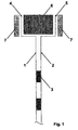
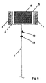
- Fig. 1 and fig. 2 show two cross-sections of a bipolar assembly corresponding to the design according to the prior art in case the anodic and cathodic walls are two distinct sheets and a single sheet respectively.
- the essential constructive elements of the assembly are indicated, wherein 1 and 2 are the separate anodic and cathodic wall, 3 the welds providing to ensure the mechanical stability and the electrical continuity needed to allow the passage of the electric current, 4 the surface of the anodic flange, 5 the surface of the cathodic flange, 6 a perimetral reinforcing element made of a metal or plastic material rod suitable to guarantee that the flanges may be compressed without deformations or deflections taking place, 7 the gaskets, respectively anodic (at the left) and cathodic (at the right), which seal the perimetral surface of both flanges under compression hindering the leakage of the fluids contained in the anodic and in the cathodic compartments.
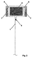
- an embodiment according to the prior art is outlined in case the two walls of the adjacent anodic and cathodic compartments are constituted by a single sheet. Based on this kind of construction the peripheral portion of the single, sheet is subjected to a sequence of folds, at least five or preferably six as shown in the figure, around the perimetral reinforcing element to form the two flange surfaces, anodic and cathodic.
- 1 is the single sheet covering at the same time the roles of walls 1 and 2 in fig. 1,4 is the anodic flange surface, 5 is the cathodic flange surface, 6 is the perimetral reinforcing element with the same functions of the one of fig.
- 1, 7 are the anodic and cathodic gaskets
- 8 is the weld for fixing the free edge of the folded portion of sheet having the aim of preventing the penetration of the fluid from the cathodic compartment (at the right hand side in the figure).
- This fluid might be corrosive and the contact thereof with the perimetral reinforcing element 6 would force it to be built of a corrosion resistant material and thus intrinsically expensive. If the element 6 is safely protected from the contact with aggressive fluids, the construction material may be cheap carbon steel.
- the assembly of fig. 2 is certainly advantageous with respect to the more common type of construction according to the prior art of fig. 1 as it makes use of a single sheet of expensive material, e.g. titanium and alloys thereof for the case of hydrochloric acid solution electrolysis, allowing to eliminate the welds 3 of fig.1 of mechanical assembly and electrical continuity.
- the assembly is however penalised by the multiple folding needed to form the two anodic and cathodic flange surfaces making use of the same peripheral portion of sheet: this kind of folding is very complex to perform and induces high mechanical stresses with high risk of defect formation and consequent unacceptable percentage of piece rejection in phase of production quality control.
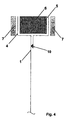
- Fig. 3 shows a first embodiment according to the invention of the assembly wherein the walls of the two adjacent anodic and cathodic compartments consist of a single sheet 1 and the peripheral portion of said single sheet 1 is folded so as to form the surface 4 only of the anodic flange (as preferred in the case of hydrochloric acid solution electrolysis, without however excluding the alternative wherein the only flange surface that is formed is the cathodic surface), and said single surface is welded at 9 to a frame 14 constructed with corrosion resistant material.
- frame 14 is made of a rod, or preferably of a tube with polygonal section, preferably quadrangular, to decrease the amount of material resistant to corrosion, and thus expensive, and moreover the weld 9 can optionally be a double weld as shown in the figure to ensure a higher reliability towards the possible leakage of the fluid contained in the cathodic compartment to the external environment.
- This first constructive alternative according to the invention allows to maintain the mechanical folding stresses within very low levels, certainly not able to generate defects in the material of the sheet.
- the quality of the weld or welds 9 and suitable speeds and production costs are guaranteed by adequate clamping equipment for the various pieces and by the modem automated welding techniques, in particular the laser technique. Examining fig.
- the folded sheet - frame assembly creates a crevice 15 in which the process liquid could infiltrate and stagnate: this situation does not cause in general any particular inconvenience, with the 'exception of the specific case in which such liquid contains chlorides and in particular it is acidic and at a temperature higher than ambient, as effectively happens in the case of hydrochloric acid solution electrolysis, In this situation a corrosive attack confined within the crevice zone may in fact develop.
- the protection against this type of attack is effected either selecting a material characterised by higher resistance, for instance in the mentioned case of hydrochloric acid solution electrolysis the use of titanium - 0.2% palladium alloy instead of titanium, or applying a thin protective film to the crevice zone.
- These films well known in the electrochemical technology, generally contain small amounts of noble metals, such as platinum, ruthenium or iridium, or oxides thereof.
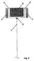
- Fig. 4 shows a variation of the embodiment of fig. 3 having the purpose of avoiding the use of the frame 14 made of a rod or tube with quadrangular section made with corrosion resistant material.
- the assembly always as a cross-section, comprises again the single sheet 1 with the peripheral portion folded to form only the anodic flange 4 as already seen in fig. 3, with the difference that the frame 14 of corrosion resistant material is replaced by a further pre-formed flange 5 which acts as cathodic flange and is welded to the sheet 1 through weld 10, performed with an automated procedure, preferably with the laser technology.
- the weld 10 can be realised as a double weld (not shown in the figure).
- the perimetral reinforcing element does not come in contact with any corrosive fluid and is therefore manufactured with a low cost material, e.g. carbon steel.
- the embodiment of fig. 4 allows a saving of expensive material, being on the other hand more delicate as regards the final planarity of the piece, important to facilitate the assemblage of the electrolysers.
- FIG. 5 A further constructive alternative of the assembly of fig. 4 is given in fig. 5 where the single sheet 1 is not folded in its peripheral portion and the two surfaces of the anodic 4 and cathodic 5 flanges are obtained by means of a pre-formed perimetral element with U-shaped section that is welded to the single sheet with the weld 11.
- the construction material of the reinforcing element 6 is not critical: carbon steel is totally suitable.
- the solution illustrated in fig. 5 is characterised by the same reduced amount of expensive material and in addition it permits to obtain mor easily a good final planarity.
- the execution of weld 11 is relatively critical in order to obtain a high quality weld in fact it is necessary that the edge of the sheet be straight and free from imperfections, such as cutting barbs, and that the edge of the sheet and the pre-formed piece with U-shaped section be perfectly adhered reciprocally during the execution of the welding, which must be of the automated type, such as the laser technology.
- fig. 6 outlines an embodiment of the invention as a cross-section wherein the perimetral piece with U-shaped section discussed in the context of fig. 5 is premanufactured by welding two shells obtained from two metal strips with only two foldings: the assembling weld 12 of the two shells can be single or it can be double in case one wants to ensure a high reliability against infiltrations.
- the so premanufactured element is worked for instance in a press to obtain a high planarity.
- the piece presents a free edge protruding respect to the weld 12: this edge, whose requirements are to be straight and free of defects such as cutting barbs, is welded head-to-head (weld 13) to the edge of the sheet 1.
- This type of embodiment is less advantageous compared to the one described in fig. 5 essentially for the additional steps represented by the execution of the weld 12 and the pressing to restore the piece planarity required after the deformations induced by the welding procedure: on the other hand the press working ensures an adequate planarity also after effecting the weld 13.
- This last weld which is inevitably single as weld 11 of the assembly of fig. 5, is however easier to effect (the two edges to be joined are in a head-to-head position, while in the assembly of fig. 5 the surface of the perimetral piece with U-shaped section and the edge of the sheet are positioned at 90°).
- This ease of execution guarantees a high probability of absence of defects, which on the other hand as above said are at least in part tolerable.
- the welding be of automated type, preferably with laser technology.
- the assemblies outlined in figs. 3, 4, 5 and 6 must be completed with the relative anodes and cathodes: these are normally constituted by punched or expanded sheets or meshes of corrosion resistant metal or metal alloy, preferably provided with a thin superficial film of electrocatalytic material.
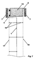
- Fig. 7 reproduces a cross-section of the assembly in fig. 3 wherein the anode 17 and the cathode 18 have been installed by fixing, e.g. welding, on adequate supports 16 in their turn connected to the wall 1 preferably by welding.
- fixing e.g. welding
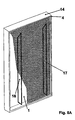
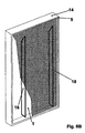
- the assembly of fig. 7 is reproduced in a three-dimensional representation in figs. 8A (view from the anode side) and 8B (view from the cathode side).
- the fixing by welding of the sheets or meshes previously provided with the electrocatalytic film results rather critical as in the welding zones the electrocatalytic film material is embedded in the molten zone with possible contamination and consequent generation of defects such as porosity and/or brittleness.
- the assembly of fig. 3 is characterised by being made of parts having the same thermal expansion coefficient and thus the assembly may be exposed to high temperatures without risks of distortion.
- the important consequence of this characteristic is that the new assemblies may be equipped with sheets or meshes free of electrocatalytic films (with a substantial simplification of the welds to the supports 16): in a subsequent phase the whole assemblies are subjected to the procedure of application of the electrocatalytic films to the sheets or meshes with the relative high temperatures.
- exhausted assemblies are treated to eliminate the remnants of the old electrocatalytic films, e.g. by means of sandblasting or chemical washing, then subjected to the application of new films according to a procedure that matches exactly the one utilised for new assemblies.
- a further advantage of the application of the electrocatalytic films to the assemblies including the punched or expanded sheets or meshes is given by the absence of damages to the films necessarily induced by the fixing welds on the sheets or meshes previously provided with the film according to the prior art.
Landscapes
- Chemical & Material Sciences (AREA)
- Engineering & Computer Science (AREA)
- Chemical Kinetics & Catalysis (AREA)
- Electrochemistry (AREA)
- Materials Engineering (AREA)
- Metallurgy (AREA)
- Organic Chemistry (AREA)
- Electrolytic Production Of Non-Metals, Compounds, Apparatuses Therefor (AREA)
- Electrodes For Compound Or Non-Metal Manufacture (AREA)
- Filtration Of Liquid (AREA)
- Heterocyclic Carbon Compounds Containing A Hetero Ring Having Oxygen Or Sulfur (AREA)
Applications Claiming Priority (3)
| Application Number | Priority Date | Filing Date | Title |
|---|---|---|---|
| ITMI20010401 | 2001-02-28 | ||
| IT2001MI000401A ITMI20010401A1 (it) | 2001-02-28 | 2001-02-28 | Nuovo assieme bipolare per elettrolizzatore a filtro-pressa |
| PCT/EP2002/002204 WO2002068718A2 (en) | 2001-02-28 | 2002-02-28 | Bipolar assembly for filter-press electrolyser |
Publications (2)
| Publication Number | Publication Date |
|---|---|
| EP1366212A2 EP1366212A2 (en) | 2003-12-03 |
| EP1366212B1 true EP1366212B1 (en) | 2004-10-06 |
Family
ID=11447040
Family Applications (1)
| Application Number | Title | Priority Date | Filing Date |
|---|---|---|---|
| EP02729944A Expired - Lifetime EP1366212B1 (en) | 2001-02-28 | 2002-02-28 | Bipolar assembly for filter-press electrolyser |
Country Status (16)
| Country | Link |
|---|---|
| US (1) | US6998030B2 (enExample) |
| EP (1) | EP1366212B1 (enExample) |
| JP (1) | JP4088527B2 (enExample) |
| KR (1) | KR100845727B1 (enExample) |
| CN (1) | CN1257316C (enExample) |
| AT (1) | ATE278821T1 (enExample) |
| AU (1) | AU2002302375A1 (enExample) |
| BR (1) | BR0207728B1 (enExample) |
| CA (1) | CA2438028C (enExample) |
| DE (1) | DE60201510T2 (enExample) |
| ES (1) | ES2229144T3 (enExample) |
| IT (1) | ITMI20010401A1 (enExample) |
| MX (1) | MXPA03007711A (enExample) |
| PL (1) | PL205527B1 (enExample) |
| RU (1) | RU2280104C2 (enExample) |
| WO (1) | WO2002068718A2 (enExample) |
Families Citing this family (6)
| Publication number | Priority date | Publication date | Assignee | Title |
|---|---|---|---|---|
| ITMI20042248A1 (it) * | 2004-11-19 | 2005-02-19 | Uhdenora Technologies Srl | Piatto bipolare per elettrolizzatore comprendente una singola parete |
| JP4718902B2 (ja) * | 2005-05-31 | 2011-07-06 | 三井化学株式会社 | 電解槽およびそれを用いた三フッ化窒素の製造方法 |
| ITMI20111070A1 (it) * | 2011-06-14 | 2012-12-15 | Uhdenora Spa | Componente di sostituzione per flange di elettrolizzatori |
| WO2013191140A1 (ja) * | 2012-06-18 | 2013-12-27 | 旭化成株式会社 | 複極式アルカリ水電解ユニット、及び電解槽 |
| ITMI20130563A1 (it) * | 2013-04-10 | 2014-10-11 | Uhdenora Spa | Metodo di adeguamento di celle elettrolitiche aventi distanze interelettrodiche finite |
| KR102709123B1 (ko) | 2024-04-30 | 2024-09-26 | 주식회사 테크로스 | 접착 고정식 수전해 모듈 |
Family Cites Families (14)
| Publication number | Priority date | Publication date | Assignee | Title |
|---|---|---|---|---|
| US1464840A (en) * | 1920-09-13 | 1923-08-14 | Toronto Power Company Ltd | Electrolytic apparatus |
| US4111779A (en) * | 1974-10-09 | 1978-09-05 | Asahi Kasei Kogyo Kabushiki Kaisha | Bipolar system electrolytic cell |
| IT1163737B (it) * | 1979-11-29 | 1987-04-08 | Oronzio De Nora Impianti | Elettrolizzatore bipolare comprendente mezzi per generare la ricircolazione interna dell'elettrolita e procedimento di elettrolisi |
| US4339323A (en) * | 1980-09-18 | 1982-07-13 | Ppg Industries, Inc. | Bipolar electrolyzer element |
| JPS599185A (ja) * | 1982-07-06 | 1984-01-18 | Asahi Chem Ind Co Ltd | イオン交換膜法電解槽 |
| DE3420483A1 (de) * | 1984-06-01 | 1985-12-05 | Hoechst Ag, 6230 Frankfurt | Bipolarer elektrolyseapparat mit gasdiffusionskathode |
| US4877499A (en) * | 1984-11-05 | 1989-10-31 | The Dow Chemical Company | Membrane unit for electrolytic cell |
| US4894128A (en) * | 1986-05-05 | 1990-01-16 | The Dow Chemical Company | Membrane unit for electrolytic cell |
| IT1200403B (it) * | 1985-03-07 | 1989-01-18 | Oronzio De Nora Impianti | Celle elettrolitiche mono e bipolari e relative strutture elettrodiche |
| US4578885A (en) * | 1985-07-29 | 1986-04-01 | The Dow Chemical Company | Tentering frame for sheet-like members |
| GB8626010D0 (en) * | 1986-10-30 | 1986-12-03 | Ici Plc | Assembling filter press type structure |
| JP3282691B2 (ja) * | 1993-04-30 | 2002-05-20 | クロリンエンジニアズ株式会社 | 電解槽 |
| JP2893238B2 (ja) * | 1994-03-14 | 1999-05-17 | 工業技術院長 | 高分子電解質膜を用いる水電解槽 |
| IT1282367B1 (it) * | 1996-01-19 | 1998-03-20 | De Nora Spa | Migliorato metodo per l'elettrolisi di soluzioni acquose di acido cloridrico |
-
2001
- 2001-02-28 IT IT2001MI000401A patent/ITMI20010401A1/it unknown
-
2002
- 2002-02-28 DE DE60201510T patent/DE60201510T2/de not_active Expired - Lifetime
- 2002-02-28 BR BRPI0207728-0A patent/BR0207728B1/pt not_active IP Right Cessation
- 2002-02-28 EP EP02729944A patent/EP1366212B1/en not_active Expired - Lifetime
- 2002-02-28 KR KR1020037011342A patent/KR100845727B1/ko not_active Expired - Fee Related
- 2002-02-28 PL PL363678A patent/PL205527B1/pl unknown
- 2002-02-28 RU RU2003128979/15A patent/RU2280104C2/ru active
- 2002-02-28 US US10/466,782 patent/US6998030B2/en not_active Expired - Lifetime
- 2002-02-28 CA CA002438028A patent/CA2438028C/en not_active Expired - Fee Related
- 2002-02-28 AT AT02729944T patent/ATE278821T1/de active
- 2002-02-28 CN CNB02805461XA patent/CN1257316C/zh not_active Expired - Lifetime
- 2002-02-28 ES ES02729944T patent/ES2229144T3/es not_active Expired - Lifetime
- 2002-02-28 MX MXPA03007711A patent/MXPA03007711A/es active IP Right Grant
- 2002-02-28 WO PCT/EP2002/002204 patent/WO2002068718A2/en not_active Ceased
- 2002-02-28 JP JP2002568808A patent/JP4088527B2/ja not_active Expired - Lifetime
- 2002-02-28 AU AU2002302375A patent/AU2002302375A1/en not_active Abandoned
Also Published As
| Publication number | Publication date |
|---|---|
| CN1524134A (zh) | 2004-08-25 |
| KR20030090653A (ko) | 2003-11-28 |
| PL363678A1 (pl) | 2004-11-29 |
| PL205527B1 (pl) | 2010-04-30 |
| BR0207728B1 (pt) | 2011-11-29 |
| JP4088527B2 (ja) | 2008-05-21 |
| CN1257316C (zh) | 2006-05-24 |
| MXPA03007711A (es) | 2004-03-10 |
| US20040216994A1 (en) | 2004-11-04 |
| US6998030B2 (en) | 2006-02-14 |
| DE60201510D1 (de) | 2004-11-11 |
| AU2002302375A1 (en) | 2002-09-12 |
| DE60201510T2 (de) | 2005-10-13 |
| ATE278821T1 (de) | 2004-10-15 |
| ES2229144T3 (es) | 2005-04-16 |
| KR100845727B1 (ko) | 2008-07-11 |
| WO2002068718A2 (en) | 2002-09-06 |
| CA2438028A1 (en) | 2002-09-06 |
| CA2438028C (en) | 2009-10-13 |
| ITMI20010401A1 (it) | 2002-08-28 |
| WO2002068718A3 (en) | 2003-01-09 |
| JP2004528479A (ja) | 2004-09-16 |
| RU2003128979A (ru) | 2005-03-10 |
| RU2280104C2 (ru) | 2006-07-20 |
| BR0207728A (pt) | 2004-03-23 |
| EP1366212A2 (en) | 2003-12-03 |
Similar Documents
| Publication | Publication Date | Title |
|---|---|---|
| CA2194115C (en) | Method for the electrolysis of aqueous solutions of hydrochloric acid | |
| CA1252065A (en) | Unitary central cell element for filter press electrolysis cell structure | |
| US11239503B2 (en) | Intermediate frame, electrochemical systems, and methods | |
| CZ289193A3 (en) | Process of electrochemical decomposition of salt solutions and electrolytic cell for making the same | |
| CA2177134A1 (en) | Anode useful for electrochemical conversion of anhydrous hydrogen halide to halogen gas | |
| KR20050072110A (ko) | 개재된 할로겐화수소산 전기분해 | |
| CA1272694A (en) | Monopolar electrochemical cell having a novel electric current transmission element | |
| EP1366212B1 (en) | Bipolar assembly for filter-press electrolyser | |
| US4344633A (en) | Gasket for electrolytic cell | |
| Kiros et al. | Low energy consumption in chlor-alkali cells using oxygen reduction electrodes | |
| US4604171A (en) | Unitary central cell element for filter press, solid polymer electrolyte electrolysis cell structure and process using said structure | |
| US4568434A (en) | Unitary central cell element for filter press electrolysis cell structure employing a zero gap configuration and process utilizing said cell | |
| EP0185270A1 (en) | Method of making a unitary electric current transmission element for monopolar or bipolar filter press-type electrochemical cell units | |
| EP1230434B1 (en) | Improved design of diaphragm electrolyser | |
| JP2014502314A (ja) | 電気化学セルへの酸素消費電極の組み込み方法、および電気化学セル | |
| WO2003038154A2 (en) | Bipolar element for hydrochloric acid electrolysis | |
| SA97170635B1 (ar) | طريقة محسنة للتحليل الكهربي electrolysis لمحاليل مائية من حمض الهيدروكلوريك HYDROCHLORIC ACID |
Legal Events
| Date | Code | Title | Description |
|---|---|---|---|
| PUAI | Public reference made under article 153(3) epc to a published international application that has entered the european phase |
Free format text: ORIGINAL CODE: 0009012 |
|
| 17P | Request for examination filed |
Effective date: 20030828 |
|
| AK | Designated contracting states |
Kind code of ref document: A2 Designated state(s): AT BE CH CY DE DK ES FI FR GB GR IE IT LI LU MC NL PT SE TR |
|
| AX | Request for extension of the european patent |
Extension state: AL LT LV MK RO SI |
|
| GRAP | Despatch of communication of intention to grant a patent |
Free format text: ORIGINAL CODE: EPIDOSNIGR1 |
|
| RAP1 | Party data changed (applicant data changed or rights of an application transferred) |
Owner name: UHDENORA TECHNOLOGIES S.R.L |
|
| GRAS | Grant fee paid |
Free format text: ORIGINAL CODE: EPIDOSNIGR3 |
|
| GRAA | (expected) grant |
Free format text: ORIGINAL CODE: 0009210 |
|
| AK | Designated contracting states |
Kind code of ref document: B1 Designated state(s): AT BE CH CY DE DK ES FI FR GB GR IE IT LI LU MC NL PT SE TR |
|
| PG25 | Lapsed in a contracting state [announced via postgrant information from national office to epo] |
Ref country code: FI Free format text: LAPSE BECAUSE OF FAILURE TO SUBMIT A TRANSLATION OF THE DESCRIPTION OR TO PAY THE FEE WITHIN THE PRESCRIBED TIME-LIMIT Effective date: 20041006 Ref country code: TR Free format text: LAPSE BECAUSE OF FAILURE TO SUBMIT A TRANSLATION OF THE DESCRIPTION OR TO PAY THE FEE WITHIN THE PRESCRIBED TIME-LIMIT Effective date: 20041006 |
|
| REG | Reference to a national code |
Ref country code: GB Ref legal event code: FG4D |
|
| REG | Reference to a national code |
Ref country code: CH Ref legal event code: EP |
|
| REG | Reference to a national code |
Ref country code: IE Ref legal event code: FG4D |
|
| REF | Corresponds to: |
Ref document number: 60201510 Country of ref document: DE Date of ref document: 20041111 Kind code of ref document: P |
|
| PG25 | Lapsed in a contracting state [announced via postgrant information from national office to epo] |
Ref country code: GR Free format text: LAPSE BECAUSE OF FAILURE TO SUBMIT A TRANSLATION OF THE DESCRIPTION OR TO PAY THE FEE WITHIN THE PRESCRIBED TIME-LIMIT Effective date: 20050106 Ref country code: DK Free format text: LAPSE BECAUSE OF FAILURE TO SUBMIT A TRANSLATION OF THE DESCRIPTION OR TO PAY THE FEE WITHIN THE PRESCRIBED TIME-LIMIT Effective date: 20050106 |
|
| REG | Reference to a national code |
Ref country code: SE Ref legal event code: TRGR |
|
| REG | Reference to a national code |
Ref country code: CH Ref legal event code: NV Representative=s name: FIAMMENGHI-FIAMMENGHI |
|
| PG25 | Lapsed in a contracting state [announced via postgrant information from national office to epo] |
Ref country code: LU Free format text: LAPSE BECAUSE OF NON-PAYMENT OF DUE FEES Effective date: 20050228 Ref country code: MC Free format text: LAPSE BECAUSE OF NON-PAYMENT OF DUE FEES Effective date: 20050228 Ref country code: CY Free format text: LAPSE BECAUSE OF FAILURE TO SUBMIT A TRANSLATION OF THE DESCRIPTION OR TO PAY THE FEE WITHIN THE PRESCRIBED TIME-LIMIT Effective date: 20050228 Ref country code: IE Free format text: LAPSE BECAUSE OF NON-PAYMENT OF DUE FEES Effective date: 20050228 |
|
| LTIE | Lt: invalidation of european patent or patent extension |
Effective date: 20041006 |
|
| REG | Reference to a national code |
Ref country code: ES Ref legal event code: FG2A Ref document number: 2229144 Country of ref document: ES Kind code of ref document: T3 |
|
| PLBE | No opposition filed within time limit |
Free format text: ORIGINAL CODE: 0009261 |
|
| STAA | Information on the status of an ep patent application or granted ep patent |
Free format text: STATUS: NO OPPOSITION FILED WITHIN TIME LIMIT |
|
| ET | Fr: translation filed | ||
| 26N | No opposition filed |
Effective date: 20050707 |
|
| REG | Reference to a national code |
Ref country code: IE Ref legal event code: MM4A |
|
| PG25 | Lapsed in a contracting state [announced via postgrant information from national office to epo] |
Ref country code: PT Free format text: LAPSE BECAUSE OF NON-PAYMENT OF DUE FEES Effective date: 20050306 |
|
| REG | Reference to a national code |
Ref country code: FR Ref legal event code: PLFP Year of fee payment: 15 |
|
| PGFP | Annual fee paid to national office [announced via postgrant information from national office to epo] |
Ref country code: CH Payment date: 20160217 Year of fee payment: 15 Ref country code: ES Payment date: 20160210 Year of fee payment: 15 |
|
| PGFP | Annual fee paid to national office [announced via postgrant information from national office to epo] |
Ref country code: BE Payment date: 20160217 Year of fee payment: 15 Ref country code: NL Payment date: 20160217 Year of fee payment: 15 Ref country code: AT Payment date: 20160218 Year of fee payment: 15 |
|
| REG | Reference to a national code |
Ref country code: FR Ref legal event code: PLFP Year of fee payment: 16 |
|
| PG25 | Lapsed in a contracting state [announced via postgrant information from national office to epo] |
Ref country code: BE Free format text: LAPSE BECAUSE OF NON-PAYMENT OF DUE FEES Effective date: 20170228 |
|
| REG | Reference to a national code |
Ref country code: CH Ref legal event code: PL |
|
| REG | Reference to a national code |
Ref country code: NL Ref legal event code: MM Effective date: 20170301 |
|
| REG | Reference to a national code |
Ref country code: AT Ref legal event code: MM01 Ref document number: 278821 Country of ref document: AT Kind code of ref document: T Effective date: 20170228 |
|
| PG25 | Lapsed in a contracting state [announced via postgrant information from national office to epo] |
Ref country code: LI Free format text: LAPSE BECAUSE OF NON-PAYMENT OF DUE FEES Effective date: 20170228 Ref country code: CH Free format text: LAPSE BECAUSE OF NON-PAYMENT OF DUE FEES Effective date: 20170228 Ref country code: AT Free format text: LAPSE BECAUSE OF NON-PAYMENT OF DUE FEES Effective date: 20170228 |
|
| PG25 | Lapsed in a contracting state [announced via postgrant information from national office to epo] |
Ref country code: NL Free format text: LAPSE BECAUSE OF NON-PAYMENT OF DUE FEES Effective date: 20170301 |
|
| REG | Reference to a national code |
Ref country code: BE Ref legal event code: MM Effective date: 20170228 |
|
| REG | Reference to a national code |
Ref country code: FR Ref legal event code: PLFP Year of fee payment: 17 |
|
| REG | Reference to a national code |
Ref country code: ES Ref legal event code: FD2A Effective date: 20180703 |
|
| PG25 | Lapsed in a contracting state [announced via postgrant information from national office to epo] |
Ref country code: ES Free format text: LAPSE BECAUSE OF NON-PAYMENT OF DUE FEES Effective date: 20170301 |
|
| PGFP | Annual fee paid to national office [announced via postgrant information from national office to epo] |
Ref country code: FR Payment date: 20210224 Year of fee payment: 20 Ref country code: IT Payment date: 20210222 Year of fee payment: 20 |
|
| PGFP | Annual fee paid to national office [announced via postgrant information from national office to epo] |
Ref country code: GB Payment date: 20210219 Year of fee payment: 20 Ref country code: DE Payment date: 20210217 Year of fee payment: 20 Ref country code: SE Payment date: 20210217 Year of fee payment: 20 |
|
| REG | Reference to a national code |
Ref country code: DE Ref legal event code: R071 Ref document number: 60201510 Country of ref document: DE |
|
| REG | Reference to a national code |
Ref country code: GB Ref legal event code: PE20 Expiry date: 20220227 |
|
| REG | Reference to a national code |
Ref country code: SE Ref legal event code: EUG |
|
| PG25 | Lapsed in a contracting state [announced via postgrant information from national office to epo] |
Ref country code: GB Free format text: LAPSE BECAUSE OF EXPIRATION OF PROTECTION Effective date: 20220227 |