EP1365426A1 - Noise filter and electronic apparatus comprising this noise filter - Google Patents
Noise filter and electronic apparatus comprising this noise filter Download PDFInfo
- Publication number
- EP1365426A1 EP1365426A1 EP02729387A EP02729387A EP1365426A1 EP 1365426 A1 EP1365426 A1 EP 1365426A1 EP 02729387 A EP02729387 A EP 02729387A EP 02729387 A EP02729387 A EP 02729387A EP 1365426 A1 EP1365426 A1 EP 1365426A1
- Authority
- EP
- European Patent Office
- Prior art keywords
- insulating layer
- inner conductor
- conductors
- conductor
- magnetic
- Prior art date
- Legal status (The legal status is an assumption and is not a legal conclusion. Google has not performed a legal analysis and makes no representation as to the accuracy of the status listed.)
- Withdrawn
Links
Images








Classifications
-
- H—ELECTRICITY
- H01—ELECTRIC ELEMENTS
- H01F—MAGNETS; INDUCTANCES; TRANSFORMERS; SELECTION OF MATERIALS FOR THEIR MAGNETIC PROPERTIES
- H01F17/00—Fixed inductances of the signal type
-
- H—ELECTRICITY
- H01—ELECTRIC ELEMENTS
- H01F—MAGNETS; INDUCTANCES; TRANSFORMERS; SELECTION OF MATERIALS FOR THEIR MAGNETIC PROPERTIES
- H01F17/00—Fixed inductances of the signal type
- H01F17/0006—Printed inductances
- H01F17/0013—Printed inductances with stacked layers
-
- H—ELECTRICITY
- H01—ELECTRIC ELEMENTS
- H01F—MAGNETS; INDUCTANCES; TRANSFORMERS; SELECTION OF MATERIALS FOR THEIR MAGNETIC PROPERTIES
- H01F17/00—Fixed inductances of the signal type
- H01F2017/0093—Common mode choke coil
-
- H—ELECTRICITY
- H01—ELECTRIC ELEMENTS
- H01F—MAGNETS; INDUCTANCES; TRANSFORMERS; SELECTION OF MATERIALS FOR THEIR MAGNETIC PROPERTIES
- H01F17/00—Fixed inductances of the signal type
- H01F17/04—Fixed inductances of the signal type with magnetic core
- H01F17/06—Fixed inductances of the signal type with magnetic core with core substantially closed in itself, e.g. toroid
- H01F2017/065—Core mounted around conductor to absorb noise, e.g. EMI filter
Definitions
- the present invention relates to a noise filter and an electronic device using the filter for a use in a mobile telephone and a data apparatus for suppressing noise components.
- Figs. 13A to 13G are plan views of a multi-layer transformer which functions as a conventional noise filter disclosed in Japanese Patent Laid-open Publication No.60-257709.
- the transformer includes magnetic sheets 1, first coil patterns 2, and second coil patterns 3.
- the first coil patterns 2 and 3 the second coil patterns 3 provided on each magnetic sheet 1 are arranged parallel to each other and have spiral shapes of 0.25 to 0.75 turn from an upper point of view.
- the magnetic sheets 1 are stacked, and the first coil patterns 2 are connected to one another to form a first coil 4.
- the second coil patterns 3 are connected to one another to form a second coil 5.
- Via-electrodes 6 are provided at both end of each first coil pattern 2 on each magnetic sheet 1
- via-electrodes 7 are provided at both ends of each second coil pattern 3.
- the via-electrodes 6 and 7 on each magnetic sheet 1 is electrically connected with a through-hole 8 in a magnetic sheet 1 to its corresponding electrodes 6 and 7 on another magnetic sheet 1.
- Both ends of the first and second coils 4 and 5, i.e., the coil patterns 2 and 3 on the uppermost and lowermost sheets 1 are connected to lead electrodes 9a to 9d.
- the coil patterns 2 and 3 on the uppermost and lowermost sheets 1 have a spiral shape of 0.5 turn except their ends around to the lead electrodes 9a to 9d.
- magnetic sheets 1 are provided on the first coil 4 and the second coil 5.
- the first coil 4, the second coil 5, and the magnetic sheets 1 are stacked together to provide a noise filter.
- the filter when a noise in a common mode is applied to the coils 4 and 5, currents flow in the coils in the same direction from an upper point of view.
- the filter has an impedance increase accordingly, thereby suppressing the noise in the common mode.
- the conventional noise filter may hardly increase the impedance in the common mode up to a desired level for suppressing noise components. Since the first coil pattern 2 and the second coil pattern on each magnetic sheet 1 have the spiral shapes of 0.25 turn to 0.75 turn, the coil patterns influence each other are short. Accordingly, magnetic flux generated by the first coil 4 and the second coil 5 is too small to emphasize each other, and thus, the filter does not have a large impedance in the normal mode of the filter.
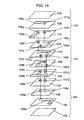
- Fig. 14 is an exploded perspective view of another conventional noise filter disclosed in Japanese Patent Laid-Open Publication No.5-101950.
- the filter includes a coil assembly 101 made of magnetic sheets having large magnetic permeability and lead assemblies 102 and 103 made of magnetic sheets having small magnetic permeability.
- the lead assemblies 102 and 103 are provided on both, upper and lower, surfaces of the coil assembly 101.
- a first coil consists mainly of conductors 108a and 109a which are electrically connected to each other with a through-hole 106a.
- a second coil consists mainly of conductors 108b and 109b which are electrically connected to each other with a through-hole 106c.
- the noise filter has a small impedance for a normal component at the lead assemblies, thus suppressing a common mode noise without seriously disturbing a signal.
- the conventional noise filter suppresses the common mode noise by having a small impedance for the normal component throughout the coil.
- the noise filter further suppresses the common mode noise by having a large impedance for a common component in the coil assembly 101 including the sheets having the large magnetic permeability.
- the filter needs to include tens of coil patterns of less than one turn stacked. This structure increases a number of production steps including fabricating through-holes and printing coil patterns, and they are assembled complicatedly. Such an intricate structure of the noise filter often suffers from open faults and short-circuits, hence having a declining efficiency of its production.
- a noise filter has a large impedance in a common mode and thus has a large noise attenuation in the common mode.
- the filter includes a magnetic body including first and second magnetic sheets, external electrodes provided on both side surfaces of the magnetic body, first and second inner conductors having spiral shapes of one or more turns and provided on the first magnetic sheet, third and fourth inner conductors having spiral shapes of one or more turns and provided on the second magnetic sheet, lead electrodes provided at one end of the first magnetic sheet for connecting a first end of the first inner conductor to one of the external electrodes and for connecting a first end of the second inner conductor to one of the external electrodes, respectively, and lead electrodes provided at one end of the second magnetic sheet for connecting a first end of the third inner conductor to one of the external electrodes and for connecting a first end of the fourth inner conductor to one of the external electrodes, respectively.
- the first and second inner conductors are not short-circuited from each other, and the third and fourth inner conductors are not short-circuited from each other.
- a second end of the first inner conductor is located near a second end of the second inner conductor, and a second end of the third inner conductor is located near a second end of the fourth inner conductor.
- the second end of the first inner conductor is electrically connected to the second end of the third inner conductor.
- the second end of the second inner conductor is electrically connected to the second end of the fourth inner conductor.
- Figs. 1A and 1B are plan views of a noise filter according to exemplary embodiment 1 of the present invention.
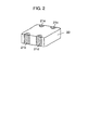
- Fig. 2 is a perspective view of the noise filter.
- First magnetic sheets 11a and 11b have a first inner conductor 12 and a second inner conductor 13 provided on the upper surface thereof, respectively.
- the first magnetic sheets 11a and 11b have lead electrodes 14a to 14d provided at one side thereof and via-electrodes 15a to 15d provided at central regions thereof.
- the first magnetic sheets 11a and 11b are made of magnetic material, such as ferrite.
- the first inner conductor 12 and the second inner conductor 13 are made of electrically conductive material, such as silver, having a spiral shape of more than one turn, and spaced from each other for avoiding short-circuit.
- the inner conductors 12 and 13 are identical in the direction of the spiral from an upper point of view.
- the first inner conductor 12 and the second inner conductor 13 have one ends connected to the lead electrodes 14a to 14d and the other ends, i.e., the center of the spiral connected to the via-electrodes 15a to 15d.
- the first inner conductor 12 on the first magnetic sheet 11a is connected to the lead electrode 14a, while the second inner conductor 13 is connected to the lead electrode 14c.
- the first inner conductor 12 on the other first magnetic sheet 11b is connected to the lead electrode 14b, while the second inner conductor 13 is connected to the lead electrode 14d.
- the lead electrodes 14a to 14d are made of electrically conductive material, such as silver.
- the via-electrode 15a is provided on the first magnetic sheet 11a while the via-electrode 15b is provided on the other first magnetic sheet 11b.
- the via-electrodes 15a and 15b are connected to each other via a through-hole 16a provided in the first magnetic sheet 11b.
- the first inner conductors 12 on the sheets are connected to each other, providing a first coil 17.
- the via-electrode 15c is provided on the first magnetic sheet 11a, while the via-electrode 15d is provided on the other first magnetic sheet 11b.
- the via-electrodes 15c and 15d are connected to each other via a through-hole 16b provided in the first magnetic sheet 11b.
- the first inner conductors 13 on the sheets are connected to each other, providing a second coil 18.
- the via-electrodes 15a and 15c are located close to but spaced from each other for avoiding short-circuit, and the via-electrodes 15b and 15d are located close to but spaced from each other for avoiding short-circuit.
- the upper surface of the first magnetic sheet 11b on which the first inner conductor 12 and the second inner conductor 13 are provided and the lower surface of the first magnetic sheet 11a may be covered with dummy sheets 19 (not shown) if desired. Those sheets are stacked, thus providing a magnetic body 20.
- the magnetic body 20 has external electrodes 21a and 21c provided on one side thereof.
- the external electrodes 21a and 21c are connected to the lead electrodes 14a and 14c, respectively.
- the magnetic body 20 has external electrodes 21b and 21d provided on the opposite side thereof and connected to the lead electrodes 14b and 14d, respectively.
- Figs. 3A to 3C and Figs. 4A to 4D are perspective views for illustrating the procedure of fabricating the noise filter of embodiment 1.
- the first magnetic sheets 11a and 11b having a square shape are prepared from mixture of oxide of ferrite powder and resin.
- the magnetic sheet 11b are perforated by laser or punching process to have the first and second, through-holes 16a and 16b at the center of each spiral corresponding to the respective other ends of the first inner conductor 12 and the second inner conductor 13.
- the first through-hole 16a and the second through-hole 16b are located near each other.
- the first inner conductors 12 and the second inner conductors 13 having the spiral shape of more than one turn are provided by printing or plating on the first magnetic sheet 11b where the through-holes 16a and 16b are provided, as shown in Fig. 3B.
- the second inner conductor 13 is located at the inward side of the first inner conductor 12 for avoiding short-circuit.
- the via-electrodes 15b and 15d (not shown) are then provided at the respective other ends of the first and second inner conductors 12 and 13. As the other ends of the via-electrodes 15b and 15d.
- the electrodes 15b and 15d are connected to the through-holes 16a and 16b, respectively.
- the respective one ends of the first inner conductor 12 and the second inner conductor 13 are connected to the lead electrodes 14b and 14d (not shown).
- the first through-hole 16a and the second through-hole 16b are filled with electrically conductive material, such as silver.
- first inner conductors 12 and the second inner conductors 13 having a spiral shape of more than one turn are provided by printing or plating on the first magnetic sheet 11a.
- the first magnetic sheet 11b is placed on the first magnetic sheet 11a, as shown in Fig. 3C. More specifically, a dummy magnetic sheet 19, the first magnetic sheet 11a having the first inner conductor 12 and the second inner conductor 13 provided thereon, the other first magnetic sheet 11b having the first inner conductor 12 and the second inner conductor 13 provided thereon, and another dummy magnetic sheet 19 are placed one over the other in this order. Respective upper surfaces of the first inner conductor 12 and the second inner conductor 13 provided on the first magnetic sheet 11b and the lower surface of the first magnetic sheet 11a may be covered with a desired number of the dummy magnetic sheets 19.
- the first inner conductors 12 are electrically connected to each other via the first through-hole 16a, while the second inner conductors 13 are electrically connected to each other via the second through-hole 16b. Meanwhile, the inner conductors 12 and 13 and the lead electrodes 14a to 14d (not shown) may be fabricated by any process, such as printing, plating, vapor depositing, or sputtering.
- Each block shown in Fig. 4B includes the first inner conductors 12 and the second inner conductors 13.
- the block 22 has the lead electrodes 14a and 14c exposed at one side and the lead electrodes 14b and 14d exposed at the opposite side.
- the block 22 is then baked at a predetermined temperature for a predetermined period of time, thus providing the magnetic body 20.
- the magnetic body 20 is deburred by barrel processing, as shown in Fig. 4C.
- the external electrodes 21a to 21d made of electrically conductive material, such as silver, are provided on the magnetic body 20 and connected to the lead electrodes 14a to 14d, respectively, thus providing the a noise filter.
- the external electrodes 21a to 21d may be nickel-plated on the conductive, silver surface or finished with plating of low-melting point metal, such as tin or soldering alloy, over the nickel-plated surface.
- the magnetic body 20 may be immersed into fluoric silane coupling agent liquid under a vacuum atmosphere. This permits tiny pores in the magnetic body 20 to be filled with the volatile fluoric silane coupling agent, hence improving a resistance to moisture of the noise filter.
- the noise filter of embodiment 1 allows the first conductor 12 and the second conductor 13 on the first magnetic sheets 11a and 11b, which affect each other, to be favorably lengthened.
- plural first magnetic sheets 11a and 11b, each having the first inner conductor 12 and the second inner conductor 13, are provided in a stacked assembly, the total lengths of respective portions of the first inner conductors 12 and the second inner conductors 13 which influence each other can further increase. This increases the impedance for a noise in a common mode. As the result, the noise filter has a large attenuation of noise components in the common mode.
- the noise filter of embodiment 1 can have a larger impedance in the common mode than the conventional noise filter shown in Fig. 7.
- the currents flowing in the first coil 17 and the second coil 18 in the same direction increases the impedance of the first inner conductor 12 and the second inner conductor 13, thus attenuating the noise in the common mode.
- the first inner conductor 12 and the second inner conductor 13 have lengths greater than that of any conventional scroll or zigzag shape, hence increasing the impedance in the common mode.
- the first inner conductor 12 and the second inner conductor 13 generate magnetic fluxes emphasized by each other, hence increasing the impedance in the common mode.
- the number of the first magnetic sheets having the first inner conductor 12 and the second inner conductor 13 provided thereon is not limited to two. More than three of the first magnetic sheets further increase the impedance in the common mode.
- the distance between the conductors is not short although the conductors have the spiral shapes. Accordingly, magnetic fluxes generated by the conductors may not be emphasized by each other, hence hardly increasing the impedance in the common mode.
- Figs. 5A to 5C are plan views of a noise filter of embodiment 2 of the present invention. Like components are denote by like numerals as those of embodiment 1 and will be explained in no more detail.
- a first magnetic sheet 11b has a first inner conductor 12 and a second inner conductor 13 provided on the upper surface thereof.
- a second magnetic sheet 25 having a third inner conductor 24 connected to the first inner conductor 12 is provided on the upper surface of the first magnetic sheet 11b.
- a third magnetic sheet 27 having a fourth inner conductor 26 connected to the second inner conductor 13 is provided on the lower surface of the first magnetic sheet 11b.
- the fourth inner conductor 26 may be provided not on the third magnetic sheet 27 but on a dummy magnetic sheet 19.
- This arrangement allows the third inner conductor 24 on the second magnetic sheet 25 and the fourth inner conductor 26 on the third magnetic sheet 27 to be spaced from each other by the first magnetic sheet 11b having the first inner conductor 12 and the second inner conductor 13 provided thereon. Therefore, even when currents flow in the first coil 17 and the second coil 18 in different directions, magnetic fluxes generated by the first coil 17 and the second coil 18 can hardly decrease each other. This increases an impedance in a normal mode.
- the inner conductors 12 and 13 on the first magnetic sheet 11b has a large impedance in a common mode as explained in embodiment 1.
- the noise filter shown in Fig. 5 has a large impedance both in the common mode and the normal mode.
- the first coil 17 is composed mainly of the first inner conductor 12 and the third inner conductor 24, while the second coil 18 is composed mainly of the second inner conductor 13 and the fourth inner conductor 26.
- the third inner conductor 24 and the fourth inner conductor 26 have spiral shapes, such as screw or coaxial configuration. This shape generates a magnetic flux more than a linear shape, thus increasing the impedance in the normal mode.
- the first coil 17 and the second coil 18 have the same length, i.e., the distance between the lead electrodes by appropriately adjusting the length of the third inner conductor 24 on the second magnetic sheet 25 and the length of the fourth inner conductor 26 on the third magnetic sheet 27. This adjustment allows the first coil 17 and the second coil 18 to have the same resistances and impedances.
- a non-magnetic material is provided on at least one of the upper surface the third inner conductor 24 and the lower surface of the fourth inner conductor 26.
- This arrangement decreases the magnetic flux generated by the third inner conductor 24 and/or the fourth inner conductor 26. Accordingly, the impedance the third inner conductor 24 and/or the fourth inner conductor 26 become small in both the normal mode and the common mode. As the result, the impedances of the first inner conductor 12 and the second inner conductor 13 on the first magnetic sheet 11b can remain stable in both the normal mode and the common mode.
- the third inner conductor 24 and the fourth inner conductor 26 covered with the non-magnetic material can have a large insulating performance and a large resistance against moisture.
- the second magnetic sheet 25 having only the third inner conductor 24 provided thereon may be provided on respective lower surfaces of the first inner conductor 12 and the second inner conductor 13 provided on the first magnetic sheet 11b.
- the third magnetic sheet 27 having only the fourth inner conductor 26 may be provided on the respective upper surfaces of the first inner conductor 12 and the second inner conductor 13 provided on the first magnetic sheet 12.
- the conventional noise filter shown in Fig. 13 has the first coil pattern 2 provided at an outer side of the second coil pattern 3, the first and second coils 4 and 5 cannot have the same resistances and impedances.
- the number of the first magnetic sheet 11b the first inner conductor 12 and the second inner conductor 13 provided thereon is not limited to one but may be provided two or more.
- the noise filter of embodiment 2 similarly to that of embodiment 1, can have the resistance against moisture, upon having the magnetic sheets impregnated with silane coupling agent.
- a lead line from a head set of a mobile telephone often includes a pair of signal lines, cables.
- a high-frequency signal component of a carrier may often interfere a main signal in the same phase, thus acting as a radiant noise. Therefore, a high-frequency noise in a common mode is input in the signal lines.
- the main signal including a voice signal and a control signal for the mobile telephone are in a normal mode.
- the main signal in the normal mode is interfered by the high-frequency noise in the common mode since the signal contains a low frequency component induced by a non-linear device and a static capacitance in a circuit.
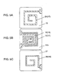
- Fig. 6A illustrates an application of the noise filter of embodiments 1 and 2.
- the noise filter 33 of the invention has the external electrodes 21a to 21d shown in Fig. 1 connected via the signal lines 34 of a head set coupled to a headphone 35. More specifically, the first coil 17 and the second coil 18 of the noise filter 33 are connected to the signal lines 34, respectively.
- a signal of a TDMA mobile telephone system includes a 217Hz burst signal 32 carried on a (TDMA) carrier 31 at 900MHz.
- the 217Hz component is detected and may be superimposed on the voice signal in the normal mode, thus creating a audible noise.
- the noise can be attenuated by decreasing an amplitude of a common mode current induced in the normal mode.
- Fig. 6C illustrates a filtering effect of the noise filter of embodiments 1 and 2, i.e., the relationship between frequency and attenuation.
- the noise in the common mode and the normal mode is attenuated at 900 MHz of the carrier. Accordingly, the 217Hz component of the burst signal 32 on the carrier of 900MHz which creates the audible noise can be eliminated.
- the filter Since the signal lines in radio communications device, such as a mobile telephone, are connected to the first coil 17 and the second coil 18 of the noise filter of embodiments 1 and 2, the filter has a large impedance in both the common mode and the normal mode, and thus attenuates a noise component in the normal mode. Accordingly, the audible noise on the signal lines , audio lines, can be attenuated.
- Fig. 7 is an exploded perspective view of a noise filter according to exemplary embodiment 3 of the present invention.
- the noise filter includes a first insulating layer 121, a first conductor 127 having a spiral shape provided on an upper surface of the first insulating layer 121, and a second conductor 128 having a spiral shape provided substantially parallel with the first conductor 127 on the upper surface of the first insulating layer 121.
- the first conductor 127 and the second conductor 128 are arranged of a double spiral configuration.
- the noise filter further includes a second insulating layer 122 provided on the upper surface of the first insulating layer 121, through-holes 131a and 131b provided in the second insulating layer 122 and filled with electrically conductive material, a third conductor 129 having a spiral shape provided on an upper surface of the second insulating layer 122, and a fourth conductor 140 having a spiral shape provided substantially parallel to the third conductor 129 on the upper surface of the second insulating layer 122.
- the first conductor 127 and the second conductor 128 are located between the first insulating layer 121 and the second insulating layer 122.
- the third conductor 129 and the fourth conductor 130 have are arranged in a double spiral configuration.
- the first conductor 129 is electrically connected via the through-hole 131a to the first conductor 127, while the fourth conductor 130 is electrically connected via the through-hole 131b to the second conductor 128.
- the first to fourth conductors 127 to 130 may be fabricated by a printing process or preferably by a plating process forming the spiral shape precisely and accurately.
- the second insulating layer 122 has a magnetic permeability not larger than the first insulating layer 121 and a third insulating layer 123.
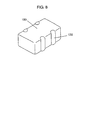
- Fig. 8 is a perspective view of the noise filter of embodiment 3.
- the noise filter 133 includes four external electrodes 132 electrically connected to the first to fourth conductors 127 to 130, respectively.
- the four conductors 127 to 130 are arranged of spiral shapes.
- the first conductor 127 and the second conductor 128 extend substantially in parallel with each other, and the third conductor 129 and the fourth conductor 130 extend substantially in parallel with each other. Therefore, the distance between two adjacent conductors of the spiral shape on the insulating layer can be reduced.
- a magnetic path on the insulating layer can be increased. Since -the magnetic fluxes generated by the conductors emphasize each other, the filter has a large impedance in a common mode. Additionally, the magnetic permeability of the second insulating layer 122 having the through-holes 131a and 131b is not larger than that of other insulating layers.
- the second insulating layer 122 having the lower magnetic permeability is positioned between the conductors 127 and 128 and between the conductors 129 and 130. This arrangement emphasizes the magnetic field generated by each conductor, thus effectively attenuating a noise in the common mode.
- the filter further attenuates the noise in the common mode.
- the insulating layers and the insulating layer having the small magnetic permeability are baked together as a single unit, as shown in Fig. 8.
- the second insulating layer 122 having the lower permeability may be made of Ni-Zn-Cu-Co ferrite.
- the second insulating layer 122 may be made of non-magnetic material for further attenuation of noises.
- the non-magnetic material is preferably selected from forsterite glass, alumina-glass dielectric, and Zn-Cu ferrite.
- Fig. 9 is an exploded perspective view of a noise filter according to exemplary embodiment 4 of the present invention.
- Fig. 10 is a top view of a first insulating layer of the noise filter.
- the first insulating layer 121 has a magnetic permeability identical to that of a second insulating layer 122 and a third insulating layer 123.
- An insulating layer 124 having a small magnetic permeability is provided at least either between a first conductor 127 and a second conductor 128 both patterned by, e.g. a vapor deposition process or between a third conductor 129 and a fourth conductor 130 both patterned by the same process.
- the magnetic permeability of the insulating layer 124 is not larger than that of the insulating layers 121 to 123.
- like components are denoted by like numerals as those of embodiment 3 and will be explained in no more detail.
- the first to fourth conductors 127 to 130 are arranged of spiral shapes.
- the first conductor 127 and the second conductor 128 extend substantially parallel with each other, while the third conductor 129 and the fourth conductor 130 extend substantially parallel with each other. Therefore, the distance between two adjacent conductors of the spiral shapes on the insulating layer can be reduced. Since the conductors are arranged of spiral shapes, a magnetic path on each insulating layer can be increased. Since the magnetic fluxes generated by the conductors emphasize each other, the filter has a large impedance in the common mode. Additionally, the insulating layers 124 having the smaller magnetic permeability are positioned between the conductors 127 and 128 and between the conductors 129 and 130, respectively. This arrangement emphasizes a magnetic flux generated by each conductor, thus effectively attenuating a noise in the common mode.
- the filter attenuates noises more.
- Material of the insulating layer 124 having the smaller magnetic permeability may be selected from those described in embodiment 3 with equal effects.
- FIG. 11 is an exploded perspective view of a noise filter according to exemplary embodiment 5 of the present invention.
- a magnetic permeability of a second insulating layer 122 is equal to that of a first insulating layer 121 and a third insulating layer 123.
- a insulating layer 125 having a smaller magnetic permeability is provided over at least either the first conductor 127 and the second conductor 128 both patterned by, e.g. a printing process or the third conductor 129 and the fourth conductor 130 both patterned by the same process.
- the magnetic permeability of the insulating layer 125 is not larger than that of the insulating layers 121 to 123.
- like components are denoted by like numerals as those of embodiment 3 and will be explained in no more detail.
- Each of the first to fourth conductors 127 to 130 are arranged of a spiral shape.
- the first conductor 127 and the second conductor 128 extend substantially parallel with each other, while the third conductor 129 and the fourth conductor 130 extend substantially parallel with each other. Therefore, the distance between two adjacent conductors of the spiral shape on the insulating layer can be reduced. Since the conductors are arranged of spiral shapes, a magnetic path on the insulating layer can be increased. Since the magnetic fluxes generated by the conductors emphasize each other, the filter has a large impedance in a common mode. Additionally, the insulating layer 125 has the magnetic permeability not larger than the other insulating layers.
- Two of the insulating layers 125 having smaller permeability are positioned between the conductors 127 and 128 and between the conductors 129 and 130, respectively. This arrangement emphasizes a magnetic field generated by the conductors, thus effectively attenuating a noise in the common mode.
- the filter attenuates noises more.
- Material of the insulating layer 125 having the smaller magnetic permeability may be selected from those described in embodiment 3 with equal effects.
- Fig. 12 is an exploded perspective view of a noise filter according to exemplary embodiment 6 of the present invention.
- a magnetic permeability of a second insulating layer 122 is equal to that of a first insulating layer 121 and a third insulating layer 123.
- a insulating layer 126 having a small magnetic permeability is provided between the second conductor 128 and the third conductor 129 patterned by e.g. a plating process.
- the magnetic permeability of the insulating layer 126 is not larger than that of the insulating layers 121 to 123.
- like components are denoted by like numerals as those of embodiment 3 and will be explained in no more detail.
- the second and third conductors 128 and 129 are arranged in a spiral shape.
- the magnetic path on the insulating layer can thus be lengthened.
- This arrangement emphasizes a magnetic field generated by the conductors 128 and 129, hence having a large impedance in a common mode.
- the insulating layer 126 has the magnetic permeability not larger than the other insulating layers. Since the second conductor 128 and the third conductor 129 are positioned to sandwich the insulating layer 126 having the smaller permeability, the filter emphasizes magnetic fluxes generated by the conductors. As the result, a noise in the common mode can effectively be attenuated.
- the filter attenuates noises more.
- Material of the insulating layer 125 having the smaller magnetic permeability may be selected from those described in embodiment 3 with equal effects.
- a noise filter according to the present invention includes a first and second inner conductors which influence each other and are provided on a magnetic sheet, and the conductors can be long. Such magnetic sheets are provided, the first and second inner conductors influencing each other can be longer, thus providing the filter with a large impedance for noises in a common mode.
Landscapes
- Engineering & Computer Science (AREA)
- Power Engineering (AREA)
- Microelectronics & Electronic Packaging (AREA)
- Coils Or Transformers For Communication (AREA)
- Filters And Equalizers (AREA)
Abstract
Description
- The present invention relates to a noise filter and an electronic device using the filter for a use in a mobile telephone and a data apparatus for suppressing noise components.
- Figs. 13A to 13G are plan views of a multi-layer transformer which functions as a conventional noise filter disclosed in Japanese Patent Laid-open Publication No.60-257709. The transformer includes
magnetic sheets 1,first coil patterns 2, andsecond coil patterns 3. Thefirst coil patterns second coil patterns 3 provided on eachmagnetic sheet 1 are arranged parallel to each other and have spiral shapes of 0.25 to 0.75 turn from an upper point of view. - As shown in Figs. 13B to 13F, the
magnetic sheets 1 are stacked, and thefirst coil patterns 2 are connected to one another to form afirst coil 4. Thesecond coil patterns 3 are connected to one another to form asecond coil 5. Via-electrodes 6 are provided at both end of eachfirst coil pattern 2 on eachmagnetic sheet 1, and via-electrodes 7 are provided at both ends of eachsecond coil pattern 3. The via-electrodes magnetic sheet 1 is electrically connected with a through-hole 8 in amagnetic sheet 1 to itscorresponding electrodes magnetic sheet 1. Both ends of the first andsecond coils coil patterns lowermost sheets 1 are connected tolead electrodes 9a to 9d. Thecoil patterns lowermost sheets 1 have a spiral shape of 0.5 turn except their ends around to thelead electrodes 9a to 9d. - As shown in Figs. 13A and 13G,
magnetic sheets 1 are provided on thefirst coil 4 and thesecond coil 5. - The
first coil 4, thesecond coil 5, and themagnetic sheets 1 are stacked together to provide a noise filter. - In the conventional noise filter, when a noise in a common mode is applied to the
coils - However, the conventional noise filter may hardly increase the impedance in the common mode up to a desired level for suppressing noise components. Since the
first coil pattern 2 and the second coil pattern on eachmagnetic sheet 1 have the spiral shapes of 0.25 turn to 0.75 turn, the coil patterns influence each other are short. Accordingly, magnetic flux generated by thefirst coil 4 and thesecond coil 5 is too small to emphasize each other, and thus, the filter does not have a large impedance in the normal mode of the filter. - Fig. 14 is an exploded perspective view of another conventional noise filter disclosed in Japanese Patent Laid-Open Publication No.5-101950. The filter includes a
coil assembly 101 made of magnetic sheets having large magnetic permeability andlead assemblies lead assemblies coil assembly 101. A first coil consists mainly ofconductors hole 106a. Similarly, a second coil consists mainly ofconductors hole 106c. The noise filter has a small impedance for a normal component at the lead assemblies, thus suppressing a common mode noise without seriously disturbing a signal. - The conventional noise filter suppresses the common mode noise by having a small impedance for the normal component throughout the coil. The noise filter further suppresses the common mode noise by having a large impedance for a common component in the
coil assembly 101 including the sheets having the large magnetic permeability. In order to have the large impedance for the common component, the filter needs to include tens of coil patterns of less than one turn stacked. This structure increases a number of production steps including fabricating through-holes and printing coil patterns, and they are assembled complicatedly. Such an intricate structure of the noise filter often suffers from open faults and short-circuits, hence having a declining efficiency of its production. - A noise filter has a large impedance in a common mode and thus has a large noise attenuation in the common mode. The filter includes a magnetic body including first and second magnetic sheets, external electrodes provided on both side surfaces of the magnetic body, first and second inner conductors having spiral shapes of one or more turns and provided on the first magnetic sheet, third and fourth inner conductors having spiral shapes of one or more turns and provided on the second magnetic sheet, lead electrodes provided at one end of the first magnetic sheet for connecting a first end of the first inner conductor to one of the external electrodes and for connecting a first end of the second inner conductor to one of the external electrodes, respectively, and lead electrodes provided at one end of the second magnetic sheet for connecting a first end of the third inner conductor to one of the external electrodes and for connecting a first end of the fourth inner conductor to one of the external electrodes, respectively. The first and second inner conductors are not short-circuited from each other, and the third and fourth inner conductors are not short-circuited from each other. A second end of the first inner conductor is located near a second end of the second inner conductor, and a second end of the third inner conductor is located near a second end of the fourth inner conductor. The second end of the first inner conductor is electrically connected to the second end of the third inner conductor. The second end of the second inner conductor is electrically connected to the second end of the fourth inner conductor.
-
- Figs. 1A and 1B are plan views of a noise filter according to
exemplary embodiment 1 of the present invention. - Fig. 2 is a perspective view of the noise filter of
embodiment 1. - Figs. 3A to 3C are perspective views of for illustrating a procedure of
fabricating the noise filter of
embodiment 1. - Figs. 4A to 4D are perspective views for illustrating a procedure of
fabricating the noise filter of
embodiment 1. - Figs. 5A to 5C are plan view of a noise filter according to
exemplary embodiment 2 of the invention. - Fig. 6A illustrates a use of the noise filter of
embodiment 1. - Fig. 6B shows a waveform of a carrier on a pair of signal lines of a mobile telephone.
- Fig. 6C illustrates the relationship between frequency and attenuation
of the noise filter of
embodiments - Fig. 7 is an exploded perspective view of a noise filter according to
exemplary embodiment 3 of the invention. - Fig. 8 is a perspective view of the noise filter of
embodiment 3. - Fig. 9 is an exploded perspective view of a noise filter according to
exemplary embodiment 4 of the invention. - Fig. 10 is a top view of a first insulating layer of the noise filter of
embodiment 4. - Fig. 11 is an exploded perspective view of a noise filter according to
exemplary embodiment 5 of the invention. - Fig. 12 is an exploded perspective view of a noise filter according to
exemplary embodiment 6 of the invention. - Figs. 13A to 13G are plan views of a conventional noise filter.
- Fig. 14 is an exploded perspective view of the conventional noise filter.
-
- Figs. 1A and 1B are plan views of a noise filter according to
exemplary embodiment 1 of the present invention. Fig. 2 is a perspective view of the noise filter. Firstmagnetic sheets inner conductor 12 and a secondinner conductor 13 provided on the upper surface thereof, respectively. The firstmagnetic sheets electrodes 14a to 14d provided at one side thereof and via-electrodes 15a to 15d provided at central regions thereof. The firstmagnetic sheets - The first
inner conductor 12 and the secondinner conductor 13 are made of electrically conductive material, such as silver, having a spiral shape of more than one turn, and spaced from each other for avoiding short-circuit. Theinner conductors - The first
inner conductor 12 and the secondinner conductor 13 have one ends connected to thelead electrodes 14a to 14d and the other ends, i.e., the center of the spiral connected to the via-electrodes 15a to 15d. - The first
inner conductor 12 on the firstmagnetic sheet 11a is connected to thelead electrode 14a, while the secondinner conductor 13 is connected to thelead electrode 14c. Similarly, the firstinner conductor 12 on the other firstmagnetic sheet 11b is connected to thelead electrode 14b, while the secondinner conductor 13 is connected to thelead electrode 14d. Thelead electrodes 14a to 14d are made of electrically conductive material, such as silver. - The via-
electrode 15a is provided on the firstmagnetic sheet 11a while the via-electrode 15b is provided on the other firstmagnetic sheet 11b. The via-electrodes hole 16a provided in the firstmagnetic sheet 11b. Thus, the firstinner conductors 12 on the sheets are connected to each other, providing afirst coil 17. - Similarly, the via-
electrode 15c is provided on the firstmagnetic sheet 11a, while the via-electrode 15d is provided on the other firstmagnetic sheet 11b. The via-electrodes hole 16b provided in the firstmagnetic sheet 11b. Thus, the firstinner conductors 13 on the sheets are connected to each other, providing asecond coil 18. - The via-
electrodes electrodes - The upper surface of the first
magnetic sheet 11b on which the firstinner conductor 12 and the secondinner conductor 13 are provided and the lower surface of the firstmagnetic sheet 11a may be covered with dummy sheets 19 (not shown) if desired. Those sheets are stacked, thus providing amagnetic body 20. - The
magnetic body 20 hasexternal electrodes external electrodes lead electrodes magnetic body 20 hasexternal electrodes lead electrodes - A procedure of fabricating the noise filter of
embodiment 1 will be described. - Figs. 3A to 3C and Figs. 4A to 4D are perspective views for illustrating the procedure of fabricating the noise filter of
embodiment 1. - First, the first
magnetic sheets - Then, as shown in Fig. 3A, the
magnetic sheet 11b are perforated by laser or punching process to have the first and second, through-holes inner conductor 12 and the secondinner conductor 13. The first through-hole 16a and the second through-hole 16b are located near each other. - The first
inner conductors 12 and the secondinner conductors 13 having the spiral shape of more than one turn are provided by printing or plating on the firstmagnetic sheet 11b where the through-holes inner conductor 13 is located at the inward side of the firstinner conductor 12 for avoiding short-circuit. The via-electrodes inner conductors electrodes electrodes holes inner conductor 12 and the secondinner conductor 13 are connected to thelead electrodes - The first through-
hole 16a and the second through-hole 16b are filled with electrically conductive material, such as silver. - Similarly, the first
inner conductors 12 and the secondinner conductors 13 having a spiral shape of more than one turn are provided by printing or plating on the firstmagnetic sheet 11a. - Then, the first
magnetic sheet 11b is placed on the firstmagnetic sheet 11a, as shown in Fig. 3C. More specifically, a dummymagnetic sheet 19, the firstmagnetic sheet 11a having the firstinner conductor 12 and the secondinner conductor 13 provided thereon, the other firstmagnetic sheet 11b having the firstinner conductor 12 and the secondinner conductor 13 provided thereon, and another dummymagnetic sheet 19 are placed one over the other in this order. Respective upper surfaces of the firstinner conductor 12 and the secondinner conductor 13 provided on the firstmagnetic sheet 11b and the lower surface of the firstmagnetic sheet 11a may be covered with a desired number of the dummymagnetic sheets 19. - The first
inner conductors 12 are electrically connected to each other via the first through-hole 16a, while the secondinner conductors 13 are electrically connected to each other via the second through-hole 16b. Meanwhile, theinner conductors lead electrodes 14a to 14d (not shown) may be fabricated by any process, such as printing, plating, vapor depositing, or sputtering. - Then, the stacked assembly are divided into noise filter blocks 22 by dicing, as shown in Fig. 4A. Each block shown in Fig. 4B includes the first
inner conductors 12 and the secondinner conductors 13. Theblock 22 has thelead electrodes lead electrodes - The
block 22 is then baked at a predetermined temperature for a predetermined period of time, thus providing themagnetic body 20. - The
magnetic body 20 is deburred by barrel processing, as shown in Fig. 4C. - Finally, the
external electrodes 21a to 21d made of electrically conductive material, such as silver, are provided on themagnetic body 20 and connected to thelead electrodes 14a to 14d, respectively, thus providing the a noise filter. - The
external electrodes 21a to 21d may be nickel-plated on the conductive, silver surface or finished with plating of low-melting point metal, such as tin or soldering alloy, over the nickel-plated surface. - Alternatively, prior to the nickel-plating over the conductive or silver surface, the
magnetic body 20 may be immersed into fluoric silane coupling agent liquid under a vacuum atmosphere. This permits tiny pores in themagnetic body 20 to be filled with the volatile fluoric silane coupling agent, hence improving a resistance to moisture of the noise filter. - The noise filter of
embodiment 1 allows thefirst conductor 12 and thesecond conductor 13 on the firstmagnetic sheets magnetic sheets inner conductor 12 and the secondinner conductor 13, are provided in a stacked assembly, the total lengths of respective portions of the firstinner conductors 12 and the secondinner conductors 13 which influence each other can further increase. This increases the impedance for a noise in a common mode. As the result, the noise filter has a large attenuation of noise components in the common mode. - When currents flow in the
first coil 17 and thesecond coil 18 in the same direction from an upper point of view, the firstinner conductors magnetic body 20. As the result, the noise filter ofembodiment 1 can have a larger impedance in the common mode than the conventional noise filter shown in Fig. 7. The currents flowing in thefirst coil 17 and thesecond coil 18 in the same direction increases the impedance of the firstinner conductor 12 and the secondinner conductor 13, thus attenuating the noise in the common mode. - Since having the spiral shapes of more than one turn, the first
inner conductor 12 and the secondinner conductor 13 have lengths greater than that of any conventional scroll or zigzag shape, hence increasing the impedance in the common mode. - Additionally, upon spaced from each other by a minimum distance for avoiding short-circuit, the first
inner conductor 12 and the secondinner conductor 13 generate magnetic fluxes emphasized by each other, hence increasing the impedance in the common mode. - Moreover, the number of the first magnetic sheets having the first
inner conductor 12 and the secondinner conductor 13 provided thereon is not limited to two. More than three of the first magnetic sheets further increase the impedance in the common mode. - In case that the second
inner conductor 13 is not placed inside or outside the spiral shape of the firstinner conductor 12, that is, is placed independently from each other, the distance between the conductors is not short although the conductors have the spiral shapes. Accordingly, magnetic fluxes generated by the conductors may not be emphasized by each other, hence hardly increasing the impedance in the common mode. - Figs. 5A to 5C are plan views of a noise filter of
embodiment 2 of the present invention. Like components are denote by like numerals as those ofembodiment 1 and will be explained in no more detail. - As shown in Figs. 5A to 5C, a first
magnetic sheet 11b has a firstinner conductor 12 and a secondinner conductor 13 provided on the upper surface thereof. A secondmagnetic sheet 25 having a thirdinner conductor 24 connected to the firstinner conductor 12 is provided on the upper surface of the firstmagnetic sheet 11b. A thirdmagnetic sheet 27 having a fourthinner conductor 26 connected to the secondinner conductor 13 is provided on the lower surface of the firstmagnetic sheet 11b. The fourthinner conductor 26 may be provided not on the thirdmagnetic sheet 27 but on a dummymagnetic sheet 19. - This arrangement allows the third
inner conductor 24 on the secondmagnetic sheet 25 and the fourthinner conductor 26 on the thirdmagnetic sheet 27 to be spaced from each other by the firstmagnetic sheet 11b having the firstinner conductor 12 and the secondinner conductor 13 provided thereon. Therefore, even when currents flow in thefirst coil 17 and thesecond coil 18 in different directions, magnetic fluxes generated by thefirst coil 17 and thesecond coil 18 can hardly decrease each other. This increases an impedance in a normal mode. - When currents flowing in the
first coil 17 and thesecond coil 18 in the same direction, theinner conductors magnetic sheet 11b has a large impedance in a common mode as explained inembodiment 1. - In other words, the noise filter shown in Fig. 5 has a large impedance both in the common mode and the normal mode.
- The
first coil 17 is composed mainly of the firstinner conductor 12 and the thirdinner conductor 24, while thesecond coil 18 is composed mainly of the secondinner conductor 13 and the fourthinner conductor 26. The thirdinner conductor 24 and the fourthinner conductor 26 have spiral shapes, such as screw or coaxial configuration. This shape generates a magnetic flux more than a linear shape, thus increasing the impedance in the normal mode. - The
first coil 17 and thesecond coil 18 have the same length, i.e., the distance between the lead electrodes by appropriately adjusting the length of the thirdinner conductor 24 on the secondmagnetic sheet 25 and the length of the fourthinner conductor 26 on the thirdmagnetic sheet 27. This adjustment allows thefirst coil 17 and thesecond coil 18 to have the same resistances and impedances. - Moreover, in case that the third
inner conductor 24 and the fourthinner conductor 26 allows thefirst coil 17 and thesecond coil 18 to have the same resistances and impedances, a non-magnetic material is provided on at least one of the upper surface the thirdinner conductor 24 and the lower surface of the fourthinner conductor 26. This arrangement decreases the magnetic flux generated by the thirdinner conductor 24 and/or the fourthinner conductor 26. Accordingly, the impedance the thirdinner conductor 24 and/or the fourthinner conductor 26 become small in both the normal mode and the common mode. As the result, the impedances of the firstinner conductor 12 and the secondinner conductor 13 on the firstmagnetic sheet 11b can remain stable in both the normal mode and the common mode. - Nothing may be provided on the upper surface of the third
inner conductor 24 and/or on the lower surface of the fourthinner conductor 26 as the non-magnetic material. However, the thirdinner conductor 24 and the fourthinner conductor 26 covered with the non-magnetic material, such as glass or resin, can have a large insulating performance and a large resistance against moisture. - Alternatively, the second
magnetic sheet 25 having only the thirdinner conductor 24 provided thereon may be provided on respective lower surfaces of the firstinner conductor 12 and the secondinner conductor 13 provided on the firstmagnetic sheet 11b. The thirdmagnetic sheet 27 having only the fourthinner conductor 26 may be provided on the respective upper surfaces of the firstinner conductor 12 and the secondinner conductor 13 provided on the firstmagnetic sheet 12. - Since the conventional noise filter shown in Fig. 13 has the
first coil pattern 2 provided at an outer side of thesecond coil pattern 3, the first andsecond coils - The number of the first
magnetic sheet 11b the firstinner conductor 12 and the secondinner conductor 13 provided thereon is not limited to one but may be provided two or more. - The noise filter of
embodiment 2, similarly to that ofembodiment 1, can have the resistance against moisture, upon having the magnetic sheets impregnated with silane coupling agent. - A use of the noise filter of
embodiments - A lead line from a head set of a mobile telephone often includes a pair of signal lines, cables. In the lines, a high-frequency signal component of a carrier may often interfere a main signal in the same phase, thus acting as a radiant noise. Therefore, a high-frequency noise in a common mode is input in the signal lines. The main signal including a voice signal and a control signal for the mobile telephone are in a normal mode.
- The main signal in the normal mode is interfered by the high-frequency noise in the common mode since the signal contains a low frequency component induced by a non-linear device and a static capacitance in a circuit.
- Fig. 6A illustrates an application of the noise filter of
embodiments noise filter 33 of the invention has theexternal electrodes 21a to 21d shown in Fig. 1 connected via thesignal lines 34 of a head set coupled to aheadphone 35. More specifically, thefirst coil 17 and thesecond coil 18 of thenoise filter 33 are connected to the signal lines 34, respectively. - In case that a signal of a TDMA mobile telephone system includes a
217Hz burst signal 32 carried on a (TDMA)carrier 31 at 900MHz. The 217Hz component is detected and may be superimposed on the voice signal in the normal mode, thus creating a audible noise. The noise can be attenuated by decreasing an amplitude of a common mode current induced in the normal mode. - Fig. 6C illustrates a filtering effect of the noise filter of
embodiments burst signal 32 on the carrier of 900MHz which creates the audible noise can be eliminated. - Since the signal lines in radio communications device, such as a mobile telephone, are connected to the
first coil 17 and thesecond coil 18 of the noise filter ofembodiments - Fig. 7 is an exploded perspective view of a noise filter according to
exemplary embodiment 3 of the present invention. The noise filter includes a first insulatinglayer 121, afirst conductor 127 having a spiral shape provided on an upper surface of the first insulatinglayer 121, and asecond conductor 128 having a spiral shape provided substantially parallel with thefirst conductor 127 on the upper surface of the first insulatinglayer 121. Thefirst conductor 127 and thesecond conductor 128 are arranged of a double spiral configuration. - The noise filter further includes a second insulating
layer 122 provided on the upper surface of the first insulatinglayer 121, through-holes 131a and 131b provided in the second insulatinglayer 122 and filled with electrically conductive material, athird conductor 129 having a spiral shape provided on an upper surface of the second insulatinglayer 122, and a fourth conductor 140 having a spiral shape provided substantially parallel to thethird conductor 129 on the upper surface of the second insulatinglayer 122. Thefirst conductor 127 and thesecond conductor 128 are located between the first insulatinglayer 121 and the second insulatinglayer 122. Thethird conductor 129 and thefourth conductor 130 have are arranged in a double spiral configuration. Thefirst conductor 129 is electrically connected via the through-hole 131a to thefirst conductor 127, while thefourth conductor 130 is electrically connected via the through-hole 131b to thesecond conductor 128. The first tofourth conductors 127 to 130 may be fabricated by a printing process or preferably by a plating process forming the spiral shape precisely and accurately. - The second
insulating layer 122 has a magnetic permeability not larger than the first insulatinglayer 121 and a thirdinsulating layer 123. - Fig. 8 is a perspective view of the noise filter of
embodiment 3. Thenoise filter 133 includes fourexternal electrodes 132 electrically connected to the first tofourth conductors 127 to 130, respectively. - In particular, the four
conductors 127 to 130 are arranged of spiral shapes. Thefirst conductor 127 and thesecond conductor 128 extend substantially in parallel with each other, and thethird conductor 129 and thefourth conductor 130 extend substantially in parallel with each other. Therefore, the distance between two adjacent conductors of the spiral shape on the insulating layer can be reduced. Also, as the conductors are arranged of spiral shapes, a magnetic path on the insulating layer can be increased. Since -the magnetic fluxes generated by the conductors emphasize each other, the filter has a large impedance in a common mode. Additionally, the magnetic permeability of the second insulatinglayer 122 having the through-holes 131a and 131b is not larger than that of other insulating layers. In other words, the second insulatinglayer 122 having the lower magnetic permeability is positioned between theconductors conductors - Moreover, as the first insulating
layer 121 and the third insulatinglayer 123 between which the fourconductors 127 to 130 are provided have a small magnetic permeability, the filter further attenuates the noise in the common mode. - The insulating layers and the insulating layer having the small magnetic permeability are baked together as a single unit, as shown in Fig. 8. The second
insulating layer 122 having the lower permeability may be made of Ni-Zn-Cu-Co ferrite. The secondinsulating layer 122 may be made of non-magnetic material for further attenuation of noises. The non-magnetic material is preferably selected from forsterite glass, alumina-glass dielectric, and Zn-Cu ferrite. - Fig. 9 is an exploded perspective view of a noise filter according to
exemplary embodiment 4 of the present invention. Fig. 10 is a top view of a first insulating layer of the noise filter. In particular, the first insulatinglayer 121 has a magnetic permeability identical to that of a second insulatinglayer 122 and a thirdinsulating layer 123. An insulatinglayer 124 having a small magnetic permeability is provided at least either between afirst conductor 127 and asecond conductor 128 both patterned by, e.g. a vapor deposition process or between athird conductor 129 and afourth conductor 130 both patterned by the same process. The magnetic permeability of the insulatinglayer 124 is not larger than that of the insulatinglayers 121 to 123. In this embodiment, like components are denoted by like numerals as those ofembodiment 3 and will be explained in no more detail. - The first to
fourth conductors 127 to 130 are arranged of spiral shapes. Thefirst conductor 127 and thesecond conductor 128 extend substantially parallel with each other, while thethird conductor 129 and thefourth conductor 130 extend substantially parallel with each other. Therefore, the distance between two adjacent conductors of the spiral shapes on the insulating layer can be reduced. Since the conductors are arranged of spiral shapes, a magnetic path on each insulating layer can be increased. Since the magnetic fluxes generated by the conductors emphasize each other, the filter has a large impedance in the common mode. Additionally, the insulatinglayers 124 having the smaller magnetic permeability are positioned between theconductors conductors - Moreover, since the first insulating
layer 121 and the third insulatinglayer 123 between which the fourconductors 127 to 130 are provided has the small magnetic permeability, the filter attenuates noises more. - Material of the insulating
layer 124 having the smaller magnetic permeability may be selected from those described inembodiment 3 with equal effects. - Fig. 11 is an exploded perspective view of a noise filter according to
exemplary embodiment 5 of the present invention. A magnetic permeability of a second insulatinglayer 122 is equal to that of a first insulatinglayer 121 and a thirdinsulating layer 123. A insulatinglayer 125 having a smaller magnetic permeability is provided over at least either thefirst conductor 127 and thesecond conductor 128 both patterned by, e.g. a printing process or thethird conductor 129 and thefourth conductor 130 both patterned by the same process. The magnetic permeability of the insulatinglayer 125 is not larger than that of the insulatinglayers 121 to 123. In this embodiment, like components are denoted by like numerals as those ofembodiment 3 and will be explained in no more detail. - Each of the first to
fourth conductors 127 to 130 are arranged of a spiral shape. Thefirst conductor 127 and thesecond conductor 128 extend substantially parallel with each other, while thethird conductor 129 and thefourth conductor 130 extend substantially parallel with each other. Therefore, the distance between two adjacent conductors of the spiral shape on the insulating layer can be reduced. Since the conductors are arranged of spiral shapes, a magnetic path on the insulating layer can be increased. Since the magnetic fluxes generated by the conductors emphasize each other, the filter has a large impedance in a common mode. Additionally, the insulatinglayer 125 has the magnetic permeability not larger than the other insulating layers. Two of the insulatinglayers 125 having smaller permeability are positioned between theconductors conductors - Moreover, since the first insulating
layer 121 and the third insulatinglayer 123 between which the fourconductors 127 to 130 are provided have a small magnetic permeability, the filter attenuates noises more. - Material of the insulating
layer 125 having the smaller magnetic permeability may be selected from those described inembodiment 3 with equal effects. - Fig. 12 is an exploded perspective view of a noise filter according to
exemplary embodiment 6 of the present invention. A magnetic permeability of a second insulatinglayer 122 is equal to that of a first insulatinglayer 121 and a thirdinsulating layer 123. A insulatinglayer 126 having a small magnetic permeability is provided between thesecond conductor 128 and thethird conductor 129 patterned by e.g. a plating process. The magnetic permeability of the insulatinglayer 126 is not larger than that of the insulatinglayers 121 to 123. In this embodiment, like components are denoted by like numerals as those ofembodiment 3 and will be explained in no more detail. - The second and
third conductors conductors layer 126 has the magnetic permeability not larger than the other insulating layers. Since thesecond conductor 128 and thethird conductor 129 are positioned to sandwich the insulatinglayer 126 having the smaller permeability, the filter emphasizes magnetic fluxes generated by the conductors. As the result, a noise in the common mode can effectively be attenuated. - Moreover, since the first insulating
layer 121 and the third insulatinglayer 123 between which the fourconductors 127 to 130 are provided have the small magnetic permeability, the filter attenuates noises more. Material of the insulatinglayer 125 having the smaller magnetic permeability may be selected from those described inembodiment 3 with equal effects. - A noise filter according to the present invention includes a first and second inner conductors which influence each other and are provided on a magnetic sheet, and the conductors can be long. Such magnetic sheets are provided, the first and second inner conductors influencing each other can be longer, thus providing the filter with a large impedance for noises in a common mode.
Claims (22)
- A noise filter comprising:wherein said first and second inner conductors are not short-circuited from each other, and said third and fourth inner conductors are not short-circuited from each other,a magnetic body including first and second magnetic sheets;external electrodes provided on both side surfaces of said magnetic body;first and second inner conductors having spiral shapes of one or more turns and provided on said first magnetic sheet;third and fourth inner conductors having spiral shapes of one or more turns and provided on said second magnetic sheet;lead electrodes provided at one end of said first magnetic sheet for connecting a first end of said first inner conductor to one of said external electrodes and for connecting a first end of said second inner conductor to one of said external electrodes, respectively; andlead electrodes provided at one end of said second magnetic sheet for connecting a first end of said third inner conductor to one of said external electrodes and for connecting a first end of said fourth inner conductor to one of said external electrodes, respectively,
wherein a second end of said first inner conductor is located near a second end of said second inner conductor, and a second end of said third inner conductor is located near a second end of said fourth inner conductor,
wherein said second end of said first inner conductor is electrically connected to said second end of said third inner conductor, and
wherein said second end of said second inner conductor is electrically connected to said second end of said fourth inner conductor. - A noise filter comprising:wherein said first and second inner conductor are not short-circuited from each other, and a second end of said first inner conductor is located near a second end of said second inner conductor.a magnetic body including first and second magnetic sheets, a first surface of said first magnetic sheet faces a second surface of said second magnetic sheet;external electrodes provided on both side surfaces of said magnetic body;first and second inner conductors having spiral shapes of one or more turns and provided on said first surface of said first magnetic sheet;lead electrodes provided at one end of said first magnetic sheet for connecting a first end of said first inner conductor to one of said external electrodes and for connecting a first end of said second inner conductor to one of said external electrodes, respectively;a third inner conductor having a spiral shape provided on a first surface of said second magnetic sheet and connected to said first inner conductor; anda fourth inner conductor having a spiral shape provided on a second surface of said first magnetic sheet and connected to said second inner conductor,
- The noise filter according to claim 2,
wherein said first and third inner conductors form a first coil, and
wherein said second and fourth inner conductors form a second coil. - The noise filter according to claim 2, further comprising a non-magnetic material provided on at least one of a surface of said third inner conductor where said second magnetic sheet is not provided and a surface of said fourth inner conductor where said first magnetic sheet is not provided.
- The noise filter according to claim 1 or 2, wherein said magnetic sheets are impregnated with fluoric silane coupling agent.
- An electronic device comprising:a noise filter includingwherein said first and second inner conductors are not short-circuited from each other, and said third and fourth inner conductors are not short-circuited from each other,a magnetic body including first and second magnetic sheets,external electrodes provided on both side surfaces of said magnetic body,first and second inner conductors having spiral shapes of one or more turns and provided on said first magnetic sheet,third and fourth inner conductors having spiral shapes of one or more turns and provided on said second magnetic sheet,lead electrodes provided at one end of said first magnetic sheet for connecting a first end of said first inner conductor to one of said external electrodes and for connecting a first end of said second inner conductor to one of said external electrodes, respectively, andlead electrodes provided at one end of said second magnetic sheet for connecting a first end of said third inner conductor to one of said external electrodes and for connecting a first end of said fourth inner conductor to one of said external electrodes, respectively,
wherein a second end of said first inner conductor is located near a second end of said second inner conductor, and a second end of said third inner conductor is located near a second end of said fourth inner conductor,
wherein said second end of said first inner conductor is electrically connected to said second end of said third inner conductor, and
wherein said second end of said second inner conductor is electrically connected to said second end of said fourth inner conductor; and
signal lines connected to said external electrodes, respectively. - A noise filter comprising:wherein said first and second conductors extend substantially parallel to each other,a first insulating layer;first and second conductors having spiral shapes and provided on a first surface of said first insulating layer;a second insulating layer having through-holes provided therein and provided over said first surface of said first insulating layer, a second surface of said second insulating layer facing said first insulating layer;third and fourth conductors having spiral shapes provided on said first surface of said second insulating layer and electrically connected via said through-holes to said first and second conductors, respectively;a third insulating layer provided over said third and fourth conductors; andexternal electrodes connected to respective ends of said first to fourth conductors,
wherein said third and fourth conductors extend substantially parallel to each other, and
wherein a magnetic permeability of said second insulating layer is not larger than respective magnetic permeabilities of said first and third insulating layers. - The noise filter according to claim 7, wherein said second insulating layer comprises Ni-Zn-Cu-Co ferrite.
- The noise filter according to claim 7, wherein said second insulating layer comprises material having a small magnetic permeability.
- The noise filter according to claim 9, wherein said material having said small magnetic permeability is selected from forsterite glass, alumina-glass dielectric, and Zn-Cu ferrite.
- A noise filter comprising:wherein said first and third conductors extend substantially parallel to each other, and said second and fourth conductors extend substantially parallel to each other.a first insulating layer;first and second conductors having spiral shapes and provided on a first surface of said first insulating layer;a second insulating layer having through-holes provided therein and provided over said first surface of said first insulating layer, a second surface of said second insulating layer facing said first insulating layer;third and fourth conductors having spiral shapes provided on a first surface of said second insulating layer and electrically connected via said through-holes to said first and second conductors, respectively;a third insulating layer provided over said third and fourth conductors;external electrodes connected to respective ends of said first to fourth conductors; andanother insulating layer provided at least one of between said first conductor and said second conductor and between said third conductor and said fourth conductor, said another insulating layer having a magnetic permeability not larger than a magnetic permeability of at least one of said first to third insulating layers,
- The noise filter according to claim 11, wherein said another insulating layer comprises Ni-Zn-Cu-Co ferrite.
- The noise filter according to claim 11, wherein said another insulating layer comprises material having a small magnetic permeability.
- The noise filter according to claim 13, wherein said material having said small magnetic permeability is selected from forsterite glass, alumina-glass dielectric, and Zn-Cu ferrite.
- A noise filter comprising:wherein said first and third conductors extend substantially parallel to each other, and said second and fourth conductors extend substantially parallel to each other.a first insulating layer;first and second conductors having spiral shapes and provided on a first surface of said first insulating layer;a second insulating layer having through-holes provided therein and provided over said first surface of said first insulating layer, a second surface of said second insulating layer facing said first insulating layer;third and fourth conductors having spiral shapes provided on a first surface of said second insulating layer and electrically connected via said through-holes to said first and second conductors, respectively;a third insulating layer provided over said first surface of said second conductor;external electrodes connected to respective ends of said first to fourth conductors; anda fourth insulating layer provided at least one of between said first insulating layer and said second insulating layer and between said second insulating layer and said third insulating layer, said fourth insulating layer having a magnetic permeability not larger than respective magnetic permeabilities of said first to third insulating layers,
- The noise filter according to claim 15, wherein said fourth insulating layer comprises Ni-Zn-Cu-Co ferrite.
- The noise filter according to claim 15, wherein said fourth insulating layer comprises material having a small magnetic permeability.
- The noise filter according to claim 17, wherein said material having said small magnetic permeability is selected from forsterite glass, alumina-glass dielectric, and Zn-Cu ferrite.
- A noise filter comprising:wherein said second and third conductors having a winding number greater than respective winding numbers of said first and fourth conductors, and a magnetic permeability of at least one of said second to fourth insulating layers is not larger than magnetic permeabilities of other insulating layers of said first to fourth insulating layers.a first insulating layer;a first conductor having a spiral shape and provided on a first surface of said first insulating layer;a second insulating layer having a first through-hole provided therein and provided over said first surface of said first insulating layer, a second surface of said second insulating layer facing said first insulating layer;a second conductor having a spiral shape provided on a first surface of said second insulating layer and connected via said first through-hole to said first conductor;a third insulating layer provided over said first surface of said second insulating layer, a second surface of said third insulating later facing said second insulating layer;a third conductor having a spiral shape and provided on a first surface of said third insulating layer;a fourth insulating layer having a second through-hole provided therein and provided over said first surface of said third insulating layer, a second surface of said fourth insulating layer facing said third insulating layer;a fourth conductor having a spiral shape provided on a first surface of said fourth insulating layer and connected via said second through-hole to said third conductor;a fifth insulating layer provided over a first surface of said fourth insulating layer; andexternal electrodes connected to respective ends of said first to fourth conductors,
- The noise filter according to claim 19, wherein said at least one insulating layer comprises Ni-Zn-Cu-Co ferrite.
- The noise filter according to claim 19, wherein said at least one insulating layer comprises material having a small magnetic permeability.
- The noise filter according to claim 21, wherein said material having said lower magnetic permeability is selected from forsterite glass, alumina-glass dielectric, and Zn-Cu ferrite.
Applications Claiming Priority (5)
| Application Number | Priority Date | Filing Date | Title |
|---|---|---|---|
| JP2001006028 | 2001-01-15 | ||
| JP2001006028A JP4682425B2 (en) | 2001-01-15 | 2001-01-15 | Noise filter and electronic device using the noise filter |
| JP2001211835 | 2001-07-12 | ||
| JP2001211835A JP2003031416A (en) | 2001-07-12 | 2001-07-12 | Common mode noise filter |
| PCT/JP2002/000135 WO2002056322A1 (en) | 2001-01-15 | 2002-01-11 | Noise filter and electronic apparatus comprising this noise filter |
Publications (2)
| Publication Number | Publication Date |
|---|---|
| EP1365426A1 true EP1365426A1 (en) | 2003-11-26 |
| EP1365426A4 EP1365426A4 (en) | 2009-02-18 |
Family
ID=26607660
Family Applications (1)
| Application Number | Title | Priority Date | Filing Date |
|---|---|---|---|
| EP02729387A Withdrawn EP1365426A4 (en) | 2001-01-15 | 2002-01-11 | PEST CONTROL FILTER AND ELECTRONIC APPARATUS COMPRISING SAID FILTER |
Country Status (5)
| Country | Link |
|---|---|
| US (1) | US6853267B2 (en) |
| EP (1) | EP1365426A4 (en) |
| KR (1) | KR100712752B1 (en) |
| CN (1) | CN1272811C (en) |
| WO (1) | WO2002056322A1 (en) |
Cited By (2)
| Publication number | Priority date | Publication date | Assignee | Title |
|---|---|---|---|---|
| EP1432136A3 (en) * | 2002-08-21 | 2005-03-16 | Murata Manufacturing Co., Ltd. | Noise filter |
| EP1363296B1 (en) * | 2002-05-15 | 2015-08-12 | Tridonic GmbH & Co KG | Interference suppression filter |
Families Citing this family (32)
| Publication number | Priority date | Publication date | Assignee | Title |
|---|---|---|---|---|
| US7037820B2 (en) * | 2004-01-30 | 2006-05-02 | Agere Systems Inc. | Cross-fill pattern for metal fill levels, power supply filtering, and analog circuit shielding |
| JP4287822B2 (en) * | 2005-01-25 | 2009-07-01 | Tdk株式会社 | Multilayer capacitor and method for adjusting equivalent series resistance of multilayer capacitor |
| JP4736526B2 (en) * | 2005-05-11 | 2011-07-27 | パナソニック株式会社 | Common mode noise filter |
| JP5339398B2 (en) * | 2006-07-12 | 2013-11-13 | Fdk株式会社 | Multilayer inductor |
| US7492240B1 (en) | 2006-07-14 | 2009-02-17 | The United States Of America As Represented By The Secretary Of The Navy | Integrated capacitor and inductor |
| TWI319581B (en) * | 2006-08-08 | 2010-01-11 | Murata Manufacturing Co | Laminated coil component and method for manufacturing the same |
| US7538653B2 (en) * | 2007-03-30 | 2009-05-26 | Intel Corporation | Grounding of magnetic cores |
| US7688160B2 (en) * | 2007-04-12 | 2010-03-30 | Stats Chippac, Ltd. | Compact coils for high performance filters |
| JP4893975B2 (en) * | 2009-08-25 | 2012-03-07 | サンケン電気株式会社 | Coil device |
| CN102087909A (en) * | 2009-12-08 | 2011-06-08 | 上海华虹Nec电子有限公司 | Multi-path laminated inductor with inner path and outer path current compensation function |
| CN102087911A (en) * | 2009-12-08 | 2011-06-08 | 上海华虹Nec电子有限公司 | Unequal-width on-chip stacked inductor with metals of unequal thicknesses |
| US20110300874A1 (en) * | 2010-06-04 | 2011-12-08 | Apple Inc. | System and method for removing tdma audio noise |
| KR101167789B1 (en) | 2010-09-30 | 2012-07-25 | 주식회사 아모텍 | Multy layer common mode filter |
| US9793039B1 (en) * | 2011-05-04 | 2017-10-17 | The Board Of Trustees Of The University Of Alabama | Carbon nanotube-based integrated power inductor for on-chip switching power converters |
| KR101514491B1 (en) * | 2011-12-08 | 2015-04-23 | 삼성전기주식회사 | Coil Parts And Method of Manufacturing The Same |
| KR20130077400A (en) * | 2011-12-29 | 2013-07-09 | 삼성전기주식회사 | Thin film type coil component and fabricating method thereof |
| KR101883011B1 (en) * | 2012-08-08 | 2018-07-27 | 삼성전기주식회사 | Filter for Removing Noise |
| KR101792274B1 (en) * | 2012-08-08 | 2017-11-01 | 삼성전기주식회사 | Filter for Removing Noise |
| KR101813290B1 (en) | 2012-08-29 | 2017-12-28 | 삼성전기주식회사 | Thin Film Type Common Mode Filter |
| KR101408505B1 (en) * | 2012-11-07 | 2014-06-17 | 삼성전기주식회사 | Common mode filter and manufacturing method thereof |
| JP5958377B2 (en) * | 2013-02-14 | 2016-07-27 | 株式会社村田製作所 | Trance |
| JP2014175349A (en) * | 2013-03-06 | 2014-09-22 | Murata Mfg Co Ltd | Laminated inductor |
| US20150002256A1 (en) * | 2013-03-11 | 2015-01-01 | Bourns, Inc. | Devices and methods related to laminated polymeric planar magnetics |
| US9590514B1 (en) | 2013-03-15 | 2017-03-07 | The Board Of Trustees Of The University Of Alabama, For And On Behalf Of The University Of Alabama | Carbon nanotube-based integrated power converters |
| KR101495995B1 (en) | 2013-04-17 | 2015-02-25 | 삼성전기주식회사 | Common mode filter |
| KR101983150B1 (en) * | 2013-10-11 | 2019-05-28 | 삼성전기주식회사 | Laminated Inductor And Manufacturing Method Thereof |
| US9424984B2 (en) * | 2014-03-05 | 2016-08-23 | Wisconsin Alumni Research Foundation | Integrated capacitor and inductor having co-located magnetic and electrical energy storage volumes |
| US20160012956A1 (en) * | 2014-07-11 | 2016-01-14 | Samsung Electro-Mechanics Co., Ltd. | Thin-type common mode filter and manufacturing method thereof |
| KR102029491B1 (en) | 2014-09-16 | 2019-10-07 | 삼성전기주식회사 | Coil component and and board for mounting the same |
| CN204425289U (en) * | 2014-11-05 | 2015-06-24 | 松下知识产权经营株式会社 | Common-mode noise filter |
| JP6558302B2 (en) * | 2016-05-26 | 2019-08-14 | 株式会社村田製作所 | Electronic components |
| US10285259B2 (en) * | 2017-06-23 | 2019-05-07 | Western Digital Technologies, Inc. | Solenoid filter built into a printed circuit board |
Family Cites Families (12)
| Publication number | Priority date | Publication date | Assignee | Title |
|---|---|---|---|---|
| US5111169A (en) * | 1989-03-23 | 1992-05-05 | Takeshi Ikeda | Lc noise filter |
| JP2999494B2 (en) | 1990-01-17 | 2000-01-17 | 毅 池田 | Laminated LC noise filter and method of manufacturing the same |
| JP2959787B2 (en) * | 1990-01-20 | 1999-10-06 | 毅 池田 | Laminated LC noise filter and manufacturing method thereof |
| JP2725499B2 (en) | 1991-10-08 | 1998-03-11 | 株式会社村田製作所 | Chip type common mode choke coil |
| JP3251370B2 (en) * | 1992-03-31 | 2002-01-28 | ティーディーケイ株式会社 | Nonmagnetic ferrite for composite laminated parts, composite laminated parts, and method of manufacturing the same |
| US5431987A (en) * | 1992-11-04 | 1995-07-11 | Susumu Okamura | Noise filter |
| JPH07290638A (en) * | 1994-04-27 | 1995-11-07 | Matsushita Electric Works Ltd | Production of laminated sheet |
| JPH1013180A (en) | 1996-06-18 | 1998-01-16 | Taiyo Yuden Co Ltd | Stacked lc composite component |
| JPH10200357A (en) | 1996-12-31 | 1998-07-31 | Taiyo Yuden Co Ltd | Laminated lc composite part and method for adjusting characteristic for the same |
| JP2000235919A (en) * | 1999-02-15 | 2000-08-29 | Tokin Corp | Multilayer common mode choke coil element |
| JP3680627B2 (en) * | 1999-04-27 | 2005-08-10 | 富士電機機器制御株式会社 | Noise filter |
| US6384705B1 (en) * | 1999-12-30 | 2002-05-07 | Industrial Technology Research Institute | Multilayer-type chip common mode filter |
-
2002
- 2002-01-11 WO PCT/JP2002/000135 patent/WO2002056322A1/en not_active Ceased
- 2002-01-11 EP EP02729387A patent/EP1365426A4/en not_active Withdrawn
- 2002-01-11 CN CNB028034163A patent/CN1272811C/en not_active Expired - Fee Related
- 2002-01-11 KR KR1020037009366A patent/KR100712752B1/en not_active Expired - Fee Related
- 2002-01-11 US US10/466,097 patent/US6853267B2/en not_active Expired - Fee Related
Non-Patent Citations (2)
| Title |
|---|
| No further relevant documents disclosed * |
| See also references of WO02056322A1 * |
Cited By (2)
| Publication number | Priority date | Publication date | Assignee | Title |
|---|---|---|---|---|
| EP1363296B1 (en) * | 2002-05-15 | 2015-08-12 | Tridonic GmbH & Co KG | Interference suppression filter |
| EP1432136A3 (en) * | 2002-08-21 | 2005-03-16 | Murata Manufacturing Co., Ltd. | Noise filter |
Also Published As
| Publication number | Publication date |
|---|---|
| EP1365426A4 (en) | 2009-02-18 |
| CN1272811C (en) | 2006-08-30 |
| WO2002056322A1 (en) | 2002-07-18 |
| KR100712752B1 (en) | 2007-05-02 |
| US6853267B2 (en) | 2005-02-08 |
| CN1528003A (en) | 2004-09-08 |
| KR20030068587A (en) | 2003-08-21 |
| US20040130415A1 (en) | 2004-07-08 |
Similar Documents
| Publication | Publication Date | Title |
|---|---|---|
| US6853267B2 (en) | Noise filter and electronic apparatus comprising this noise filter | |
| US6998939B2 (en) | Noise filter and electronic device using noise filter | |
| US9673772B2 (en) | Filter | |
| US7511594B2 (en) | Noise filter and noise filter array | |
| JP7188869B2 (en) | common mode choke coil | |
| CN100559520C (en) | Noise filter | |
| JPH097835A (en) | Laminated noise countermeasure component | |
| WO2006011382A1 (en) | 2 port type isolator and communication unit | |
| JP4033852B2 (en) | Common mode filter | |
| JP3602924B2 (en) | LC filter and method of manufacturing the same | |
| JP2007123424A (en) | Common mode filter | |
| WO2022079944A1 (en) | Element mounting board and adjusting method | |
| JP3476887B2 (en) | Method of forming coil component and electrode | |
| JP2006147615A (en) | Common mode noise filter | |
| JPS62176112A (en) | High-frequency coil | |
| JPH06163265A (en) | Electromagnetic interference preventing structure of chip type coil | |
| JPH10214722A (en) | Chip component | |
| JP2992853B2 (en) | Noise removal inductor | |
| JP2009246148A (en) | Common mode noise filter | |
| JPH07183749A (en) | Noise filter | |
| JPH04293210A (en) | Compound electronic component | |
| JP2003209389A (en) | Noise suppression components | |
| JPH08148336A (en) | Inductance element, manufacturing method thereof, and inductance adjusting method | |
| JPH0521404U (en) | EMI noise removal filter | |
| JP2004228961A (en) | Noise filter |
Legal Events
| Date | Code | Title | Description |
|---|---|---|---|
| PUAI | Public reference made under article 153(3) epc to a published international application that has entered the european phase |
Free format text: ORIGINAL CODE: 0009012 |
|
| 17P | Request for examination filed |
Effective date: 20030715 |
|
| AK | Designated contracting states |
Kind code of ref document: A1 Designated state(s): AT BE CH CY DE DK ES FI FR GB GR IE IT LI LU MC NL PT SE TR |
|
| RIN1 | Information on inventor provided before grant (corrected) |
Inventor name: OISHI, KAZUO Inventor name: MATSUMURA, KAZUTOSHI Inventor name: CHIBA, HIRONOBU Inventor name: WASHIZAKI, TOMOYUKI Inventor name: MOTOMITSU, HIRONORI Inventor name: URIU, EIICHI Inventor name: ORITA, TAKESHI Inventor name: NAKAYAMA, SHOGO Inventor name: SHINKAI, ATSUSHI |
|
| RBV | Designated contracting states (corrected) |
Designated state(s): AT BE CH CY DE DK FI FR GB LI SE |
|
| RAP1 | Party data changed (applicant data changed or rights of an application transferred) |
Owner name: PANASONIC CORPORATION |
|
| A4 | Supplementary search report drawn up and despatched |
Effective date: 20090115 |
|
| 17Q | First examination report despatched |
Effective date: 20100127 |
|
| STAA | Information on the status of an ep patent application or granted ep patent |
Free format text: STATUS: THE APPLICATION IS DEEMED TO BE WITHDRAWN |
|
| 18D | Application deemed to be withdrawn |
Effective date: 20130801 |