EP1365117A2 - Exhaust gas apparatus and method for purifiying exhaust gas in internal combustion engine - Google Patents
Exhaust gas apparatus and method for purifiying exhaust gas in internal combustion engine Download PDFInfo
- Publication number
- EP1365117A2 EP1365117A2 EP03011434A EP03011434A EP1365117A2 EP 1365117 A2 EP1365117 A2 EP 1365117A2 EP 03011434 A EP03011434 A EP 03011434A EP 03011434 A EP03011434 A EP 03011434A EP 1365117 A2 EP1365117 A2 EP 1365117A2
- Authority
- EP
- European Patent Office
- Prior art keywords
- regeneration
- nox
- sox
- timing
- particulate filter
- Prior art date
- Legal status (The legal status is an assumption and is not a legal conclusion. Google has not performed a legal analysis and makes no representation as to the accuracy of the status listed.)
- Granted
Links
Images


Classifications
-
- B—PERFORMING OPERATIONS; TRANSPORTING
- B01—PHYSICAL OR CHEMICAL PROCESSES OR APPARATUS IN GENERAL
- B01D—SEPARATION
- B01D53/00—Separation of gases or vapours; Recovering vapours of volatile solvents from gases; Chemical or biological purification of waste gases, e.g. engine exhaust gases, smoke, fumes, flue gases, aerosols
- B01D53/34—Chemical or biological purification of waste gases
- B01D53/92—Chemical or biological purification of waste gases of engine exhaust gases
- B01D53/94—Chemical or biological purification of waste gases of engine exhaust gases by catalytic processes
- B01D53/9495—Controlling the catalytic process
-
- B—PERFORMING OPERATIONS; TRANSPORTING
- B01—PHYSICAL OR CHEMICAL PROCESSES OR APPARATUS IN GENERAL
- B01D—SEPARATION
- B01D53/00—Separation of gases or vapours; Recovering vapours of volatile solvents from gases; Chemical or biological purification of waste gases, e.g. engine exhaust gases, smoke, fumes, flue gases, aerosols
- B01D53/34—Chemical or biological purification of waste gases
- B01D53/92—Chemical or biological purification of waste gases of engine exhaust gases
- B01D53/94—Chemical or biological purification of waste gases of engine exhaust gases by catalytic processes
- B01D53/9404—Removing only nitrogen compounds
- B01D53/9409—Nitrogen oxides
- B01D53/9431—Processes characterised by a specific device
-
- F—MECHANICAL ENGINEERING; LIGHTING; HEATING; WEAPONS; BLASTING
- F01—MACHINES OR ENGINES IN GENERAL; ENGINE PLANTS IN GENERAL; STEAM ENGINES
- F01N—GAS-FLOW SILENCERS OR EXHAUST APPARATUS FOR MACHINES OR ENGINES IN GENERAL; GAS-FLOW SILENCERS OR EXHAUST APPARATUS FOR INTERNAL-COMBUSTION ENGINES
- F01N13/00—Exhaust or silencing apparatus characterised by constructional features
- F01N13/009—Exhaust or silencing apparatus characterised by constructional features having two or more separate purifying devices arranged in series
-
- F—MECHANICAL ENGINEERING; LIGHTING; HEATING; WEAPONS; BLASTING
- F02—COMBUSTION ENGINES; HOT-GAS OR COMBUSTION-PRODUCT ENGINE PLANTS
- F02D—CONTROLLING COMBUSTION ENGINES
- F02D41/00—Electrical control of supply of combustible mixture or its constituents
- F02D41/02—Circuit arrangements for generating control signals
- F02D41/021—Introducing corrections for particular conditions exterior to the engine
- F02D41/0235—Introducing corrections for particular conditions exterior to the engine in relation with the state of the exhaust gas treating apparatus
- F02D41/027—Introducing corrections for particular conditions exterior to the engine in relation with the state of the exhaust gas treating apparatus to purge or regenerate the exhaust gas treating apparatus
- F02D41/0275—Introducing corrections for particular conditions exterior to the engine in relation with the state of the exhaust gas treating apparatus to purge or regenerate the exhaust gas treating apparatus the exhaust gas treating apparatus being a NOx trap or adsorbent
- F02D41/028—Desulfurisation of NOx traps or adsorbent
-
- F—MECHANICAL ENGINEERING; LIGHTING; HEATING; WEAPONS; BLASTING
- F02—COMBUSTION ENGINES; HOT-GAS OR COMBUSTION-PRODUCT ENGINE PLANTS
- F02D—CONTROLLING COMBUSTION ENGINES
- F02D41/00—Electrical control of supply of combustible mixture or its constituents
- F02D41/02—Circuit arrangements for generating control signals
- F02D41/021—Introducing corrections for particular conditions exterior to the engine
- F02D41/0235—Introducing corrections for particular conditions exterior to the engine in relation with the state of the exhaust gas treating apparatus
- F02D41/027—Introducing corrections for particular conditions exterior to the engine in relation with the state of the exhaust gas treating apparatus to purge or regenerate the exhaust gas treating apparatus
- F02D41/029—Introducing corrections for particular conditions exterior to the engine in relation with the state of the exhaust gas treating apparatus to purge or regenerate the exhaust gas treating apparatus the exhaust gas treating apparatus being a particulate filter
-
- F—MECHANICAL ENGINEERING; LIGHTING; HEATING; WEAPONS; BLASTING
- F01—MACHINES OR ENGINES IN GENERAL; ENGINE PLANTS IN GENERAL; STEAM ENGINES
- F01N—GAS-FLOW SILENCERS OR EXHAUST APPARATUS FOR MACHINES OR ENGINES IN GENERAL; GAS-FLOW SILENCERS OR EXHAUST APPARATUS FOR INTERNAL-COMBUSTION ENGINES
- F01N2570/00—Exhaust treating apparatus eliminating, absorbing or adsorbing specific elements or compounds
- F01N2570/04—Sulfur or sulfur oxides
-
- F—MECHANICAL ENGINEERING; LIGHTING; HEATING; WEAPONS; BLASTING
- F01—MACHINES OR ENGINES IN GENERAL; ENGINE PLANTS IN GENERAL; STEAM ENGINES
- F01N—GAS-FLOW SILENCERS OR EXHAUST APPARATUS FOR MACHINES OR ENGINES IN GENERAL; GAS-FLOW SILENCERS OR EXHAUST APPARATUS FOR INTERNAL-COMBUSTION ENGINES
- F01N3/00—Exhaust or silencing apparatus having means for purifying, rendering innocuous, or otherwise treating exhaust
- F01N3/02—Exhaust or silencing apparatus having means for purifying, rendering innocuous, or otherwise treating exhaust for cooling, or for removing solid constituents of, exhaust
- F01N3/021—Exhaust or silencing apparatus having means for purifying, rendering innocuous, or otherwise treating exhaust for cooling, or for removing solid constituents of, exhaust by means of filters
-
- F—MECHANICAL ENGINEERING; LIGHTING; HEATING; WEAPONS; BLASTING
- F01—MACHINES OR ENGINES IN GENERAL; ENGINE PLANTS IN GENERAL; STEAM ENGINES
- F01N—GAS-FLOW SILENCERS OR EXHAUST APPARATUS FOR MACHINES OR ENGINES IN GENERAL; GAS-FLOW SILENCERS OR EXHAUST APPARATUS FOR INTERNAL-COMBUSTION ENGINES
- F01N3/00—Exhaust or silencing apparatus having means for purifying, rendering innocuous, or otherwise treating exhaust
- F01N3/08—Exhaust or silencing apparatus having means for purifying, rendering innocuous, or otherwise treating exhaust for rendering innocuous
- F01N3/0807—Exhaust or silencing apparatus having means for purifying, rendering innocuous, or otherwise treating exhaust for rendering innocuous by using absorbents or adsorbents
- F01N3/0828—Exhaust or silencing apparatus having means for purifying, rendering innocuous, or otherwise treating exhaust for rendering innocuous by using absorbents or adsorbents characterised by the absorbed or adsorbed substances
- F01N3/0842—Nitrogen oxides
-
- F—MECHANICAL ENGINEERING; LIGHTING; HEATING; WEAPONS; BLASTING
- F02—COMBUSTION ENGINES; HOT-GAS OR COMBUSTION-PRODUCT ENGINE PLANTS
- F02B—INTERNAL-COMBUSTION PISTON ENGINES; COMBUSTION ENGINES IN GENERAL
- F02B29/00—Engines characterised by provision for charging or scavenging not provided for in groups F02B25/00, F02B27/00 or F02B33/00 - F02B39/00; Details thereof
- F02B29/04—Cooling of air intake supply
- F02B29/0406—Layout of the intake air cooling or coolant circuit
-
- F—MECHANICAL ENGINEERING; LIGHTING; HEATING; WEAPONS; BLASTING
- F02—COMBUSTION ENGINES; HOT-GAS OR COMBUSTION-PRODUCT ENGINE PLANTS
- F02B—INTERNAL-COMBUSTION PISTON ENGINES; COMBUSTION ENGINES IN GENERAL
- F02B29/00—Engines characterised by provision for charging or scavenging not provided for in groups F02B25/00, F02B27/00 or F02B33/00 - F02B39/00; Details thereof
- F02B29/04—Cooling of air intake supply
- F02B29/0493—Controlling the air charge temperature
-
- F—MECHANICAL ENGINEERING; LIGHTING; HEATING; WEAPONS; BLASTING
- F02—COMBUSTION ENGINES; HOT-GAS OR COMBUSTION-PRODUCT ENGINE PLANTS
- F02B—INTERNAL-COMBUSTION PISTON ENGINES; COMBUSTION ENGINES IN GENERAL
- F02B37/00—Engines characterised by provision of pumps driven at least for part of the time by exhaust
-
- F—MECHANICAL ENGINEERING; LIGHTING; HEATING; WEAPONS; BLASTING
- F02—COMBUSTION ENGINES; HOT-GAS OR COMBUSTION-PRODUCT ENGINE PLANTS
- F02M—SUPPLYING COMBUSTION ENGINES IN GENERAL WITH COMBUSTIBLE MIXTURES OR CONSTITUENTS THEREOF
- F02M26/00—Engine-pertinent apparatus for adding exhaust gases to combustion-air, main fuel or fuel-air mixture, e.g. by exhaust gas recirculation [EGR] systems
- F02M26/02—EGR systems specially adapted for supercharged engines
- F02M26/04—EGR systems specially adapted for supercharged engines with a single turbocharger
- F02M26/05—High pressure loops, i.e. wherein recirculated exhaust gas is taken out from the exhaust system upstream of the turbine and reintroduced into the intake system downstream of the compressor
-
- F—MECHANICAL ENGINEERING; LIGHTING; HEATING; WEAPONS; BLASTING
- F02—COMBUSTION ENGINES; HOT-GAS OR COMBUSTION-PRODUCT ENGINE PLANTS
- F02M—SUPPLYING COMBUSTION ENGINES IN GENERAL WITH COMBUSTIBLE MIXTURES OR CONSTITUENTS THEREOF
- F02M26/00—Engine-pertinent apparatus for adding exhaust gases to combustion-air, main fuel or fuel-air mixture, e.g. by exhaust gas recirculation [EGR] systems
- F02M26/02—EGR systems specially adapted for supercharged engines
- F02M26/09—Constructional details, e.g. structural combinations of EGR systems and supercharger systems; Arrangement of the EGR and supercharger systems with respect to the engine
- F02M26/10—Constructional details, e.g. structural combinations of EGR systems and supercharger systems; Arrangement of the EGR and supercharger systems with respect to the engine having means to increase the pressure difference between the exhaust and intake system, e.g. venturis, variable geometry turbines, check valves using pressure pulsations or throttles in the air intake or exhaust system
Definitions
- This invention relates to an exhaust gas apparatus and a method for purifying an exhaust gas in an internal combustion engine.
- the earlier technology includes a diesel particulate filter (DPF) and a NOx trap catalyst disposed in an exhaust passage wherein the DPF traps particulate matters (PM) in an exhaust gas and the NOx trap catalyst traps NOx in the exhaust gas flowing when an air-fuel ratio in the exhaust gas is in a lean range and purifies the trapped NOx when the air-fuel ratio is in a rich range.
- the particulate matters deposited in the DPF and the NOx deposited in the NOx trap catalyst are respectively purified at a predetermined period of time.
- the NOx trap catalyst traps the NOx in the exhaust gas when the air-fuel ratio is in a lean range and further traps SOx in the exhaust gas.
- An increase of SOx deposit amount lowers NOx trap efficiency and therefore, it is required to purify the SOx deposited when the SOx deposit amount exceeds a predetermined amount.
- regeneration timing for each of the Sox, the DPF, and NOx is different, the regeneration timing thereof are overlapped in some cases.
- which regeneration of them should be prioritized has not been studied in case where each regeneration timing thereof is overlapped. For example, when a Sox regeneration is carried out before a regeneration of a DPF, a particulate matter deposit in the DPF increases until the DPF regeneration is carried out, thereby rising up an exhaust temperature. Therefore, a driveability of an engine deteriorates and an exhaust performance thereof is adversely affected.
- One aspect of the present invention provides an apparatus where when timing of DPF regeneration takes place simultaneously with timing of SOx regeneration or timing of NOx regeneration, the DPF regeneration is carried out with a first priority and thereafter, the SOx regeneration or the NOx regeneration is carried out.
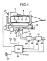
- Fig. 1 is a system view of an internal combustion engine (herein, a diesel engine 1) showing an embodiment according to the invention.
- An intake compressor of a variable-nozzle-type turbocharger 3 is disposed In an intake passage 2 of a diesel engine 1.
- An intake air is supercharged by the intake compressor, cooled in an intercooler 4, passes through an intake throttle valve 5 and through a collector 6, and flows into a combustion chamber of each cylinder.
- Fuel is pressurized by a high-pressure-fuel pump 7 and then, sent to a common rail 8 and is directly injected into the combustion chamber from a fuel injector 9 of each cylinder (common-rail-type-fuel Injection apparatus). Air flowing into the combustion chamber and fuel injected thereto are compression-ignited and an exhaust gas thereof flows into an exhaust passage 10. Part of the exhaust gas flowing into exhaust passage 10 is recirculated back to an intake side as an EGR gas through an EGR passage 11 by an EGR valve 12. The rest of the exhaust gas passes through an exhaust turbine of turbocharger 3 and drives it.
- a NOx trap catalyst 13 is disposed downstream of the exhaust turbine in exhaust passage 10 wherein the NOx of the exhaust gas flowing when an air-fuel ratio of the exhaust gas is in a lean range is trapped and the trapped Nox is purified when an air-fuel ratio of the exhaust gas is in a rich range.
- NOx trap catalyst 13 carries an oxidizing catalyst (precious metal) to oxidize exhaust components (HC, CO) flowing thereto.
- DPF 14 that traps particulate matters in the exhaust gas is disposed downstream of NOx trap catalyst 13.
- DPF 14 carries an oxidizing catalyst (precious metal) to oxidize exhaust components (HC, CO) flowing thereto.
- NOx trap catalyst 13 and DPF 14 may reversely be positioned and a DPF may carry a NOx trap catalyst being formed integrally therewith.
- a control unit (controller) 20 receives signals from an engine rotation speed sensor 21 that detects an engine rotation speed Ne, and an opening angle sensor 22 that detects an opening angle of an acceleration pedal for controlling engine 1 and also from a catalyst temperature sensor 23 that detects a temperature (catalyst temperature) of NOx trap catalyst 13, an exhaust gas pressure sensor 24 that detects an exhaust gas pressure at an inlet side of DPF 14 in exhaust passage 10, a DPF temperature sensor 25 that detects a temperature (DPF temperature) of DPF 14, and an air-fuel ratio sensor 26 that detects an air-fuel ratio (hereinafter, exhaust ⁇ shown as an air-excess rate) of the exhaust gas at an outlet side of DPF 14 in exhaust passage 10.
- exhaust ⁇ shown as an air-excess rate
- the temperature of NOx trap catalyst 13 and DPF 13 may be indirectly detected as an exhaust gas temperature with an exhaust gas temperature sensor disposed downstream thereof.
- Control unit 20 based upon these input signals, outputs a fuel injection command signal to fuel injector 9 for controlling a fuel injection amount and timing of a main injection and a post injection at a predetermined engine operating condition (during expansion stroke or exhaust stroke) after the main injection by fuel injector 9, an opening angle command signal to intake throttle valve 5, and an opening angle command signal to EGR valve 12.
- Control unit 20 performs an exhaust purification control for purifying particulate matters trapped and deposited on DPF 14 (DPF regeneration), NOx trapped and deposited on NOx trap catalyst 13 (NOx regeneration), and SOx deposited on NOx trap catalyst 13 by SOx poisoning (SOx regeneration).
- DPF regeneration purifying particulate matters trapped and deposited on DPF 14
- NOx regeneration NOx trapped and deposited on NOx trap catalyst 13
- SOx regeneration SOx deposited on NOx trap catalyst 13 by SOx poisoning
- Fig. 2 - Fig. 12 shows a flowchart of an exhaust purification control executed in control unit 20, which will be explained along with a flowchart in Fig. 2 first.
- control unit 20 When the process goes to RETURN in a flowchart in Fig. 2 - Fig. 12, all routines go back to START in a flowchart in Fig. 2.
- control unit 20 reads various sensor signals and detects an engine rotation speed Ne, an opening angle APO of the acceleration pedal, a catalyst temperature, an exhaust gas pressure in the inlet side of DPF 14, a DPF temperature, and an exhaust ⁇ in the outlet side of DPF 14 and further reads a fuel injection amount (main injection amount) Q calculated from a map having the engine rotation speed Ne and the opening angle APO of the acceleration pedal as parameters.
- control unit 20 calculates a NOx deposit amount trapped and deposited on NOx trap catalyst 13.
- the NOx deposit amount may be estimated from an integral value of an engine rotation speed or from a running distance of a vehicle. In case of use of the integral value, at a point where NOx regeneration is completed (including a point where NOx regeneration is carried out caused by SOx regeneration completion), the integral value is reset.
- a SOx deposit amount deposited on NOx trap catalyst 13 by SOx poisoning is calculated.
- the SOx deposit amount may be estimated from an integral value of the engine rotation speed or from a running distance of a vehicle. In case of use of the integral value, at a point where the SOx regeneration is completed, the integral value is reset.
- the particulate matters trapped and deposited on DPF 14 are calculated as follows. As the particulate matter deposit amount of DPF 14 increases, an exhaust gas pressure in the inlet side of DPF 14 is bound to increase. Therefore, the exhaust gas pressure in the inlet side of DPF 14 is detected by the exhaust gas pressure sensor and then, is compared with a reference exhaust gas pressure in a present engine operating condition (engine rotation speed Ne, fuel injection amount Q). As a result, the particulate matter deposit amount is estimated and may be estimated from a combination of an integral value of the engine rotation speed or a running distance after a previous DPF regeneration and the exhaust gas pressure.
- An exhaust gas pressure in the inlet side of DPF 14 is determined for each engine operating condition (Ne, Q) at a point where the particulate matter amount on the DPF 14 reaches a predetermined value PM 1 and then, that relation between the exhaust gas pressure and each engine operating condition may be described as a map shown in Fig. 13. It may be judged that it is time to regenerate the DPF 14 (PM deposit amount > PM 1) when the exhaust gas pressure therein detected by the exhaust gas pressure sensor comes to an exhaust gas pressure threshold value corresponding to a current engine operating condition (Ne, Q) in the map in Fig. 13,
- an exhaust ⁇ is controlled to be in a lean range for DPF regeneration.
- the exhaust ⁇ targeted is set corresponding to a PM deposit amount that is bound to deposit on DPF 14 based upon Fig. 14. As the PM deposit amount is larger, the exhaust ⁇ targeted is set smaller (richer side), Because as the PM deposit amount is larger, PM burning propagation during the DPF regeneration becomes more active, causing DPF 14 to be more likely to be melted.
- the control of the exhaust ⁇ is performed by use of the throttle valve and basically an intake air is controlled to be a target intake air amount shown in Fig. 15. If the exhaust ⁇ is away from the target value, the intake air is controlled further so that the exhaust ⁇ reaches the target value.
- a post injection is carried out corresponding to an engine operating condition (Ne, Q) shown in Fig. 16 or the post injection amount post Q is increased.
- reg I flag is set as 0.
- a catalyst temperature (a carrier temperature of NOx trap catalyst 13) goes beyond a predetermined value that is high enough for regenerating the SOx.
- the process goes to S 202.
- the regeneration of the SOx requires the conditions that the exhaust ⁇ is in from a stoichiometric to rich range, as well as the catalyst temperature goes beyond a predetermined value.
- T4 is set as more than 600 degrees C.
- the catalyst temperature is controlled to rise by throttling an intake air until the catalyst temperature reaches a predetermined value T4.
- T4 a predetermined value
- the exhaust ⁇ is controlled to be in a stoichiometric range for regenerating the SOx.
- an intake air is controlled by the throttle valve to be a target intake air amount for an engine operation in the exhaust ⁇ of a stoichiometric range shown in Fig. 17. If the exhaust ⁇ is away from the stoichiometric range, the intake air is controlled more so that the exhaust ⁇ reaches the stoichiometric range.
- a predetermined post injection is carried out for increasing the catalyst temperature according to Fig. 16.
- the post injection causes variations in the exhaust ⁇ , but subsequent modification of the intake air amount at S 203 enables the target exhaust ⁇ and the target catalyst temperature.
- rq-sp flag is set as 0. The reason is, when the SOx is regenerated, the NOx trap catalyst 13 is exposed to an atmosphere of the exhaust ⁇ of a stoichiometric range for a long time, Therefore, the NOx regeneration is carried out simultaneously. Accordingly, if the NOx regeneration demand is already set, the demand is withdrawn by setting rq-sp flag to 0 as the above.
- the exhaust ⁇ is controlled to be in a rich range for regenerating the NOx.
- an intake air is controlled by the throttle valve to be a target intake air amount for an engine operation in the exhaust ⁇ of a rich- spike range shown in Fig. 18. If the exhaust ⁇ is away from the target value, the intake air is controlled more so that the exhaust ⁇ reaches the target value.
- a priority making flow (1) of regeneration in Fig. 6 will be explained.
- the flow describes the regeneration priority when DPF regeneration demand and at least one of NOx regeneration demand and SOx regeneration demand are made simultaneously.
- an engine operating condition is a condition where an amount of NOx emitted from the engine is small, or a normal engine operating condition (low amount of NOx).
- a normal engine operating condition low amount of NOx
- the DPF regeneration that has an impact on an engine driveabilty is prioritized. Accordingly, the process goes to S 406.
- the NOX regeneration is prioritized for preventing deterioration of an exhaust gas emitted from the tailpipe to the outside of the vehicle. Accordingly, the process goes to s 410.
- sp flag is set as 1 for prioritizing the NOx regeneration because of a case for prioritizing the NOx regeneration.
- rq-sp flag is set as 0.
- a temperature of DPF 14 (or temperature of NOx trap catalyst 13) is required to increase more than a predetermined value for regeneration of DPF 14 (or SOx). Since an exhaust temperature of a diesel engine usually is lower than the predetermined value, the temperature of DPF 14 (or temperature of the NOx trap catalyst 13) will be increased to more than a predetermined value for the regeneration.
- the temperature increasing from the region of impossible regeneration of the SOx becomes as large as the exhaust gas emission performance deteriorates beyond an allowance value. Therefore, the regeneration is not carried out in this region.
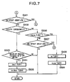
- a priority making flow (2) of regeneration in Fig.7 will be explained.
- the catalyst temperature is higher than a predetermined value (for example, activation temperature of NOx trap catalyst 13) T1 that is suitable for the SOx regeneration.
- the activation temperature T1 of NOx trap catalyst 13 is lower than the activation temperature T5 for oxidizing function of DPF 14.
- desul flag is set as 1 for prioritizing the DPF regeneration.
- sp flag is set as 1 for prioritizing the NOx regeneration because of a case for prioritizing the NOx regeneration.
- rq-sp flag is set as 0.
- the exhaust ⁇ is controlled to be less than a predetermined value , for example, ⁇ ⁇ 1.4 to control an oxygen density in the exhaust gas to less than a predetermined density so that the particulate matters left unburned or deposited do not burn for a moment and is not melted, for a temperature of DPF 14 is very high immediately after the regeneration or a high load engine operation.
- An intake air is basically controlled by the throttle valve to be a target intake air amount for preventing DPF melting shown in Fig. 15 and is feedback-controlled based upon a signal from an air-fuel ratio sensor.
- the DPF temperature goes down below a predetermined value T3 (for example, 500 degrees C) at which rapid oxidizing of the particulate matters does not start. If the DPF temperature is higher than T3, the control of the exhaust ⁇ keeps on. If the DPF temperature is lower than T3, the process goes to S 603 because DPF melting is avoidable even when the oxygen density becomes equal to an atmosphere.
- T3 for example, 500 degrees C
- the timing ("timing" a certain period of time, not a point) of the DPF regeneration takes place simultaneously with the timing of the SOx regeneration or the timing of the NOx regeneration, the DPF regeneration is carried out with a first priority and thereafter, the SOx regeneration or the NOx regeneration is carried out.
- the SOx regeneration when the timing of the SOx regeneration and the timing of the NOx regeneration take place, the SOx regeneration only is carried out and the NOx regeneration is not carried out (S210 in Fig. 4).
- the regeneration process can be efficient. Namely, since an air-fuel ratio is in from a stoichiometric to a rich range at the SOx regeneration, if the SOx regeneration is carried out, the NOx regeneration can be carried out simultaneously and carrying out the NOx regeneration separately is not needed.
- the NOx regeneration is carried out first (S 406 in Fig. 6), thereby making the regeneration process efficient.
- the oxidizing function of DPF 14 is not active, for example, immediately after an engine starts, even if an exhaust gas temperature is high, it takes time to reach a temperature condition at which the DPF regeneration can be carried out due to heat inertia. Therefore, the NOx regeneration is carried out first until the DPF reaches a temperature condition at which the DPF regeneration can be carried out. Utilizing an increase of the exhaust gas temperature due to the exhaust ⁇ being made rich for the NOx regeneration, the DPF regeneration can be carried out without deterioration of an exhaust gas emission performance,
- the NOx regeneration is carried out first (S 502 in Fig. 7), thereby making the regeneration process efficient.
- NOx trap catalyst 13 is not active, for example, immediately after an engine starts, even if an exhaust gas temperature is high, it takes time to reach a temperature condition at which the SOx regeneration can be carried out due to heat inertia. Therefore, the NOx regeneration is carried out first until the catalyst reaches a temperature condition at which the SOx regeneration can be carried out. Utilizing an increase of the exhaust gas temperature due to the exhaust ⁇ being made rich for the NOx regeneration, the SOx regeneration can be carried out without deterioration of an exhaust gas emission performance.
- the regeneration process can be carried out restraining deterioration of an exhaust gas emission performance by prioritizing the NOx regeneration.
- an oxygen density in the exhaust gas is controlled to be less than a predetermined density (S 601, S 602 in Fig. 8).
- a predetermined density S 601, S 602 in Fig. 8
- melting the DPF is properly avoided.
- the DPF temperature is very high after the DPF regeneration or the SOx regeneration is carried out and therefore, the particulate matters left unburned thereon possibly burn abnormally. Accordingly, melting the DPF is properly avoided by performing a prevention process of DPF melting such that an oxygen density in the exhaust gas is controlled to be less than a predetermined density.
- a judgment unit of regeneration timing comprises
Landscapes
- Engineering & Computer Science (AREA)
- Chemical & Material Sciences (AREA)
- Combustion & Propulsion (AREA)
- Mechanical Engineering (AREA)
- General Engineering & Computer Science (AREA)
- Biomedical Technology (AREA)
- Health & Medical Sciences (AREA)
- Environmental & Geological Engineering (AREA)
- Analytical Chemistry (AREA)
- General Chemical & Material Sciences (AREA)
- Oil, Petroleum & Natural Gas (AREA)
- Chemical Kinetics & Catalysis (AREA)
- Processes For Solid Components From Exhaust (AREA)
- Exhaust Gas After Treatment (AREA)
- Filtering Of Dispersed Particles In Gases (AREA)
Abstract
Description
Claims (8)
- An exhaust gas apparatus for purifying an exhaust gas in an internal combustion engine comprising:wherein the controller (20) separately judges timing of diesel particulate filter regeneration that purifies the particulate matter deposited on the diesel particulate filter (14), timing of SOx regeneration that purifies SOx deposited on the NOx trap catalyst (13), and timing of NOx regeneration that purifies the NOx deposited on the NOx trap catalyst (13), andan exhaust passage (10) in the internal combustion engine (1);a diesel particulate filter (14) disposed in the exhaust passage (10) to trap particulate matter in the exhaust gas flowing into the diesel particulate filter (14);a NOx trap catalyst (13) disposed in the exhaust passage (10), the NOx trap catalyst (13) trapping NOx flowing into the NOx trap catalyst (13) when an exhaust-air-fuel ratio is in a lean range and purifying the trapped NOx when the exhaust-air-fuel ratio is in a rich range; anda controller (20) that controls the internal combustion engine (1),
wherein when the diesel particulate filter (14) is active and when the timing of the diesel particulate filter regeneration takes place simultaneously with the timing of the SOx regeneration or the timing of the NOx regeneration, the controller (20) carries out the diesel particulate filter regeneration first and thereafter, the SOx regeneration or the NOx regeneration. - An exhaust gas apparatus according to claim 1, wherein the controller (20) carries out only the SOx regeneration when the timing of the SOx regeneration and the timing of the NOx regeneration take place simultaneously.
- An exhaust gas apparatus according to claim 1 or 2, wherein the diesel particulate filter (14) oxidizes an exhaust component flowing thereto, and
wherein when oxidization of the diesel particulate filter (14) is not active and the controller (20) detects that the timing of the diesel particulate filter (14) and the timing of the NOx regeneration take place simultaneously, the controller (20) carries out the NOx regeneration prior to the diesel particulate filter (14) regeneration. - An exhaust gas apparatus according to any of claim 1 - 3, wherein when the NOx trap catalyst (13) is not active and when controller (20) detects that the timing of the SOx and the timing of the NOx regeneration take place simultaneously, the controller (20) carries out the NOx regeneration prior to the SOx regeneration.
- An exhaust gas apparatus for purifying an exhaust gas in an internal combustion engine comprising:wherein the controller (20) separately judges timing of diesel particulate filter regeneration that purifies the particulate matter deposited on the diesel particulate filter (14), timing of SOx regeneration that purifies SOx deposited on the NOX trap catalyst (13), and timing of NOx regeneration that purifies NOx deposited on the NOx trap catalyst (13), andan exhaust passage (10) in the internal combustion engine (1);a diesel particulate filter (14) disposed in the exhaust passage (10) to trap particulate matter in the exhaust gas flowing into the diesel particulate filter (14);a NOx trap catalyst (13) disposed in the exhaust passage (10), the NOx trap catalyst (13) trapping NOx flowing into the NOx trap catalyst (13) when an exhaust-air-fuel ratio is in a lean range and purifying the trapped NOx when the exhaust-air-fuel ratio is in a rich range; anda controller (20) that controls the internal combustion engine (1),
wherein when the timing of the diesel particulate filter (14) regeneration takes place simultaneously with the timing of the SOx regeneration or the timing of the NOx regeneration, the controller (20) carries out the NOx regeneration first when an amount of the NOx emitted from the internal combustion engine (1) is larger than a predetermined value. - An exhaust gas apparatus according to any of claim 1- 5, wherein the controller (20) controls an oxygen density in the exhaust gas to be below a predetermined value when a temperature of the diesel particulate filter (14) goes beyond a predetermined value after the controller (20) carries out the diesel particulate filter (14) regeneration or the SOx regeneration.
- An exhaust gas apparatus according to any of claim 1 - 6, wherein the controller (20) comprises:a judgment unit of regeneration timing that comprisesa first judgment unit that judges the diesel particulate filter regeneration demand based upon a particulate matter amount on the diesel particulate filter;a second judgment unit that judges the SOx regeneration demand based upon a SOx deposit amount on the NOx trap catalyst;a third judgment unit that judges whether or not it is possible to carry out a SOx regeneration based upon an engine operating condition;a fourth judgment unit that judges whether or not it is possible to carry out the diesel particulate filter regeneration based upon the engine operating condition;a fifth judgment unit that judges it is time to regenerate the diesel particulate filter (14) based upon judgment results of the first judgment unit and the fourth judgment unit; anda sixth judgment unit that judges it is time to regenerate the SOx based upon judgment results of the second judgment unit and the third judgment unit.
- A method for purifying an exhaust gas in an internal combustion engine comprising:providing an exhaust passage (10) in the internal combustion engine (1);providing a diesel particulate filter (14) in the exhaust passage (10);trapping particulate matter in the exhaust gas flowing into the diesel particulate filter (14);providing a NOx trap catalyst (13) in the exhaust passage (10);trapping NOx flowing into the NOx trap catalyst (13) by the NOx trap catalyst (13) when an exhaust-air-fuel ratio is in a lean range;purifying the trapped NOx when the exhaust -air-fuel ratio is in a rich range;separately judging timing of a diesel particulate filter regeneration that purifies the particulate matter deposited on the diesel particulate filter (14), timing of SOx regeneration that purifies SOx deposited on the NOx trap catalyst (13), and timing of NOx regeneration that purifies NOx deposited on the NOx trap catalyst (13); andcarrying out the diesel particulate filter regeneration with a first priority and thereafter, the SOx regeneration or the NOx regeneration when the timing of the diesel particulate filter regeneration take place simultaneously with the timing of the SOx regeneration or the timing of the NOx regeneration.
Applications Claiming Priority (2)
| Application Number | Priority Date | Filing Date | Title |
|---|---|---|---|
| JP2002145366 | 2002-05-20 | ||
| JP2002145366A JP4175022B2 (en) | 2002-05-20 | 2002-05-20 | Exhaust gas purification device for internal combustion engine |
Publications (3)
| Publication Number | Publication Date |
|---|---|
| EP1365117A2 true EP1365117A2 (en) | 2003-11-26 |
| EP1365117A3 EP1365117A3 (en) | 2003-12-03 |
| EP1365117B1 EP1365117B1 (en) | 2005-11-02 |
Family
ID=29397750
Family Applications (1)
| Application Number | Title | Priority Date | Filing Date |
|---|---|---|---|
| EP03011434A Expired - Lifetime EP1365117B1 (en) | 2002-05-20 | 2003-05-20 | Exhaust gas apparatus and method for purifiying exhaust gas in internal combustion engine |
Country Status (4)
| Country | Link |
|---|---|
| US (1) | US6962045B2 (en) |
| EP (1) | EP1365117B1 (en) |
| JP (1) | JP4175022B2 (en) |
| DE (1) | DE60302098T2 (en) |
Cited By (9)
| Publication number | Priority date | Publication date | Assignee | Title |
|---|---|---|---|---|
| WO2006006031A1 (en) * | 2004-07-05 | 2006-01-19 | Toyota Jidosha Kabushiki Kaisha | Control method and control device for exhaust gas control apparatus |
| US7225613B2 (en) | 2005-01-26 | 2007-06-05 | Ford Global Technologies, Llc | Diesel engine after treatment device for conversion of nitrogen oxide and particulate matter |
| FR2897104A1 (en) * | 2006-02-09 | 2007-08-10 | Peugeot Citroen Automobiles Sa | SYSTEM AND METHOD FOR SOX REMOVAL (SULFUR OXIDE), SUPERVISOR FOR THIS SYSTEM |
| WO2008066482A1 (en) * | 2006-11-29 | 2008-06-05 | Scania Cv Ab (Publ) | Arrangement and method for a supercharged combustion engine |
| EP2063077A4 (en) * | 2007-04-03 | 2010-11-03 | Toyota Motor Co Ltd | EXHAUST GAS PURIFYING DEVICE FOR INTERNAL COMBUSTION ENGINE |
| US8037675B2 (en) | 2006-06-19 | 2011-10-18 | Toyota Jidosha Kabushiki Kaisha | Exhaust gas purification system for internal combustion engine and method for exhaust gas purification |
| GB2490934A (en) * | 2011-05-19 | 2012-11-21 | Gm Global Tech Operations Inc | Method of desulphurisation of a Lean NOx Trap |
| CN107429586A (en) * | 2015-03-11 | 2017-12-01 | 五十铃自动车株式会社 | Exhaust purification system and control method for exhaust purification system |
| WO2018134151A1 (en) * | 2017-01-18 | 2018-07-26 | Volkswagen Ag | Regeneration of a particulate filter or four-way catalytic converter in an exhaust system of an internal combustion engine |
Families Citing this family (46)
| Publication number | Priority date | Publication date | Assignee | Title |
|---|---|---|---|---|
| JP3791470B2 (en) * | 2002-07-02 | 2006-06-28 | トヨタ自動車株式会社 | Exhaust gas purification device for internal combustion engine |
| JP4241032B2 (en) * | 2002-12-26 | 2009-03-18 | 日産自動車株式会社 | Sulfur poisoning release control device for diesel engine catalyst |
| US6863058B2 (en) * | 2003-02-03 | 2005-03-08 | Ford Global Technologies, Llc | System and method for reducing NOx emissions during transient conditions in a diesel fueled vehicle |
| JP2004339993A (en) * | 2003-05-14 | 2004-12-02 | Toyota Motor Corp | Exhaust gas purification system for internal combustion engine |
| FR2856432B1 (en) * | 2003-06-23 | 2005-09-30 | Renault Sa | METHOD FOR CONTROLLING A DIESEL ENGINE MOTORIZATION SYSTEM AND NITROGEN OXIDE TRAP |
| JP2005048751A (en) * | 2003-07-31 | 2005-02-24 | Nissan Motor Co Ltd | Engine control device |
| US7192463B2 (en) * | 2003-07-11 | 2007-03-20 | Cummins Filtration Ip, Inc. | Arrangement for mounting electrical components to an aftertreatment filter |
| JP4304447B2 (en) * | 2003-08-29 | 2009-07-29 | いすゞ自動車株式会社 | Exhaust gas purification method and exhaust gas purification system |
| JP2005155374A (en) * | 2003-11-21 | 2005-06-16 | Isuzu Motors Ltd | Exhaust purification method and exhaust purification system |
| FR2862708B1 (en) | 2003-11-24 | 2008-01-18 | Inst Francais Du Petrole | METHOD AND DEVICE FOR DESULFATATION OF A NITRIC OXIDE TRAP AND REGENERATION OF A PARTICLE FILTER |
| FR2862703B1 (en) * | 2003-11-25 | 2006-02-24 | Peugeot Citroen Automobiles Sa | A NOX TRAP DESULFATATION SYSTEM FOR MOTOR VEHICLE ENGINE |
| US7155331B1 (en) | 2003-12-15 | 2006-12-26 | Donaldson Company, Inc. | Method of prediction of NOx mass flow in exhaust |
| JP4413020B2 (en) | 2004-01-21 | 2010-02-10 | ヤンマー株式会社 | Exhaust gas purification device and control method thereof |
| FR2866927B1 (en) * | 2004-02-27 | 2008-03-07 | Peugeot Citroen Automobiles Sa | SYSTEM FOR AIDING THE REGENERATION OF MEANS OF DEPOLLUTION |
| JP4523317B2 (en) * | 2004-04-09 | 2010-08-11 | 本田技研工業株式会社 | Diesel engine exhaust purification system |
| WO2006010277A2 (en) * | 2004-07-29 | 2006-02-02 | Nxtgen Emission Controls Inc. | Integrated system for reducing fuel consumption and emissions in an internal combustion engine |
| US7197867B2 (en) * | 2004-10-04 | 2007-04-03 | Southwest Research Institute | Method for the simultaneous desulfation of a lean NOx trap and regeneration of a Diesel particulate filter |
| US7441403B2 (en) * | 2004-12-20 | 2008-10-28 | Detroit Diesel Corporation | Method and system for determining temperature set points in systems having particulate filters with regeneration capabilities |
| US7210286B2 (en) * | 2004-12-20 | 2007-05-01 | Detroit Diesel Corporation | Method and system for controlling fuel included within exhaust gases to facilitate regeneration of a particulate filter |
| US7461504B2 (en) * | 2004-12-21 | 2008-12-09 | Detroit Diesel Corporation | Method and system for controlling temperatures of exhaust gases emitted from internal combustion engine to facilitate regeneration of a particulate filter |
| US7434388B2 (en) | 2004-12-22 | 2008-10-14 | Detroit Diesel Corporation | Method and system for regeneration of a particulate filter |
| US20060130465A1 (en) * | 2004-12-22 | 2006-06-22 | Detroit Diesel Corporation | Method and system for controlling exhaust gases emitted from an internal combustion engine |
| US7076945B2 (en) * | 2004-12-22 | 2006-07-18 | Detroit Diesel Corporation | Method and system for controlling temperatures of exhaust gases emitted from an internal combustion engine to facilitate regeneration of a particulate filter |
| JP4367335B2 (en) | 2004-12-27 | 2009-11-18 | 日産自動車株式会社 | Engine control device. |
| JP2006183599A (en) * | 2004-12-28 | 2006-07-13 | Nissan Motor Co Ltd | Exhaust gas purification device for internal combustion engine |
| US7406822B2 (en) * | 2005-06-30 | 2008-08-05 | Caterpillar Inc. | Particulate trap regeneration system and control strategy |
| EP1745836A1 (en) | 2005-07-21 | 2007-01-24 | Ford Global Technologies, LLC | A method and an arrangement for purifying exhaust gas in an internal combustion engine |
| JP4107320B2 (en) * | 2005-10-17 | 2008-06-25 | トヨタ自動車株式会社 | Exhaust gas purification device for internal combustion engine |
| JP4832068B2 (en) * | 2005-12-05 | 2011-12-07 | トヨタ自動車株式会社 | Air-fuel ratio control device |
| FR2897103B1 (en) * | 2006-02-09 | 2011-06-10 | Peugeot Citroen Automobiles Sa | SYSTEM AND METHOD FOR SOX REMOVAL (SULFUR OXIDE), STOP MODULE FOR THIS SYSTEM |
| US7963832B2 (en) * | 2006-02-22 | 2011-06-21 | Cummins Inc. | Engine intake air temperature management system |
| US7654079B2 (en) * | 2006-11-07 | 2010-02-02 | Cummins, Inc. | Diesel oxidation catalyst filter heating system |
| US7654076B2 (en) * | 2006-11-07 | 2010-02-02 | Cummins, Inc. | System for controlling absorber regeneration |
| US7707826B2 (en) | 2006-11-07 | 2010-05-04 | Cummins, Inc. | System for controlling triggering of adsorber regeneration |
| US7533523B2 (en) * | 2006-11-07 | 2009-05-19 | Cummins, Inc. | Optimized desulfation trigger control for an adsorber |
| US7594392B2 (en) * | 2006-11-07 | 2009-09-29 | Cummins, Inc. | System for controlling adsorber regeneration |
| US8256210B2 (en) * | 2006-12-21 | 2012-09-04 | Cummins Inc. | Flexible fuel injection for multiple modes of diesel engine exhaust aftertreatment |
| JP4355003B2 (en) * | 2007-03-08 | 2009-10-28 | 本田技研工業株式会社 | Control device for internal combustion engine |
| US8011179B2 (en) * | 2007-05-31 | 2011-09-06 | Caterpillar Inc. | Method and system for maintaining aftertreatment efficiency |
| US8096111B2 (en) * | 2007-06-22 | 2012-01-17 | Ford Global Technologies, Llc | Reduction of NOx trap at engine shutoff |
| JP4430705B2 (en) * | 2007-10-02 | 2010-03-10 | 本田技研工業株式会社 | Exhaust gas purification device for internal combustion engine |
| US20090133387A1 (en) | 2007-11-22 | 2009-05-28 | Nissan Motor Co., Ltd. | Particulate matter trap filter regeneration temperature control for internal combustion engine |
| JP5257024B2 (en) * | 2008-11-27 | 2013-08-07 | 日産自動車株式会社 | Exhaust gas purification device for internal combustion engine |
| US20110146245A1 (en) * | 2009-12-22 | 2011-06-23 | Caterpillar Inc. | Sulfur detection routine |
| US8413432B2 (en) * | 2010-06-30 | 2013-04-09 | GM Global Technology Operations LLC | Particulate filter regeneration interruption systems and methods |
| US11002205B2 (en) | 2019-07-22 | 2021-05-11 | Caterpillar Inc. | Regeneration control system for oxidation catalyst regeneration in internal combustion engine |
Family Cites Families (15)
| Publication number | Priority date | Publication date | Assignee | Title |
|---|---|---|---|---|
| JP2600492B2 (en) | 1991-10-03 | 1997-04-16 | トヨタ自動車株式会社 | Exhaust gas purification device for internal combustion engine |
| CA2097609C (en) | 1991-10-03 | 1999-03-16 | Shinichi Takeshima | Device for purifying exhaust of internal combustion engine |
| JP2722987B2 (en) | 1992-09-28 | 1998-03-09 | トヨタ自動車株式会社 | Exhaust gas purification device for internal combustion engine |
| JP3899534B2 (en) * | 1995-08-14 | 2007-03-28 | トヨタ自動車株式会社 | Exhaust gas purification method for diesel engine |
| JP3645704B2 (en) * | 1997-03-04 | 2005-05-11 | トヨタ自動車株式会社 | Exhaust gas purification device for internal combustion engine |
| JP3228232B2 (en) * | 1998-07-28 | 2001-11-12 | トヨタ自動車株式会社 | Exhaust gas purification device for internal combustion engine |
| ATE224004T1 (en) | 1998-08-07 | 2002-09-15 | Volkswagen Ag | METHOD AND DEVICE FOR DE-SULFATATION OF A CATALYST DEVICE |
| DE19850757A1 (en) * | 1998-08-07 | 2000-02-17 | Volkswagen Ag | Method and device for desulfating a catalyst device |
| US6189316B1 (en) * | 1999-05-19 | 2001-02-20 | Ford Global Technologies, Inc. | Emission device temperature control system |
| US6615580B1 (en) * | 1999-06-23 | 2003-09-09 | Southwest Research Institute | Integrated system for controlling diesel engine emissions |
| DE19945336A1 (en) | 1999-09-22 | 2001-03-29 | Volkswagen Ag | Method for controlling regeneration of a particle filter and desulfurization of a NOx storage catalytic converter |
| JP3558017B2 (en) | 2000-07-21 | 2004-08-25 | トヨタ自動車株式会社 | Exhaust gas purification device for internal combustion engine |
| US6758036B1 (en) * | 2000-10-27 | 2004-07-06 | Delphi Technologies, Inc. | Method for sulfur protection of NOx adsorber |
| DE50000400D1 (en) * | 2000-11-03 | 2002-09-26 | Ford Global Tech Inc | Control arrangement and method for interrupting the regeneration of a particle filter of a diesel engine |
| WO2003031780A1 (en) * | 2001-10-11 | 2003-04-17 | Southwest Research Institute | Systems and method for controlling diesel engine emissions |
-
2002
- 2002-05-20 JP JP2002145366A patent/JP4175022B2/en not_active Expired - Lifetime
-
2003
- 2003-05-20 DE DE60302098T patent/DE60302098T2/en not_active Expired - Lifetime
- 2003-05-20 EP EP03011434A patent/EP1365117B1/en not_active Expired - Lifetime
- 2003-05-20 US US10/441,114 patent/US6962045B2/en not_active Expired - Lifetime
Cited By (14)
| Publication number | Priority date | Publication date | Assignee | Title |
|---|---|---|---|---|
| WO2006006031A1 (en) * | 2004-07-05 | 2006-01-19 | Toyota Jidosha Kabushiki Kaisha | Control method and control device for exhaust gas control apparatus |
| US7225613B2 (en) | 2005-01-26 | 2007-06-05 | Ford Global Technologies, Llc | Diesel engine after treatment device for conversion of nitrogen oxide and particulate matter |
| FR2897104A1 (en) * | 2006-02-09 | 2007-08-10 | Peugeot Citroen Automobiles Sa | SYSTEM AND METHOD FOR SOX REMOVAL (SULFUR OXIDE), SUPERVISOR FOR THIS SYSTEM |
| WO2007090975A3 (en) * | 2006-02-09 | 2007-10-25 | Peugeot Citroen Automobiles Sa | SYSTEM AND METHOD FOR THE ELIMINATION OF SOx (SULPHUR OXIDE), SUPERVISOR FOR SAID SYSTEM |
| US8037675B2 (en) | 2006-06-19 | 2011-10-18 | Toyota Jidosha Kabushiki Kaisha | Exhaust gas purification system for internal combustion engine and method for exhaust gas purification |
| WO2008066482A1 (en) * | 2006-11-29 | 2008-06-05 | Scania Cv Ab (Publ) | Arrangement and method for a supercharged combustion engine |
| EP2063077A4 (en) * | 2007-04-03 | 2010-11-03 | Toyota Motor Co Ltd | EXHAUST GAS PURIFYING DEVICE FOR INTERNAL COMBUSTION ENGINE |
| US8156731B2 (en) | 2007-04-03 | 2012-04-17 | Toyota Jidosha Kabushiki Kaisha | Exhaust purification device of internal combustion engine |
| GB2490934A (en) * | 2011-05-19 | 2012-11-21 | Gm Global Tech Operations Inc | Method of desulphurisation of a Lean NOx Trap |
| CN107429586A (en) * | 2015-03-11 | 2017-12-01 | 五十铃自动车株式会社 | Exhaust purification system and control method for exhaust purification system |
| EP3269954A4 (en) * | 2015-03-11 | 2018-08-29 | Isuzu Motors Limited | Exhaust purification system, and control method for exhaust purification system |
| US10392986B2 (en) | 2015-03-11 | 2019-08-27 | Isuzu Motors Limited | Exhaust purification system, and control method for exhaust purification system |
| CN107429586B (en) * | 2015-03-11 | 2020-09-15 | 五十铃自动车株式会社 | Exhaust gas purification system and control method of exhaust gas purification system |
| WO2018134151A1 (en) * | 2017-01-18 | 2018-07-26 | Volkswagen Ag | Regeneration of a particulate filter or four-way catalytic converter in an exhaust system of an internal combustion engine |
Also Published As
| Publication number | Publication date |
|---|---|
| JP2003336520A (en) | 2003-11-28 |
| JP4175022B2 (en) | 2008-11-05 |
| EP1365117A3 (en) | 2003-12-03 |
| US20030213235A1 (en) | 2003-11-20 |
| EP1365117B1 (en) | 2005-11-02 |
| DE60302098D1 (en) | 2005-12-08 |
| DE60302098T2 (en) | 2006-06-01 |
| US6962045B2 (en) | 2005-11-08 |
Similar Documents
| Publication | Publication Date | Title |
|---|---|---|
| EP1365117B1 (en) | Exhaust gas apparatus and method for purifiying exhaust gas in internal combustion engine | |
| US7610753B2 (en) | Exhaust gas purification apparatus for internal combustion engine and method thereof | |
| EP1419309B1 (en) | Exhaust gas purification system and method for internal combustion engine | |
| US7100365B2 (en) | Combustion control system of internal combustion engine | |
| US7054734B2 (en) | Combustion control system of internal combustion engine | |
| JP4052178B2 (en) | Exhaust gas purification device for internal combustion engine | |
| US7062907B2 (en) | Regeneration control system | |
| JP2006183599A (en) | Exhaust gas purification device for internal combustion engine | |
| KR100689921B1 (en) | Engine combustion control | |
| US6907862B2 (en) | Combustion control apparatus for internal combustion engine | |
| US7334398B2 (en) | Combustion control apparatus and method for internal combustion engine | |
| JP2003120369A (en) | Exhaust gas purification device for internal combustion engine | |
| JP4061999B2 (en) | Exhaust gas purification device for internal combustion engine | |
| US7594390B2 (en) | Combustion control apparatus and method for internal combustion engine | |
| EP1725748A1 (en) | Exhaust purifying apparatus and exhaust purifying method for internal combustion engine | |
| EP1725751B1 (en) | Regeneration controller for exhaust purification apparatus of internal combustion engine | |
| JP2004028030A (en) | Exhaust gas purification device for internal combustion engine | |
| JP4735505B2 (en) | Surge prevention control device and surge prevention control method for turbocharged engine | |
| JP6569873B2 (en) | Engine exhaust purification system | |
| JP2004036552A (en) | Exhaust gas purification device for internal combustion engine | |
| JP2005042715A (en) | Combustion control device for internal combustion engine | |
| JP2003201885A (en) | Exhaust purification device for internal combustion engine |
Legal Events
| Date | Code | Title | Description |
|---|---|---|---|
| PUAI | Public reference made under article 153(3) epc to a published international application that has entered the european phase |
Free format text: ORIGINAL CODE: 0009012 |
|
| PUAL | Search report despatched |
Free format text: ORIGINAL CODE: 0009013 |
|
| 17P | Request for examination filed |
Effective date: 20030520 |
|
| AK | Designated contracting states |
Kind code of ref document: A2 Designated state(s): AT BE BG CH CY CZ DE DK EE ES FI FR GB GR HU IE IT LI LU MC NL PT RO SE SI SK TR |
|
| AX | Request for extension of the european patent |
Extension state: AL LT LV MK |
|
| AK | Designated contracting states |
Kind code of ref document: A3 Designated state(s): AT BE BG CH CY CZ DE DK EE ES FI FR GB GR HU IE IT LI LU MC NL PT RO SE SI SK TR |
|
| AX | Request for extension of the european patent |
Extension state: AL LT LV MK |
|
| RIC1 | Information provided on ipc code assigned before grant |
Ipc: 7F 01N 9/00 B Ipc: 7F 01N 3/023 A Ipc: 7F 01N 3/08 B Ipc: 7F 01N 7/02 B |
|
| 17Q | First examination report despatched |
Effective date: 20040528 |
|
| AKX | Designation fees paid |
Designated state(s): DE FR GB |
|
| GRAP | Despatch of communication of intention to grant a patent |
Free format text: ORIGINAL CODE: EPIDOSNIGR1 |
|
| GRAS | Grant fee paid |
Free format text: ORIGINAL CODE: EPIDOSNIGR3 |
|
| GRAA | (expected) grant |
Free format text: ORIGINAL CODE: 0009210 |
|
| AK | Designated contracting states |
Kind code of ref document: B1 Designated state(s): DE FR GB |
|
| REG | Reference to a national code |
Ref country code: GB Ref legal event code: FG4D |
|
| REF | Corresponds to: |
Ref document number: 60302098 Country of ref document: DE Date of ref document: 20051208 Kind code of ref document: P |
|
| ET | Fr: translation filed | ||
| PLBE | No opposition filed within time limit |
Free format text: ORIGINAL CODE: 0009261 |
|
| STAA | Information on the status of an ep patent application or granted ep patent |
Free format text: STATUS: NO OPPOSITION FILED WITHIN TIME LIMIT |
|
| 26N | No opposition filed |
Effective date: 20060803 |
|
| REG | Reference to a national code |
Ref country code: FR Ref legal event code: PLFP Year of fee payment: 14 |
|
| REG | Reference to a national code |
Ref country code: FR Ref legal event code: PLFP Year of fee payment: 15 |
|
| REG | Reference to a national code |
Ref country code: FR Ref legal event code: PLFP Year of fee payment: 16 |
|
| PGFP | Annual fee paid to national office [announced via postgrant information from national office to epo] |
Ref country code: GB Payment date: 20220401 Year of fee payment: 20 Ref country code: FR Payment date: 20220408 Year of fee payment: 20 Ref country code: DE Payment date: 20220329 Year of fee payment: 20 |
|
| REG | Reference to a national code |
Ref country code: DE Ref legal event code: R071 Ref document number: 60302098 Country of ref document: DE |
|
| REG | Reference to a national code |
Ref country code: GB Ref legal event code: PE20 Expiry date: 20230519 |
|
| PG25 | Lapsed in a contracting state [announced via postgrant information from national office to epo] |
Ref country code: GB Free format text: LAPSE BECAUSE OF EXPIRATION OF PROTECTION Effective date: 20230519 |