EP1365051A2 - Three-dimensional woven fabric manufacturing method and apparatus - Google Patents
Three-dimensional woven fabric manufacturing method and apparatus Download PDFInfo
- Publication number
- EP1365051A2 EP1365051A2 EP03010603A EP03010603A EP1365051A2 EP 1365051 A2 EP1365051 A2 EP 1365051A2 EP 03010603 A EP03010603 A EP 03010603A EP 03010603 A EP03010603 A EP 03010603A EP 1365051 A2 EP1365051 A2 EP 1365051A2
- Authority
- EP
- European Patent Office
- Prior art keywords
- yarn
- vertical
- yarns
- stitching
- laminate
- Prior art date
- Legal status (The legal status is an assumption and is not a legal conclusion. Google has not performed a legal analysis and makes no representation as to the accuracy of the status listed.)
- Withdrawn
Links
- 239000002759 woven fabric Substances 0.000 title claims abstract description 38
- 238000004519 manufacturing process Methods 0.000 title claims abstract description 25
- 238000010030 laminating Methods 0.000 claims abstract description 13
- 238000009941 weaving Methods 0.000 description 6
- 239000000835 fiber Substances 0.000 description 3
- 238000010009 beating Methods 0.000 description 2
- 239000004744 fabric Substances 0.000 description 2
- 238000000034 method Methods 0.000 description 2
- OKTJSMMVPCPJKN-UHFFFAOYSA-N Carbon Chemical compound [C] OKTJSMMVPCPJKN-UHFFFAOYSA-N 0.000 description 1
- 229910052799 carbon Inorganic materials 0.000 description 1
- 239000000919 ceramic Substances 0.000 description 1
- 238000001514 detection method Methods 0.000 description 1
- 238000003780 insertion Methods 0.000 description 1
- 230000037431 insertion Effects 0.000 description 1
- 125000006850 spacer group Chemical group 0.000 description 1
Images


Classifications
-
- D—TEXTILES; PAPER
- D03—WEAVING
- D03D—WOVEN FABRICS; METHODS OF WEAVING; LOOMS
- D03D41/00—Looms not otherwise provided for, e.g. for weaving chenille yarn; Details peculiar to these looms
-
- D—TEXTILES; PAPER
- D03—WEAVING
- D03D—WOVEN FABRICS; METHODS OF WEAVING; LOOMS
- D03D13/00—Woven fabrics characterised by the special disposition of the warp or weft threads, e.g. with curved weft threads, with discontinuous warp threads, with diagonal warp or weft
- D03D13/002—With diagonal warps or wefts
-
- D—TEXTILES; PAPER
- D03—WEAVING
- D03D—WOVEN FABRICS; METHODS OF WEAVING; LOOMS
- D03D25/00—Woven fabrics not otherwise provided for
- D03D25/005—Three-dimensional woven fabrics
-
- D—TEXTILES; PAPER
- D03—WEAVING
- D03D—WOVEN FABRICS; METHODS OF WEAVING; LOOMS
- D03D41/00—Looms not otherwise provided for, e.g. for weaving chenille yarn; Details peculiar to these looms
- D03D41/004—Looms for three-dimensional fabrics
Definitions
- the present invention relates to a three-dimensional woven fabric manufacturing method and apparatus for manufacturing a multiaxis three-dimensional woven fiber structure (a multiaxis three-dimensional woven fabric), and in particular, to a three-dimensional woven fabric manufacturing method and apparatus adapted to increase the density of a weave in a three-dimensional woven fabric.
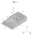
- a 5-axis three-dimensional woven fabric W has hitherto been developed and provided which is composed of warps X, wefts Y, a set of bias yarns B1, B2, and vertical yarns Z as shown in Figure 1.
- a three-dimensional weaving machine that weaves this 5-axis three-dimensional woven fabric W has been described and proposed in, for example, the Unexamined Japanese Patent Application Publication (Tokkai Hei) No. 10-325041. With the three-dimensional weaving machine described in this publication, the warps X and the set of bias yarns B1, B2 are first guided to a cloth fell of the weaving machine. Then, the warps X are used to form a plurality of warp layers.
- the bias yarns B1, B2 are used to form a set of two bias yarn layers. Each of the bias yarn layers is arranged between the warp layers.
- the bias yarns in one of the two bias yarn layers of the set are inclined from the warps at a specified angle, while the bias yarns in the other bias yarn layer are inclined in the opposite direction at the same angle.
- the wefts Y are inlaid between the warp layers and between the bias layer.
- the vertical yarns Z are inlaid between the warps of each warp layer and between the bias yarns of each bias yarn layer.
- a vertical yarn inlaying member for inlaying the vertical yarns Z is controlled by means that moves up and down between the warps. Further, a beating operation is performed while threading the vertical yarns between fabric layers.
- the vertical yarns are supplied and beaten by the vertical yarn inlaying member, also acting as a yarn guide. Accordingly, a gap is required through which the yarn guide can pass. This disadvantageously limits the dense arrangement of fibers. This in turn limits an increase in the density of a weave as a three-dimensional woven fabric product.
- the present invention provides a three-dimensional woven fabric manufacturing method comprising a step of forming a 4-axis yarn laminate of a desired thickness by using warps, wefts, and a set of bias yarns to laminate a plurality of warp layers, a plurality of weft layers, and a plurality of layers of a set of bias yarns each, and a vertical yarn stitching step of stitching vertical yarns into the 4-axis yarn laminate from one surface of the 4-axis yarn laminate in its laminating direction, and in that a three-dimensional woven fabric is formed by stitching the vertical yarns to fasten the warps, wefts, and set of bias yarns together.
- the present invention provides a three-dimensional woven fabric manufacturing apparatus comprising 4-axis yarn laminate forming means for forming a 4-axis yarn laminate by operating, in order to form warp layers, weft layers, and layers of a set of bias yarns each on a frame comprising yarn guard switching means around an outer periphery of the frame, to route a plurality of yarns supplied by a yarn supplying source in a direction in which the warp layers are formed, in a direction in which the weft layers are formed, and in a direction in which the layers of a set of bias yarns each are formed, respectively, to distributively direct said plurality of yarns, and vertical yarn stitching means for stitching vertical yarns into the 4-axis yarn laminate from one surface of the 4-axis yarn laminate in its laminating direction to allow the vertical yarns to fasten the warps, wefts, and set of bias yarns together.
- the present invention provides the three-dimensional woven fabric manufacturing apparatus wherein the yarn guard switching means comprises a large number of yarn guard pins attached to the outer periphery of the frame so as to extend in a lateral direction.
- the present invention provides the three-dimensional woven fabric manufacturing apparatus wherein the vertical yarn stitching means comprises a stitching head provided with a plurality of vertical yarn stitching needles and vertical yarn feeding means, and a needle guide plate that guides the plurality of vertical yarn stitching needles, and the apparatus further comprises controlled driving means for driving the vertical stitching means and the needle guide plate in a controlled manner so that when the vertical yarn stitching means lowers, the needle guide plate lowers before the vertical yarn stitching means to press the 4-axis yarn laminate and so that when the vertical yarn stitching means elevates, the needle guide plate leaves said 4-axis yarn laminate after the vertical yarn stitching means.
- the present invention provides the three-dimensional woven fabric manufacturing apparatus wherein the vertical yarn stitching means comprise fastening yarn inlaying means for inlaying a fastening yarn at the other surface of the 4-axis yarn laminate in its laminating direction so that the fastening yarn intertwines with said vertical yarns, every time the vertical yarns are stitched.
- the vertical yarn stitching means comprise fastening yarn inlaying means for inlaying a fastening yarn at the other surface of the 4-axis yarn laminate in its laminating direction so that the fastening yarn intertwines with said vertical yarns, every time the vertical yarns are stitched.
- the present invention provides the three-dimensional woven fabric manufacturing apparatus wherein the plurality of vertical yarn stitching needles of the vertical yarn stitching means each comprises a through-hole that penetrates the vertical yarn stitching needle in its axial direction so that the vertical yarn Z is inlaid and guided through the through-hole.
- the three-dimensional woven fabric manufacturing method comprises a step of forming a 4-axis laminate LB of a desired thickness by using the warps X, the wefts Y and the set of bias yarns B1, B2 to laminate a plurality of warp layers, a plurality of weft layers, and a plurality of layers of a set of bias yarns B1, B2, and a vertical yarn stitching step of stitching the vertical yarns Z into the 4-axis laminate LB from one surface LBa of it in its laminating direction.
- a three-dimensional woven fabric W is woven by thus stitching the vertical yarns to fasten the warps X, wefts Y, and set of bias yarns B1, B2 together.
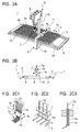
- the above 4-axis laminate LB is formed by 4-axis yarn laminate forming means 1 such as the one shown in Figure 2.
- a frame 2 is provided to form the 4-axis yarn laminate LB.
- the frame 2 is composed of a shaft member 3 having a rectangular horizontal cross section and is shaped like a rectangle of external size L1 ⁇ L2.
- Yarn guard pins 4 are provided around the outer periphery of the frame 2 at predetermined pitch intervals as yarn guard switching means.
- the yarn guard pins 4 are utilized to form the following layers on the frame: warp layers each comprising a plurality of yarns extending in the warp direction, weft layers each comprising a plurality of yarns extending in the weft direction, + ⁇ -degree bias yarn layers each comprising a plurality of yarns extending in a + ⁇ -degree bias yarn direction, and - ⁇ -degree bias yarn layers each comprising a plurality of yarns extending in a - ⁇ -degree bias yarn direction.
- the 4-axis yarn laminate forming means 1 includes a machine body 8 provided with a yarn supplying source composed of a plurality of bobbins 5 and a yarn distribution guide member 7 that guides a plurality of yarns (warps X, wefts Y, and shared yarns Cy as bias yarns B1, B2) supplied by the yarn supplying source 6.
- the 4-axis yarn laminate forming means 1 further includes an X-axis direction reciprocatory driving mechanism 9 on which the frame 2 is mounted and reciprocated in the direction of an arrow Yx.
- the machine body 8 comprises a machine base 10 and a Y-axis direction reciprocatory driving mechanism 12 for reciprocation along an upper rail 11 of the machine base 10 in the direction of an arrow Yx.
- a strut member 13 reciprocated by the Y-axis direction reciprocatory driving mechanism 12 along the upper rail 11 of the machine base 10 in the direction of an arrow Yy is provided with the yarn supplying source 6, composed of the plurality of bobbins 5, and the yarn distribution guide member 7, which guides a plurality of yarns supplied by the yarn supplying source 6.
- the yarn distribution guide member 7 has a plurality of guide holes 14 formed in a line and through which yarns are inserted and guided.
- the yarn distribution guide member 7 is adapted to move up and down in the direction of an arrow Ya with respect to the strut member 13.
- the yarn distribution guide member 7 is further adapted to be freely rotationally moved along the direction of an arrow Yb and fixed so that the row of the guide holes 14, arranged in a line, is placed at a 0-degree angular position, shown in Figure 2A, and a 90-degree angular position. It is also adapted to pivot freely along an arrow Yc around a shaft 15 as shown in Figure 2B.
- the plurality of guide holes 14 are formed by a pipe-like yarn inserting member Pa of appropriate length dimensions as shown in Figures 2C2 and 2C3.
- the row of the guide holes 14 in the yarn distribution guide member 7 is first fixed at the 90-degree angular position.
- the X-axis direction reciprocatory driving mechanism 9 is used to move the frame 2 in the direction of the arrow Yx.
- the yarn distribution guide member 7 is allowed to pivot along the direction of the arrow Yc to catch yarns on the yarn guard pins 4.
- the Y-axis direction reciprocatory driving mechanism 12 is used to slide the yarn distribution guide member 7 in the direction of the arrow Yy.
- the X-axis direction reciprocatory driving mechanism 9 is then used to repeat the movement in the direction of the arrow Yx to form a warp layer on the frame 2.
- the row of the guide holes 14 in the yarn distribution guide member 7 is first fixed at the 0-degree angular position.
- the Y-axis direction reciprocatory driving mechanism 12 is used to move the yarn distribution guide member 7 in the direction of the arrow Yy. Once the yarn distribution guide member 7 reaches the position of end side 2c or end side 2d of the frame 2, it is allowed to pivot along the direction of the arrow Yc to catch yarns on the yarn guard pins 4.
- the X-axis direction reciprocatory driving mechanism 9 is used to slide the frame 2 in the direction of the arrow Yx.
- the Y-axis direction reciprocatory driving mechanism 12 is then used to repeat the movement in the direction of the arrow Yy to form a weft layer Y on the frame 2.
- the row of the guide holes 14 in the yarn distribution guide member 7 is fixed at the 0-degree angular position. Then, both X-axis direction reciprocatory driving mechanism 9 and Y-axis direction reciprocatory driving means 12 are operated at the same speed to run yarns over the frame 2 at +45-degree to it. The yarns are then allowed to cross the yarn guard pins 4 at 90-degree. This operation is repeated to form a +45-degree bias yarn layer B1 on the frame 2. To form a -45-degree bias yarn layer B2, the row of the guide holes 14 in the yarn distribution guide member 7 is fixed at the 0-degree angular position.
- both X-axis direction reciprocatory driving mechanism 9 and Y-axis direction reciprocatory driving means 12 are operated at the same speed to run yarns over the frame 2 at -45-degree to it.
- the yarns are then allowed to cross the yarn guard pins 4 at 90-degree. This operation is repeated to form a -45-degree bias yarn layer B2 on the frame 2.
- An important point of the present invention is that it includes a vertical yarn stitching step of stitching the vertical yarns Z into the 4-axis yarn laminate LB.
- the 4-axis yarn laminate LB formed on the frame 2 is fixedly arranged on a driving mechanism (not shown in the drawings) that can move the laminate LB in the direction of the arrow Yx, as shown in Figures 3 and 4.
- a vertical yarn stitching means 21 for the vertical yarn stitching step stitches the vertical yarns Z into the 4-axis yarn laminate LB from one surface LBa of it in its laminating direction so that the vertical yarns Z can fasten the warps X, wefts Y, and set of bias yarns B1, B2 together.
- the vertical yarn stitching means 21 includes a vertical yarn supplying source 23 composed of a group of a large number bobbins 22, a vertical yarn guide 24, a stitching head 25, a needle guide plate 26, and fastening yarn inlaying means 27.
- the stitching head 25 of the vertical yarn stitching means 21 is provided with a plurality of vertical yarn stitching needles 29 supported by a needle supporting member 28, and vertical yarn feeding means 31 composed of a pair of vertical yarn feeding rollers 30, 30.
- the present invention comprises driving control means (not shown in the drawings) for driving the stitching head 25 and needle guide plate 26 of the vertical yarn stitching means 21 in a controlled manner such that when the vertical yarn stitching means 21 lowers, the needle guide plate 26 lowers before the stitching head 25 to press the 4-axis laminate LB and such that when the vertical yarn stitching means 21 elevates, the needle guide plate 26 leaves the 4-axis laminate LB after the stitching head 25.
- the vertical yarn stitching needles 29 each comprise a through-hole 32 that penetrates the vertical yarn stitching needle 29 in its axial direction and a needle tip 33 at its leading end.
- the vertical yarn Z is inserted through the through-hole 32.
- the vertical yarn stitching means 21 comprises fastening yarn inlaying means 27 for inlaying a fastening yarn 34 at the other surface LBb of the 4-axis yarn laminate in its laminating direction so that the fastening yarn 34 intertwines with the vertical yarns Z, every time the vertical yarns Z are stitched.
- the fastening yarn inlaying means 27 is adapted to be inserted, by a rapier 35, into loop portions Za of the vertical yarns Z at the other surface LBb side of the 4-axis yarn laminate LB in its laminating direction.
- a plurality of rapier guide plates 37 are arranged in parallel with one another and are held at predetermined intervals by spacer plates 36.
- a rapier guide groove 38 is formed in each of the rapier guide plates 37.
- the rapier 35 is adapted to be reciprocated freely in the direction of arrow Yd by a rapier driving mechanism 39 such as the one shown in Figure 6.
- the rapier 35 comprise a yarn locking groove 40 formed on its leading end side and in which the fastening yarn 34 is locked, and also comprises flat surfaces 41, 41 extending in its axial direction.
- the rapier driving mechanism 39 is composed of a rapier driving source 42, a pair of rapier feeding rollers 43, 43, and plural pairs of rapier guide rollers 44, 44.
- Figure 7 shows a specific example of a clamp portion 45 of the rapier 35.
- the rapier 35 comprises a cylindrical clamper 46 that blocks the opening of the yarn locking groove 40 and a brake portion 47 that governs the clamper 46.
- the fastening yarn feeding control means 48 includes a driving source 50 that positively rotationally drives a fastening yarn bobbin 49, sensor means 51 that detects the amount of fastening yarn 34 positively delivered, a guide 52, and clamp cutter means 53.
- the fastening yarn 34 is locked in the yarn locking groove 40 of the rapier 35 by inclining the clamp cutter means 53 in the direction of arrow Ye while the fastening yarn 34 is clamped by the clamp cutter means 53.
- the fastening yarn 34 is driven by the driving source 50 and positively delivered as shown by the alternate long and two short dashes line in the figure.
- a detection signal from the sensor means 51 drives the rapier driving mechanism 39 to drive the rapier 35 in the direction of arrow Yd.
- the fastening yarn 34 is thus run and inlaid into the loop portions Za of the vertical yarns Z.
- the fastening yarn 34 can be cut every insertion stroke by the clamp cutter means 53.
- the warps X, the wefts Y, and the set of bias yarns B1, B2 are used to form a 4-axis yarn laminate LB composed of warp layers, weft layers, and bias yarn layers each composed of the set of bias yarns.
- the vertical yarns are stitched into the 4-axis yarn laminate LB.
- This configuration eliminates the need for a vertical yarn inlaying mechanism also acting as a yarn guide for the vertical yarns Z as well as the need for a beating step. Accordingly, no gap needs to be formed through which the yarn guide pass. Consequently, the present invention contributes to allowing fibers to be densely arranged and thus increasing the density of a weave as a three-dimensional woven fabric product. Therefore, the present invention is very effective in these points.
- the vertical yarns Z are stitched into the 4-axis yarn laminate LB composed of the warps X, wefts Y, and set of bias yarns B1, B2.
- the present invention is thus effective in that the vertical yarns Z may be composed of carbon yarns, ceramic yarns, or many other types of yarns.
- the laterally extending yarn guard pins are provided around the outer periphery of the frame of the 4-axis yarn laminate forming means for forming the 4-axis laminate LB. Consequently, opened wide yarns can be used to manufacture a three-dimensional woven fabric with higher performance.
- the present invention is also very effective in this point.
Landscapes
- Engineering & Computer Science (AREA)
- Textile Engineering (AREA)
- Woven Fabrics (AREA)
- Looms (AREA)
Abstract
Description
Claims (6)
- A three-dimensional woven fabric manufacturing method characterized by comprising a step of forming a 4-axis yarn laminate of a desired thickness by using warps, wefts, and a set of bias yarns to laminate a plurality of warp layers, a plurality of weft layers, and a plurality of layers of a set of bias yarns each, and a vertical yarn stitching step of stitching vertical yarns Z into said 4-axis yarn laminate from one surface of said 4-axis yarn laminate in its laminating direction, and in that a three-dimensional woven fabric is formed by stitching the vertical yarns to fasten said warps, wefts, and set of bias yarns together.
- A three-dimensional woven fabric manufacturing apparatus characterized by comprising 4-axis yarn laminate forming means for forming a 4-axis yarn laminate by operating in forming warp layers, weft layers, and layers of a set of bias yarns each on a frame comprising yarn guard switching means around an outer periphery of the frame, to route a plurality of yarns supplied by a yarn supplying source in a direction in which the warp layers are formed, in a direction in which the weft layers are formed, and in a direction in which the layers of a set of bias yarns each are formed, respectively, to distributively direct said plurality of yarns, and vertical yarn stitching means for stitching vertical yarns into said 4-axis yarn laminate from one surface of said 4-axis yarn laminate in its laminating direction to allow said vertical yarns to fasten said warps, wefts, and set of bias yarns together.
- A three-dimensional woven fabric manufacturing apparatus according to Claim 2, characterized in that said yarn guard switching means comprises a large number of yarn guard pins attached to the outer periphery of the frame so as to extend in a lateral direction.
- A three-dimensional woven fabric manufacturing apparatus according to Claim 2, characterized in that said vertical yarn stitching means comprises a stitching head provided with a plurality of vertical yarn stitching needles and vertical yarn feeding means, and a needle guide plate that guides said plurality of vertical yarn stitching needles, and in that the apparatus further comprises controlled driving means for driving said vertical stitching means and said needle guide plate in a controlled manner so that when said vertical yarn stitching means lowers, said needle guide plate lowers before said vertical yarn stitching means to press said 4-axis yarn laminate and so that when said vertical yarn stitching means elevates, said needle guide plate leaves said 4-axis yarn laminate after said vertical yarn stitching means.
- A three-dimensional woven fabric manufacturing apparatus according to any one of Claims 2 to 4, characterized in that said vertical yarn stitching means comprise fastening yarn inlaying means for inlaying a fastening yarn at the other surface of said 4-axis yarn laminate in its laminating direction so that the fastening yarn intertwines with said vertical yarns, every time the vertical yarns are stitched.
- A three-dimensional woven fabric manufacturing apparatus according to any one of Claims 2 to 5, characterized in that the plurality of vertical yarn stitching needles of said vertical yarn stitching means each comprises a through-hole that penetrates the vertical yarn stitching needle in its axial direction so that the vertical yarn is inlaid and guided through said through-hole.
Applications Claiming Priority (2)
| Application Number | Priority Date | Filing Date | Title |
|---|---|---|---|
| JP2002148742A JP2003342856A (en) | 2002-05-23 | 2002-05-23 | Method and apparatus for producing three-dimensional woven fabric |
| JP2002148742 | 2002-05-23 |
Publications (2)
| Publication Number | Publication Date |
|---|---|
| EP1365051A2 true EP1365051A2 (en) | 2003-11-26 |
| EP1365051A3 EP1365051A3 (en) | 2004-04-07 |
Family
ID=29397901
Family Applications (1)
| Application Number | Title | Priority Date | Filing Date |
|---|---|---|---|
| EP03010603A Withdrawn EP1365051A3 (en) | 2002-05-23 | 2003-05-12 | Three-dimensional woven fabric manufacturing method and apparatus |
Country Status (3)
| Country | Link |
|---|---|
| US (1) | US20030217780A1 (en) |
| EP (1) | EP1365051A3 (en) |
| JP (1) | JP2003342856A (en) |
Cited By (2)
| Publication number | Priority date | Publication date | Assignee | Title |
|---|---|---|---|---|
| CN103911744A (en) * | 2014-03-28 | 2014-07-09 | 吴世林 | Three-dimensional knitting equipment |
| WO2015032426A1 (en) * | 2013-09-04 | 2015-03-12 | Biteam Ab | Method and means for weaving a 3d fabric, 3d fabric items thereof and their use |
Families Citing this family (8)
| Publication number | Priority date | Publication date | Assignee | Title |
|---|---|---|---|---|
| US7655581B2 (en) * | 2005-11-17 | 2010-02-02 | Albany Engineered Composites, Inc. | Hybrid three-dimensional woven/laminated struts for composite structural applications |
| US7943535B2 (en) * | 2005-11-17 | 2011-05-17 | Albany Engineered Composites, Inc. | Hybrid three-dimensional woven/laminated struts for composite structural applications |
| JP5365228B2 (en) * | 2009-02-05 | 2013-12-11 | 株式会社豊田自動織機 | Three-dimensional fiber structure manufacturing equipment |
| EP2383377B1 (en) * | 2010-04-29 | 2012-09-26 | Groz-Beckert KG | Loom and method for three dimensional weaving |
| US8446077B2 (en) | 2010-12-16 | 2013-05-21 | Honda Motor Co., Ltd. | 3-D woven active fiber composite |
| FR3037976B1 (en) * | 2015-06-29 | 2017-08-04 | Snecma | WIRE CUTTING SYSTEM FOR WEAVING AND METHOD FOR WEAVING A FIBROUS REINFORCING STRUCTURE OF COMPOSITE MATERIAL PARTS |
| US10590945B2 (en) | 2016-08-10 | 2020-03-17 | United Technologies Corporation | Fiber composite material and preform and fan blade made therefrom |
| CN112680862B (en) * | 2020-12-11 | 2022-05-24 | 江苏恒力化纤股份有限公司 | Fabric-reinforced assault boat and preparation method thereof |
Family Cites Families (14)
| Publication number | Priority date | Publication date | Assignee | Title |
|---|---|---|---|---|
| US4506611A (en) * | 1979-10-22 | 1985-03-26 | Hitco | Three-dimensional thick fabrics and methods and apparatus for making same |
| US5211967A (en) * | 1991-03-15 | 1993-05-18 | Kabushiki Kaisha Toyoda Jidoshokki Seisakusho | Three-dimensional fabric and method of producing the same |
| GB9300304D0 (en) * | 1993-01-08 | 1993-03-03 | Short Brothers Plc | A three dimensional yarn structure |
| US5465760A (en) * | 1993-10-25 | 1995-11-14 | North Carolina State University | Multi-layer three-dimensional fabric and method for producing |
| GB9416721D0 (en) * | 1994-08-18 | 1994-10-12 | Short Brothers Plc | A bias yarn assembly forming device |
| DE69817078T2 (en) * | 1997-05-22 | 2004-05-27 | Mitsubishi Heavy Industries, Ltd. | Bevel threads Delivery device for weaving machines for the production of three-dimensional fabrics |
| US6159239A (en) * | 1998-08-14 | 2000-12-12 | Prodesco, Inc. | Woven stent/graft structure |
| FR2791365B1 (en) * | 1999-03-22 | 2001-06-22 | Hexcel Fabrics | BIASED FABRIC, MANUFACTURING METHOD AND WEAVING MACHINE FOR CONTINUOUSLY MANUFACTURING SUCH A FABRIC |
| JP2000273743A (en) * | 1999-03-26 | 2000-10-03 | Toyota Autom Loom Works Ltd | Apparatus for inserting yarn in thickness direction of three-dimensional fibrous structure |
| GB9909690D0 (en) * | 1999-04-27 | 1999-06-23 | Short Brothers Plc | A multi-axial yarn structure forming machine |
| JP2000355849A (en) * | 1999-06-10 | 2000-12-26 | Murata Mach Ltd | Preparation of three-dimensional structural material and its base fabric |
| US6129122A (en) * | 1999-06-16 | 2000-10-10 | 3Tex, Inc. | Multiaxial three-dimensional (3-D) circular woven fabric |
| US6555488B1 (en) * | 1999-08-17 | 2003-04-29 | North Carolina State University | Three-dimensionally reinforced cellular matrix composite and method of making same |
| US6742547B2 (en) * | 2000-09-20 | 2004-06-01 | Bally Ribbon Mills | Three-dimensional woven forms with integral bias fibers and bias weaving loom |
-
2002
- 2002-05-23 JP JP2002148742A patent/JP2003342856A/en active Pending
-
2003
- 2003-05-12 EP EP03010603A patent/EP1365051A3/en not_active Withdrawn
- 2003-05-20 US US10/441,013 patent/US20030217780A1/en not_active Abandoned
Cited By (6)
| Publication number | Priority date | Publication date | Assignee | Title |
|---|---|---|---|---|
| WO2015032426A1 (en) * | 2013-09-04 | 2015-03-12 | Biteam Ab | Method and means for weaving a 3d fabric, 3d fabric items thereof and their use |
| CN105531410A (en) * | 2013-09-04 | 2016-04-27 | 比蒂姆股份公司 | Method and means for weaving a 3D fabric, 3D fabric items thereof and their use |
| US9926651B2 (en) | 2013-09-04 | 2018-03-27 | Biteam Ab | Method and means for weaving, 3D fabric items thereof and their use |
| CN105531410B (en) * | 2013-09-04 | 2019-07-19 | 比蒂姆股份公司 | For weaving the method and apparatus, its 3D fabric articles and their purposes of 3D fabric |
| CN103911744A (en) * | 2014-03-28 | 2014-07-09 | 吴世林 | Three-dimensional knitting equipment |
| CN103911744B (en) * | 2014-03-28 | 2016-01-27 | 吴世林 | A kind of 3 D stereo braiding apparatus |
Also Published As
| Publication number | Publication date |
|---|---|
| JP2003342856A (en) | 2003-12-03 |
| US20030217780A1 (en) | 2003-11-27 |
| EP1365051A3 (en) | 2004-04-07 |
Similar Documents
| Publication | Publication Date | Title |
|---|---|---|
| US6539983B2 (en) | Woven material comprising tape-like warp and weft | |
| KR102635459B1 (en) | Method for weaving a fabric, near-net shape fabric woven via such a method and weaving loom for implementing this method | |
| CN102844482B (en) | Method and loom for manufacturing fabrics with additional weft patterns | |
| EP0426878B1 (en) | Three-dimensional textile and method of producing the same | |
| US20030217780A1 (en) | Three-dimensional woven fabric manufacturing method and apparatus | |
| CA2455835C (en) | Tetraxial fabric and machine for its manufacture | |
| EP0630433B1 (en) | A multi-axial yarn structure | |
| KR20140013099A (en) | Loom and weaving method using said loom | |
| JP4870767B2 (en) | Method for producing velvet ribbon having piles on both sides, ribbon loom for carrying out this method, and velvet ribbon produced thereby | |
| CN101253287B (en) | Method and device for forming a leno fabric on a weaving machine | |
| JPH05272029A (en) | Quadruple woven fabric and multiaxial loom | |
| JP3076975B2 (en) | 4-axis weaving loom | |
| EP2037018B1 (en) | Weaving loom for production of combined structures of the ground and gauze weave | |
| JPH03287838A (en) | Production of three-dimensional cloth and apparatus therefor | |
| KR101131212B1 (en) | Warp guide plate for loom | |
| JPH03220343A (en) | Tri-dimensional multiaxial woven fabric structure and loom for weaving the same | |
| KR100582261B1 (en) | loom | |
| CN114150427A (en) | Auxiliary device applied to warp knitting machine needle bed | |
| JPH02112441A (en) | Weft inserting method in three-dimensional loom | |
| EP0294483A1 (en) | Loom for gauze weaving or the like | |
| HK1107129B (en) | Method for production of a velvet ribbon with double-sided nap and ribbon weaving machine for carrying out said method | |
| JP2002266197A (en) | Woven fabric of different pattern on face side and back side, method and weaving machine for double weaving thereof | |
| JPS60246849A (en) | Weft yarn guide apparatus in fluid jet type loom | |
| CZ290795B6 (en) | Multipurpose weaving machine with serial shed | |
| JPH10325042A (en) | Vertical yarn inserting apparatus in three-dimensional weaving machine |
Legal Events
| Date | Code | Title | Description |
|---|---|---|---|
| PUAI | Public reference made under article 153(3) epc to a published international application that has entered the european phase |
Free format text: ORIGINAL CODE: 0009012 |
|
| AK | Designated contracting states |
Kind code of ref document: A2 Designated state(s): AT BE BG CH CY CZ DE DK EE ES FI FR GB GR HU IE IT LI LU MC NL PT RO SE SI SK TR |
|
| AX | Request for extension of the european patent |
Extension state: AL LT LV MK |
|
| PUAL | Search report despatched |
Free format text: ORIGINAL CODE: 0009013 |
|
| AK | Designated contracting states |
Kind code of ref document: A3 Designated state(s): AT BE BG CH CY CZ DE DK EE ES FI FR GB GR HU IE IT LI LU MC NL PT RO SE SI SK TR |
|
| AX | Request for extension of the european patent |
Extension state: AL LT LV MK |
|
| RIC1 | Information provided on ipc code assigned before grant |
Ipc: 7D 03D 13/00 B Ipc: 7D 03D 41/00 B Ipc: 7D 03D 25/00 A |
|
| 17P | Request for examination filed |
Effective date: 20040804 |
|
| AKX | Designation fees paid |
Designated state(s): DE FR |
|
| STAA | Information on the status of an ep patent application or granted ep patent |
Free format text: STATUS: THE APPLICATION HAS BEEN WITHDRAWN |
|
| 18W | Application withdrawn |
Effective date: 20060622 |