BACKGROUND OF THE INVENTION
1. Field of the Invention
The present invention relates to a slide fastener having
a separable bottom end stop comprising a reinforcement piece
for reinforcing a fastener tape which is provided continuously
to a box pin or an insert pin of the separable bottom end stop
attached on an end portion of the fastener tape.
2. Description of the Related Art
In recent years, there has been a demand in the field of
slide fasteners, for a product that has a simplified structure
and which is low in cost and is of a high quality. This tendency
is remarkable mainly in a slide fastener having a separable
bottom end stop which is used at a front portion for opening
and closing of clothing and can be connected to or separated
from an end portion of the fastener tapes used.
In a conventional slide fastener having a separable
bottom end stop, a typical product has fastener elements
attached along opposing side edges of a pair of fastener tapes,
and the separable bottom end stop formed of a box pin, a box
and an insert pin is continuously attached to a lower end of
the fastener elements. And plain woven fabric (taffeta) or
a reinforcement tape in which an adhesive layer provided on a
rear surface of a synthetic resin film is adhered to a portion
of the fastener tape where the separable bottom end stop is
attached, and after reinforcing the portion so as to have a
stable form, the separable bottom end stop is attached to the
portion.
Also, a separable bottom end stop for a slide fastener
is disclosed in Japanese Utility Model Application Publication
No. 41-17374 (See Fig. 19) in which the reinforcement tape is
not adhered to the end portion of the fastener tape, but rather
using a synthetic resin, a box pin, an insert pin and a mesh-like
reinforcement piece are integrally molded with both front and
rear surfaces of the fastener tape directly by an injection
molding means. Further, a separable bottom end stop for a slide
fastener is disclosed in Japanese Patent Application Laid-Open
No. 50-118848, in which a box pin and an insert pin disposed
at an end portion of a fastener stringer are molded, and at the
same time, a reinforcement piece for reinforcing the tape whose
outer side edge projects in an arc-shape toward a lower end of
the tape is attached.
In the above-described slide fasteners each having a
separable bottom end stop and a reinforcement tape adhered
thereto, a reinforcement tape is required separately in order
to reinforce the fastener tape and the cost of the product is
increased because a larger number of parts are required for the
slide fastener. In addition, the cost of the product becomes
higher because the slide fastener production process cannot be
simplified due to a necessary process for adhering the
reinforcement tape and the like, as well as an adhering device.
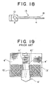
In a separable bottom end stop 6' for a slide fastener
shown in Fig. 19, the outer peripheral edge of a reinforcement
piece 13' has a pointed corner, and thus the reinforcement piece
13' easily catches other objects and is easily stripped.
Further, because the reinforcement piece 13' is provided so as
to be wide and large toward the outer side edge of a fastener
tape 4', the portion of the fastener tape 4' where the
reinforcement piece 13' is provided becomes upright, and when
the slide fastener is attached to an object by sewing, the sewing
machine needle (not shown) contacts the reinforcement piece 13'
and the sewing machine needle breaks frequently. Further, when
the operation of joining or separating the separable bottom end
stop 6' is carried out, the external forces of twisting, bending
and the like are repeatedly applied to the reinforcement piece
13', and thus there is a possibility that the reinforcement
piece 13' may break off. Further, the reinforcement piece 13'
whose outer side projects in an arc-shape toward a lower end
of the tape becomes thick and thus the sewing machine needle
may break, and there is also a problem that the reinforcement
piece 13' catches other objects easily.
SUMMARY OF THE INVENTION
The invention is contrived with considering the
above-described problems, and a main object of the invention
is to provide a slide fastener having a separable bottom end
stop in which a reinforcement piece in the separable bottom end
stop is directly molded to a fastener tape by injection molding,
thereby reducing cost of a product; to improve flexibility of
the reinforcement piece; and to provide a high quality product
being difficult to be stripped and damaged in which the sewing
machine needle is not broken easily upon sewing, thereby
improving production efficiency.
Another object of the invention is to provide a slide
fastener having a separable bottom end stop in which a
projecting start edge portion of the reinforcement piece, which
receives the most load when an external force which can deform
the reinforcement piece is applied, is reinforced, and the
reinforcement piece is not broken easily.
Still another object of the invention is to provide a slide
fastener having a separable bottom end stop in which because
of an inclined portion of the reinforcement piece, the frequency
with which the reinforcement piece catches other objects is
reduced, thereby making stripping of the reinforcement piece
difficult, and the bottom end stop comprises an excellent and
strong reinforcement piece whose configuration is novel in
terms of design.
Further object of the invention is to provide a slide
fasteners having a separable bottom end stop in which a lower
end of the fastener tape is prevented from fraying easily, and
thus a beautiful condition is retained for a long period of time.
Another object of the invention is to provide a slide
fastener having a separable bottom end stop in which a molten
resin is thoroughly permeated from the projecting start edge
portion of the reinforcement piece to an edge portion at the
outer side portion when the reinforcement piece is molded by
injection molding, and thereby the reinforcement piece is
molded easily.
Other objects are made clear from the following
description of the embodiments.
In order to attain the above-described objects, according
to the main features of the invention, there is provided a slide
fastener having a separable bottom end stop in which respective
fastener elements are attached to opposing side edges of a pair
of fastener tapes, and the separable bottom end stop formed of
a synthetic resin and comprising a box pin, an insert pin and
a box is attached continuously to a lower end of the fastener
elements, and wherein sheet-like reinforcement pieces, which
project from opposing faces, that is, outer side faces of the
box pin and the insert pin and overhang respectively on at least
one surface of each of the fastener tapes, are provided at the
box pin and the insert pin, the box pin and the insert pin being
attached continuously to lower ends of the fastener elements;
each reinforcement piece has an inclined portion which inclines
towards an outer side edge of each fastener tape close to a lower
end of the fastener tape; the space between a lower end and the
inclined portion of the reinforcement piece is gradually
getting narrow toward an outer side portion of the reinforcement
piece; and the entire reinforcement piece has a substantially
triangular shape.
According to the above features, the following effects
are achieved that flexibility of the reinforcement piece is
improved, material used in the reinforcement piece is reduced
and this leads to a reduction in a product cost. In addition,
this results in a high quality product in which separation of
the reinforcement piece from the fastener tape and breakage
thereof is difficult and also, when the product is being sewn,
breakage of the sewing machine needle (not shown) is difficult,
and manufacturing efficiency is thereby improved.
Further, it is preferable that the reinforcement piece
provided on the other surface, for example a rear surface of
the fastener tape, is smaller than the reinforcement piece
provided on the one surface, for example a front surface of the
fastener tape, and both reinforcement pieces nip and hold the
fastener tape in the vicinity of one of the side faces of the
box pin and the insert pin such that the fastener tape is nipped
from both front and rear surfaces. Consequently, the following
effects are achieved that even if an external force that can
cause deformation of the reinforcement pieces is applied, a
projecting start edge portion of the reinforcement piece
provided on a front surface side of the fastener tape, where
the most load is applied, is reinforced by the reinforcement
piece provided on a rear surface side of the fastener tape, and
also the reinforcement piece on the front surface side cannot
break easily. Alternately, if the reinforcement pieces
disposed on both front and rear surfaces of the fastener tapes
are formed so as to have the same configuration, the following
effects are achieved that the reinforcement pieces do not break
easily at any portion thereof, when an external force which can
cause them to deform is applied thereto, and can be used for
a long period of time.
Further, it is possible that each of the reinforcement
pieces provided at the box pin and the insert pin is provided
with the inclined portion which inclines downward in a linear
form toward the outer side portion of said reinforcement piece
or the inclined portion which does not have a linear form, but
instead is bent inward in a substantially arc-shape. According
to the features, the following effects are achieved that the
frequency with which the inclined portion of the reinforcement
piece catches other objects is reduced and it becomes difficult
for the reinforcement piece to be stripped from the fastener
tape, and a novel design is achieved. Alternately, it is
preferable that an edge surface portion of each of the
reinforcement pieces provided at the box pin and the insert pin
is formed as a slope portion, which has a smooth downward incline
toward the front surface of the fastener tape, because the
frequency with which the entire reinforcement piece catches
other objects is reduced, an area for adhesion to the fastener
tape is ensured, stripping of the reinforcement piece is
prevented, and also a good feel to the touch is obtained.
In order to increase the attaching strength, it is
preferable that the outer side portion which extends in parallel
with the outer side edge of the fastener tape is formed between
the inclined portion and the lower end of the reinforcement
piece; the fastener tape is woven or knitted to allow
penetration of synthetic resins such that a portion of the
fastener tape, which the outer side portion of each of the
reinforcement pieces provided at the box pin and the insert pin,
that is, a front end portion of a side of each reinforcement
piece faces, is formed coarsely; and a welding yarn, which can
be thermally molten, is disposed at a portion of the fastener
tape, which the outer side portion of each of the reinforcement
pieces provided at the box pin and the insert pin, that is, a
front end portion of a side of each reinforcement piece faces,
so that a synthetic resin can be welded.
It is preferable that a plate-like projecting piece is
continuously provided with the outer side portion of each of
the reinforcement pieces provided at the box pin and the insert
pin, that is, with a front end portion of a side of each
reinforcement piece, and the projecting piece is attached so
as to hold and nip the outer side of the fastener tape.
Consequently, the following effects are achieved that an outer
tip portion of the reinforcement piece can be fixed firmly to
the fastener tape and the reinforcement piece never strip from
the fastener tape.
It is preferable that the lower end of each of the
reinforcement pieces provided at the box pin and the insert pin
aligns with the lower end of the fastener tape so as to reinforce
the fastener tape, because thread at a cut end of the fastener
tape can be prevented in advance from fraying easily and thus
the fastener tape can remain in a beautiful configuration for
a long period of time. Further, if except for a peripheral edge
portion which is continuous with the periphery of the
reinforcement piece, the entire inner face of each of the
reinforcement pieces provided at the box pin and the insert pin
is formed as a mesh having a mesh-like configuration, the
flexibility of the reinforcement piece is increased and the
amount of material used is reduced. Also, the design is made
excellent, and at the time of injection molding of the
reinforcement piece, thorough permeation of the molten resin
into the mesh portion can be carried out easily, thereby causing
the mold of the reinforcement piece to be simple.
According to the main features of the invention, there
is provided a slide fastener having a separable bottom end stop
in which respective fastener elements are attached to opposing
side edges of a pair of fastener tapes, and the separable bottom
end stop formed of a synthetic resin and comprising a box pin
and an insert pin is attached continuously to a lower end of
the fastener elements, wherein plate-like reinforcement pieces,
which project from opposing faces of the box pin and insert pin
respectively, that is, outer side surfaces thereof, and
overhang respectively on at least one surface of each of the
fastener tapes, are provided; each reinforcement piece has an
inclined portion which inclines toward an outer side edge close
to a lower end of the fastener tape; a space between a lower
end and the inclined portion of the reinforcement piece is
gradually getting narrow toward an outer side portion of the
reinforcement piece, and the entire reinforcement piece has a
substantially triangular shape. With the features, because
the reinforcement piece is disposed on only one surface of the
fastener tape, flexibility of the reinforcement piece is
improved and amount of material used is reduced and it leads
a reduction in cost of the product, and thus this invention
achieves remarkable effects.
BRIEF DESCRIPTION OF THE DRAWINGS
Fig. 1 is a front view of a main portion of a slide fastener
having a separable bottom end stop.
Fig. 2 is a front view of a main portion of a stringer,
in which a box pin is attached, of the same slide fastener having
the separable bottom end stop.
Fig. 3 is a bottom view of the stringer of the same slide
fastener having the separable bottom end stop.
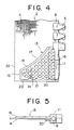
Fig. 4 is a front view of a main portion of a stringer,
in which an insert pin is attached, of the same slide fastener
having the separable bottom end stop.
Fig. 5 is a bottom view of the stringer of the same slide
fastener having the separable bottom end stop.
Fig. 6 is side view of a box of the same slide fastener
having the separable bottom end stop.
Fig. 7 is a cross sectional view of the box taken along
line VII-VII in Fig. 6 of the same slide fastener having the
separable bottom end stop.
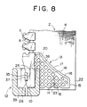
Fig. 8 is a partially cut front view showing a state that
the box pin is fit-inserted into the box of the same slide
fastener having the separable bottom end stop.
Fig. 9 is a partially cut front view showing a last state
in the same separable bottom end stop before the insert pin is
not inserted.
Fig. 10 is a partially cut front view showing a state in
the same separable bottom end stop that insert pin is set.
Fig. 11 is a front view of an end tip of the stringer
showing a modified example of the reinforcement piece.
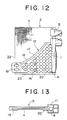
Fig. 12 is a front view of an end tip of the stringer
showing another modified example of the reinforcement piece.
Fig. 13 is a bottom view of the stringer of the same slide
fastener having the separable bottom end stop.
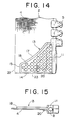
Fig. 14 is a front view of an end tip of the stringer
showing further modified example of the reinforcement piece.
Fig. 15 is a bottom view of the stringer of the same slide
fastener having the separable bottom end stop.
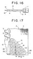
Fig. 16 is a bottom view of the stringer showing further
modified example of the reinforcement piece.
Fig. 17 is a front view of an end tip of the stringer
showing further modified example of the reinforcement piece.
Fig. 18 is a bottom view of the stringer of the same slide
fastener having the separable bottom end stop.
Fig. 19 is a front view of a known separable bottom end
stop.
DESCRIPTION OF THE PREFERRED EMBODIMENTS
The following is a detailed description of a slide
fastener having a separable bottom end stop of the invention,
with reference to the accompanying drawings.
In a slide fastener having a separable bottom end stop
of this invention, as shown in Fig. 1, a fastener chain 1 is
not a stopper with a lower stopper, but rather an open product.
That is to say, the slide fastener comprises a bottom end stop
6, in which right and left fastener stringers 2 can be separated
completely, and fastener elements 5 are attached to a core
portion 8 at a side edge of a fastener tape 4. Each of a box
pin 10 and an insert pin 11 is attached to the core portion 8,
such that the box pin 10 is attached continuously to a lower
portion of the fastener elements 5 of one stringer 2, while the
insert pin 11 is attached continuously to a lower portion of
the fastener elements 5 of the other stringer 2. Then, a box
12 is mounted to the box pin 10 and the separable bottom end
stop is completed.
In the box pin 10 attached to one stringer 2 of the fastener
chain 1, a flexible sheet-like reinforcement piece 13, which
overhang on a front surface of the fastener tape 4, is provided
integrally with a side face of the box pin 10. And in the insert
pin 11 attached to the other stringer 2 of the fastener chain
1, the flexible sheet-like reinforcement piece 13, which
overhang on the front surface of the fastener tape 4, is also
provided integrally with a side face of the insert pin 11. Then,
the fastener elements 5, the box pin 10, the insert pin 11 and
the reinforcement pieces 13 of the fastener chain 1 are
integrally molded with the fastener tapes 4 , respectively using
a thermoplastic resin by an injection molding means.
As shown in Figs. 2 to 5, the flexible sheet-like
reinforcement piece 13 is provided to each of the box pin 10
and the insert pin 11 so as to project outward from a side face
of each of the box pin 10 and the insert pin 11. As shown in
Fig.2, this reinforcement piece 13 at the box pin 10 is formed
with an inclined portion 17 which extends along the entire
length of the box pin 10 from vicinity of an upper end of the
box pin 10 to an outer side edge 22 of the fastener tape 4 close
to a lower end 23 of the fastener tape 4. A space between a
lower end 14 and the inclined portion 17 of the reinforcement
piece 13 is gradually getting narrow toward an outer side
portion 15 of the reinforcement piece 13 disposed in the
vicinity of the outer side edge 22 of the fastener tape 4. That
is, the reinforcement piece 13 is formed so as to be tapered
from a projecting start end at the side face of the box pin 10
toward the outer side portion 15. Thus the reinforcement piece
13 deforms easily in accordance with the deformation of the
fastener tape 4, and further an upper end portion of the
reinforcement piece 13 which tends most to catch other objects,
no longer does so, and stripping of the reinforcement piece 13
by the fastener tape 4 is prevented. Further, as shown in Fig.
3, the reinforcement piece 13 is molded on a front surface of
the fastener tape 4 by the injection molding means and it is
pressed and attached to the fastener tape 4.
The inclined portion 17 of the reinforcement piece 13 is
formed so as to be substantially linear in a downward direction
of the outer side edge 22 of the reinforcement piece 13.
Alternately, the reinforcement piece 13 is formed so as to be
slightly bent inwards to form an arc. Consequently, it hardly
catches other objects. Further, as shown in Fig. 3, an edge
portion of the reinforcement piece 13 has a slope portion 18
which slopes downward gently towards the fastener tape 4, and
thus the reinforcement piece is formed so as not to catch other
objects such as a sewing machine foot. As a result, the
reinforcement piece 13 is prevented from being stripped from
the fastener tape 4. Further, the outer side portion 15 which
extends in parallel with the outer side edge 22 of the fastener
tape 4 is provided in a space between the inclined portion 17
and the lower end 14 of the reinforcement piece 13, and thus
the reinforcement piece 13 is no more tapered than necessary.
That is to say, a front end of the reinforcement piece is no
longer formed as a sharp angle. As a result, an area for
pressing and attaching the outer side portion 15 to the fastener
tape 4 is secured, and thus stripping of the reinforcement piece
13 becomes difficult with the outer side portion 15. Except
for a peripheral edge portion which is continuous to the
periphery of reinforcement piece 13, the entire inner face is
formed as a mesh 16, and the mesh 16 provides the reinforcement
piece 13 with flexibility and elasticity.
The mesh 16 is formed by a tape press member which
positions the fastener tape 4 in the molding cavity of a mold,
such that when the reinforcement piece 13 is molded by injection
molding, the fastener tape 4 does not deform due to injection
pressure. Because the reinforcement piece 13 is formed in a
substantially triangular shape, and because it is formed as a
mesh 16, reduction in the amount of material can be achieved,
and further, the reinforcement piece 13 has an excellent design.
Meanwhile, a V-shaped groove 21 is formed so as to secure a space
for pressing a lower end 23 of the fastener tape 4 with a
tape-pressing member when the reinforcement piece 13 is molded
by injection molding.
As shown in Fig. 2, in the box pin 10, a middle portion
of the outer side face of the box pin 10 is formed as a concave
portion 25, and an engaging portion 26 is provided at a lower
end of the concave portion 25 and is engaged with an engaged
portion 37 provided on the box 12. Further, as shown in Fig.
3, the box pin 10 includes flexible sheet-like reinforcement
piece 20, which projects along the entire length of the box pin
10 on a rear side of the fastener tape 4 and overhangs on a surface
of the fastener tape 4 less than the reinforcement piece 13,
and the reinforcement piece 20 holds and nips the fastener tape
4 in the vicinity of the side face of the box pin 10 with the
reinforcement piece 13 on a front side of the fastener tape 4.
When the box pin 10 is fit-inserted into the box 12 from a lower
end thereof, the reinforcement piece 20 allows the box pin 10
to be guided smoothly. Further, when the slider 7 is moved
downwards from the upper end of the box pin 10 and abuts the
box 12 or when the slider 7 is moved upwards, the reinforcement
piece 20 functions to guide the slider 7 smoothly.
Further, when the reinforcement piece deforms in
accordance with the deformation of the fastener tape,
deformation of the fastener tape is suppressed relative to that
of the other portions at the projecting start edge portion of
the reinforcement piece which breaks off extremely easily, and
the reinforcement piece is reinforced such that breaking off
at the projecting start edge portion thereof is difficult.
The reinforcement piece 13 is provided to the insert pin
11 in the same manner as to the box pin 10. For example, as
shown in Fig. 4, the inclined portion 17 which inclines from
an area close to an upper end of the insert pin 11, that is,
from the same region as the box pin 10, to the outer side edge
22 of the fastener tape 4, close to the lower end 23 thereof.
The space between the lower end 14 and the inclined portion 17
of the reinforcement piece 13 is gradually getting narrowed
toward the outer side portion 15 of the reinforcement piece 13
disposed in the vicinity of the outer side edge 22 of the fastener
tape 4. The reinforcement piece 13 is molded on the front
surface of the fastener tape 4 by an injection molding means,
and pressed and attached onto the fastener tape 4. The inclined
portion 17 is formed so as to be substantially linear in a
downward direction of the outer side edge 22 of the
reinforcement piece 13 or formed so as to be bent inward in a
substantially arc-shape.
As shown in Fig. 5, the reinforcement piece 13 has a slope
portion 18 such that an edge portion of the reinforcement piece
slopes gently toward the front surface of the fastener tape 4,
so that the reinforcement piece is formed so as not to catch
other objects as a sewing machine foot. Further, an outer side
portion 15 which extends in parallel with the outer side edge
22 of the fastener tape 4 is provided between the inclined
portion 17 and the lower end 14 of the reinforcement piece 13.
Also, as shown in Fig. 5, a flexible sheet-like reinforcement
piece 20, which is projected along the entire distance of the
insert pin 11 and overhangs on the surface of the fastener tape
4 with a smaller area than that of the reinforcement piece 13,
is provided on the rear surface of the insert pin 11. The
reinforcement piece 20 holds and nips the fastener tape 4 in
the vicinity of the side face of the insert pin 11 with the
reinforcement piece 13, which is on the front surface. In
addition, the reinforcement 13 at the side of the insert pin
11 has the same configuration of the reinforcement piece at the
side of the box pin and functions similarly, such that entire
face except for the peripheral edge portion of the reinforcement
piece 13 is formed as a mesh 16.
Next, the box 12 will be described. As shown in Figs.
6 and 7, the periphery of the box 12 is surrounded by a front
wall 30, a back wall 31, side walls 32, and a bottom wall 33.
An upper side of the box is provided with an opening portion
34 which is opened and a partitioning wall 35 is provided in
the center of the box 12 between the front wall 30 and the back
wall 31, thus providing a box pin insert portion 38 , and an insert
pin insert portion 39 to the right and left of the box 12. The
partitioning wall 35 is engaged with the concave portion 25 of
the box pin 10 and the engaged portion 37 which is engaged with
the engaging portion 26 of the concave portion 25 is provided
at a lower end of the partitioning wall. Further, a side groove
36 is provided at the center of each of the side walls 32 in
a longitudinal direction thereof, and the reinforcement piece
13 disposed at the fastener tape 4 can be fit-inserted therein.
The material for the box 12 is the same material used for the
box pin 10, the insert pin 11, and the reinforcement piece 13.
The separable bottom end stop 6 is assembled in the
following manner. As shown in Fig. 8, when the box pin 10 which
is attached to an end portion of the stringer 2 is fit-inserted
into the box pin insertion portion 38 of the box pin 12, and
the concave portion 25 which is provided on the side face of
the box pin 10 is fit-inserted into the partitioning wall 35
of the box 12. The engaging portion 26 and the engaged portion
37 are engaged and fixed, and then the box 12 can be attached
to the stringer 2. It is to be noted that the box 12 can be
easily attached to the box pin 10 by a manual operation.
The operation of the separable bottom end stop 6 is as
described in the following. As shown in Fig. 9, at the box 12
which is attached to the stringer 2 on which the box pin 10 is
mounted, the slider 7 which is inserted through the same
stringer 2 is pulled down so as to abut the box 12, and in this
state, the insert pin 11 which is mounted to the other stringer
2 is fit-inserted into the slider 7 and the insert pin insertion
portion 39 of the box 12 by gripping the reinforcement piece
13. Then the slider 7 is pulled up and slid, and both fastener
elements 5 are coupled with each other as shown in Fig. 10, and
the coupled state of the fastener chain 1 is thereby achieved.
In order to separate and release the fastener chain 1, after
the slider 7 is pulled down to the box 12, the reinforcement
piece 13 at the side of the insert pin 11 is gripped and the
insert pin 11 is taken out from the insert pin insertion portion
39 of the box 12 and from the slider 7, and then both stringers
2 are separated.
In the modified example of the reinforcement piece 13
shown Fig. 11, at a portion of the reinforcement piece which
is close to the outer side edge 22 of fastener tape 4, for example
a portion A shown in the drawing, part of the warp yarns are
omitted, or alternately part of the warp yarns are pulled toward
one side edge of the fastener tape 4, and the fastener tape 4
is formed with a rough weaving or knitting structure in which
air space of fiber passing through the fastener tape 4 in the
direction of the front and rear surfaces of the fastener tape
is larger than that of the other portions. In addition, the
reinforcement piece 13 is molded by injection molding to the
fastener tape 4, the resin of the outer side portion 15 of the
reinforcement piece 13 can be easily permeated and solidified
through the roughness within the weaving or knitting structure.
Thus the outer side portion 15 of the reinforcement piece 13
can be fixed firmly to the fastener tape 4 and stripping of the
reinforcement piece 13 from the fastener tape 4 can be prevented
certainly. Further, the lower end 14 of the reinforcement piece
13 in the vicinity of the box pin 10 or the insert pin 11 is
not provided with the V-shaped grooves 21 formed therein. As
a result, breakage of the projecting start edge portion of the
reinforcement piece 13 becomes difficult.
Further, a welding yarn, which is formed from a synthetic
fiber yarn having a same level of or lower melting point as that
of the same resin used for the reinforcement piece 13, is woven
as a warp yarn or knitted as a warp knitted yarn at a portion
A, a portion of the fastener tape 4 being close to the outer
side edge 22 of the fastener tape 4. And the, when the
reinforcement piece 13 is molded by injection molding, the
welding yarn is melted and integrated with the reinforcement
piece 13. As a result, the outer side portion 15 of the
reinforcement piece 13 is firmly fixed and stripping of the
reinforcement piece 13 from the fastener tape 4 is prevented.
Figs. 12 and 13 show a modified example of the
reinforcement piece 13 in which a sheet-like projecting piece
19 is continuously provided with the outer side portion 15 of
the reinforcement piece 13, and as shown in Fig. 13, the
projecting piece 19 is extended to the rear surface of the
fastener tape 4, such that it holds and nips the outer side edge
22 of fastener tape 4. And this, the reinforcement piece 13
is firmly fixed to fastener tape 4 and stripping of the
reinforcement piece 13 from the fastener tape 4 is prevented
certainly.
In the reinforcement piece 13 modified examples shown in
Figs. 14 and 15, injection molding of the reinforcement piece
13 is carried out such that the lower end 14 of the reinforcement
piece 13 and the lower end 23 of the fastener tape 4 are aligned,
and the lower end 14 and the lower end 23 are welded together
in order to prevent the thread from fraying at the lower end
23 which is a cut end of the fastener tape 4. One means for
aligning the lower end 14 of the reinforcement piece 13 and the
lower end 23 of the fastener tape 4 is to mold the lower end
14 of the reinforcement pieces 13 on the fastener tape 4 such
that it extends so as to project further downward than the box
pin 10 or the insert pin 11. After the molding, this extended
portion is cut together with the fastener tape 4 and thereby
caused to be aligned. The cutting is carried out by press-cutting.
and the lower end 14 of the reinforcement piece 13 and
the lower end 23 of the fastener tape 4 are melted and
respectively welded together by the heat generated by the
press-cutting. In addition, a slope portion 18 is formed at
an edge portion of the reinforcement piece 13, which is
continuous with the inclined portion 17, the outer side portion
15 and the lower end 14, and thus the reinforcement piece 13
becomes difficult to catch other objects.
In the reinforcement piece 13 of the modified example
shown in Fig. 16, reinforcement pieces 13 and 20 which have the
same configuration are molded by injection molding onto both
front and rear surfaces of the fastener tape 4, and the fastener
tape 4 is held and nipped by the reinforcement pieces 13 and
20. Thus even if the reinforcement pieces 13 and 20 deform in
accordance with the deformation of the fastener tape 4, breakage
at all the portions of the reinforcement pieces 13 and 20 becomes
difficult.
The difference between the reinforcement piece 13 in the
modified example shown in Figs. 17 and 18 and the example of
the first embodiment is the shape of the inclined portion 17
of the reinforcement piece 13. As shown in Fig. 18, the flexible
sheet-like reinforcement piece 13 provided only on the front
surface of the fastener tape 4, is molded integrally by
injection molding from the side face of the box pin 10 or the
insert pin 11. As shown in Fig. 17, the inclined portion 17,
which inclines in a substantially linear shape from the side
of an upper end of the box pin 10 or the insert pin 11 toward
the outer side edge 22 close to the lower end 23 of the fastener
tape 4, is provided, and the space between the lower end 14 of
the reinforcement piece 13 and the inclined portion 17 is
gradually getting narrow toward the outer side portion 15 of
the reinforcement piece 13, and the entire reinforcement piece
13 has a substantially triangular shape.
Finally, as a thermoplastic resin used for the fastener
elements 5, the box pin 10, the insert pin 11, the reinforcement
pieces 13 and 20, the box 12 and an upper stopper in the fastener
chain 1, a polyactetal resin is preferably used when
consideration is given to molding and color matching of the
members. In order to make the reinforcement pieces 13 and 20
flexible, a soft acetal resin or a soft acetal copolymer resin
is used. Especially, by using a resin having the specific
properties of a tensile strength (Mpa) in the range of 45 to
60, a pull and stretch (%) in the range of 60 to 300, and a melt
index (g/min) in the range of 6 to 25, the reinforcement piece
13 which has the smallest thickness of the resin members listed
above, can be provided with a suitable amount of flexibility.
Thus, a slide fastener having a separable bottom end stop, in
which the fastener chain 1 is soft to the touch, is completed.