EP0992201A1 - Separable bottom end stop of slide fastener - Google Patents
Separable bottom end stop of slide fastener Download PDFInfo
- Publication number
- EP0992201A1 EP0992201A1 EP99307472A EP99307472A EP0992201A1 EP 0992201 A1 EP0992201 A1 EP 0992201A1 EP 99307472 A EP99307472 A EP 99307472A EP 99307472 A EP99307472 A EP 99307472A EP 0992201 A1 EP0992201 A1 EP 0992201A1
- Authority
- EP
- European Patent Office
- Prior art keywords
- box
- pin
- reinforcing
- fastener
- portions
- Prior art date
- Legal status (The legal status is an assumption and is not a legal conclusion. Google has not performed a legal analysis and makes no representation as to the accuracy of the status listed.)
- Granted
Links
Images


Classifications
-
- A—HUMAN NECESSITIES
- A44—HABERDASHERY; JEWELLERY
- A44B—BUTTONS, PINS, BUCKLES, SLIDE FASTENERS, OR THE LIKE
- A44B19/00—Slide fasteners
- A44B19/24—Details
- A44B19/26—Sliders
- A44B19/30—Sliders with means for locking in position
-
- A—HUMAN NECESSITIES
- A44—HABERDASHERY; JEWELLERY
- A44B—BUTTONS, PINS, BUCKLES, SLIDE FASTENERS, OR THE LIKE
- A44B19/00—Slide fasteners
- A44B19/24—Details
- A44B19/38—Means at the end of stringer by which the slider can be freed from one stringer, e.g. stringers can be completely separated from each other
- A44B19/382—"Two-way" or "double-acting" separable slide fasteners
-
- A—HUMAN NECESSITIES
- A44—HABERDASHERY; JEWELLERY
- A44B—BUTTONS, PINS, BUCKLES, SLIDE FASTENERS, OR THE LIKE
- A44B19/00—Slide fasteners
- A44B19/24—Details
- A44B19/38—Means at the end of stringer by which the slider can be freed from one stringer, e.g. stringers can be completely separated from each other
-
- Y—GENERAL TAGGING OF NEW TECHNOLOGICAL DEVELOPMENTS; GENERAL TAGGING OF CROSS-SECTIONAL TECHNOLOGIES SPANNING OVER SEVERAL SECTIONS OF THE IPC; TECHNICAL SUBJECTS COVERED BY FORMER USPC CROSS-REFERENCE ART COLLECTIONS [XRACs] AND DIGESTS
- Y10—TECHNICAL SUBJECTS COVERED BY FORMER USPC
- Y10T—TECHNICAL SUBJECTS COVERED BY FORMER US CLASSIFICATION
- Y10T24/00—Buckles, buttons, clasps, etc.
- Y10T24/25—Zipper or required component thereof
- Y10T24/2593—Zipper or required component thereof including complementary, aligning means attached to ends of interlocking surfaces
- Y10T24/2595—Zipper or required component thereof including complementary, aligning means attached to ends of interlocking surfaces having specific mounting connection or reinforcing structure at connection
Definitions
- the present invention relates to an open type of slide fastener which can immediately double as a slide fastener having a bottom end stop for upward opening or as a slide fastener having a bottom end stop for both-way opening by using a box or a slider for reverse opening in a bottom end stop of a slide fastener.
- a bottom end stop for reverse opening and made of thermoplastic resin as disclosed in Japanese Utility Model Publication No. 61-44647, wherein a stopper 7' projecting in an L shape is integrally molded with an end portion of an outer side edge portion 25' at a side of a box pin 3' such that a tip end of a flange 17' of a slider for reverse opening 16' can abut on the stopper 7', as shown in FIG. 12.
- the box pin 103 and the box 118 of the bottom end stop are fixed to each other by fitting the lower end of the partitioning plate 132 formed on the side face of the box 118 in the fitting recessed portion 133 formed on the reinforcing plate 108 on the side of the box pin 103 and by fitting the projection formed on the upper face of the box pin 103 in the recess stepped portion 131 formed on the back face of the upper plate of the box 118.
- a fixing mechanism is merely fitting means, the fixing mechanism is unstable and may be broken under rough use.
- a slider used for reverse opening has to be a specific slider defined at a back face of an upper wing plate of the slider with the recess stepped portion to be fitted over the projection formed on the upper face of the box pin. Therefore, when the bottom end stop is applied to a reverse-opening type of product, a slider of the same type as a normal slider, i.e., a slider for upward opening can not be used.
- the bottom end stop shown in FIG. 12 is intended for reverse opening, the bottom end stop can not immediately respond to the bottom end stop to which the box 118 is attached. Moreover, because the outer side edge portions 25' on the sides of the box pin 3' and a separable pin 4' are flat, it is difficult to hold the fastener chain in a bottom end stop operation and a smooth operation can not be expected.
- the present invention has been accomplished with the above-described problems in view and it is a main object of the invention to provide a reversely openable bottom end stop of a slide fastener wherein a both-way opening type of slide fastener and an upward opening type of slide fastener can be supplied in immediate response to demand.
- a portion of a fastener chain where the bottom end stop is disposed can be easily held, reverse opening operation or bottom end stop operation can be carried out smoothly, and the slider for reverse opening can be stopped properly.
- An object of the invention is to provide a reversely openable bottom end stop of a slide fastener, wherein the slider for reverse opening reliably guides the bottom end stop at an end of the fastener chain in a closing direction, i.e. sideways, a stopping function of the slider for reverse opening is improved, and an end portion has favorable appearance.
- Another object of the invention is to provide a reversely openable bottom end stop of a slide fastener having guide portions which are for smooth sliding of the slider for reverse opening and do not hinder mounting of the box.
- An object of the invention is to provide a reversely openable bottom end stop of a slide fastener, wherein mounting operation of a box is facilitated such that the box can be easily inserted into the box pin and a stopping function of the slider for reverse opening is not hindered.
- the invention has an object to provide a reversely openable bottom end stop, wherein a portion of a fastener chain to which the bottom end stop is mounted is reinforced, the end portion of the fastener chain can be easily held, a smooth bottom end stop operation can be carried out, and the bottom end stop is suitable to a slide fastener of a type wherein a fastener element is mounted to one face of the fastener tape.
- Another object of the invention is to provide a slide fastener mounted with a bottom end stop, wherein the box is firmly fixed to an end portion of a fastener stringer.
- a reversely openable bottom end stop of a slide fastener wherein a box pin 3 and a separable pin 4 are respectively molded on end portions of fastener stringers 1, 1 by injection molding or extrusion means by using thermoplastic resin, thin guide portions 5 are respectively and integrally molded at sides of the box pin 3 and the separable pin 4, projecting reinforcing streak portions 6 are integrally molded at sides of the guide portions 5, and a stopper 7 extending from a tip end of the box pin 3 to a tip end of the reinforcing streak portion 6 and is integrally molded on an upper face of the guide portion 5.
- the stopper 7 laterally formed between the box pin 3 and the reinforcing streak portion 6 is in a V shape and projecting higher than the reinforcing streak portion 6, and the reinforcing streak portion 6 is integrally molded to project from both front and back surfaces of a fastener tape 2.
- the thin guide portions 5 formed at the sides of the box pin 3 and the separable pin 4 are integrally molded between the box pin 3 and the reinforcing streak portion 6 and between the separable pin 4 and the reinforcing streak portion 6 to have such widths that at least flanges 17 of a slider 16 can slide in the guide portions 5.
- the stopper 7 laterally formed between the box pin 3 and the reinforcing streak portion 6 is defined at an intermediate portion of the stopper 7 with a stepped portion 10 and projects higher on a reinforcing streak portion 6 side and lower on a box pin 3 side.
- reinforcing portions 8 are formed by welding thermoplastic resin films to opposite faces of end portions of the pair of fastener tapes 2 by ultrasonic machining or the like, the reinforcing streak portions 6 are formed on both front and back surfaces of the reinforcing portions 8 of the left and right fastener stringers 1, and the box pin 3, the guide portion 5, and the stopper 7 are integrally molded on a surface of the reinforcing portion 8 of the one fastener stringer 1, and the separable pin 4 and the guide portion 5 are integrally molded on a surface of the reinforcing portion 8 of the other fastener stringer 1.
- reinforcing portions 8 are formed by welding thermoplastic resin films to opposite faces of end portions of the pair of fastener tapes 2 by ultrasonic machining or the like, the box pin 3, the guide portion 5, the stopper 7, and the reinforcing streak portion 6 are integrally molded on both front and back surfaces of the reinforcing portion 8 of the one fastener stringer 1 so as to be symmetric with respect to a fastener tape plane, and the separable pin 4, the guide portion 5, and the reinforcing streak portion 6 are integrally molded on both front and back surfaces of the reinforcing portion 8 of the other fastener stringer 1 so as to be symmetric with respect to the fastener tape plane.
- a box 18 is substantially square and defined at a center of the box 18 with a partitioning portion 19, a box pin insertion hole 22 is formed at one side of the partitioning portion 19, a separable pin insertion hole 23 is formed at the other side of the partitioning portion 19, a streak of inserting groove 21 for the fastener tape 2 is formed at a side portion of each of the box pin insertion hole 22 and the separable pin insertion hole 23, a locking hole 24 which is for the stopper 7 and is wider than the inserting grooves 21 is connected to a tip end of the inserting groove 21 of the box pin insertion hole 22, the box pin 3 is fitted into the box 18, the stopper 7 is locked in the locking hole 24 of the box 18, and opposed faces of the box 18 and the box pin 3 are welded to each other by ultrasonic machining or the like.
- the slider 16 for reverse opening and the slider 16 for upward opening are slid and fitted over the fastener stringer 1 mounted with the box pin 3 reversely to each other, i.e., to face each other reversely, and a tip end of the flange 17 of the slider 16 for reverse opening can abut on the stopper 7 formed to project from a face of the guide portion 5.
- FIG. 1 is a perspective view of a reversely openable bottom end stop.
- FIG. 2 is a front view of a reversely openable bottom end stop equipped with a box with a portion cut.
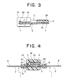
- FIG. 3 is a sectional view taken along a line A-A in FIG. 2.
- FIG. 4 is a sectional view taken along a line B-B in FIG. 2.
- FIG. 5 is a front view of a reversely openable bottom end stop equipped with a slider for reverse opening with a portion cut.
- FIG. 6 is a perspective view of a fastener stringer showing amodification of a stopper.
- FIG. 7 is a front view of the fastener chain equipped with a box with a portion cut.
- FIG. 8 is a front view of the fastener chain equipped with a slider for reverse opening with a portion cut.
- FIG. 9 is a front view of the fastener chain equipped with a bottom end stop which is symmetric with respect to a fastener tape plane with a portion cut.
- FIG. 10 is a bottom view of an essential portion by cutting out only the box of the bottom end stop of FIG. 9.
- FIG. 11 is a perspective view of a known bottom end stop of a slide fastener.
- FIG. 12 is a front view of a known bottom end stop for reverse opening with a portion cut.
- the bottom end stop of the invention can double as a bottom end stop for reverse opening.
- left and right fastener stringers 1, 1 are formed with reinforcing portions 8 by welding thermoplastic resin films made of polyamide, polyethylene, or the like or laminated thermoplastic resin films to fastener tapes 2 by ultrasonic machining or by causing thermoplastic resin liquid to permeate the fastener tapes 2 and hardening the liquid to firmly fix and reinforce end portions of the fastener tapes 2 in order to mold a box pin 3 and a separable pin 4 respectively on the end portions of the fastener tapes 2.
- a reinforcing process is carried out as follows.
- a coil-shaped fastener element 12 is sewn on a longitudinal edge portion of each the fastener tape 2 by using a sewing yarn 26.
- the coil-shaped fastener element 12 is formed from a monofilament which is a synthetic fiber made of polyamide, polyester, or the like.
- a tip end portion of the coil-shaped fastener element 12 is cut and removed from the fastener tape 2 and each the reinforcing portion 8 is molded such that the thermoplastic resin film envelops a core thread 25 and the sewing yarn 26 remaining at the cut portion.
- each the reinforcing portion 8 i.e., a tip end of the reinforcing portion 8 on a side of the coil-shaped fastener element 12 is notched to a proper size and the box pin 3 or the separable pin 4 is molded at the notched portion.
- the box pin 3 is a rectangular parallelepiped, has substantially the same height as the coil-shaped fastener element 12, and substantially accords with outer sides of connecting portions 14 of the coil-shaped fastener element 12.
- a side end of the box pin 3 substantially accords with a longitudinal edge of the fastener tape 2.
- a thin guide portion 5 which is adjacent to a side of the box pin 3 and has such a width that a flange 17 of the slider 16 can freely slide in the guide portion 5 is molded.
- a reinforcing streak portion 6 in a shape of a rectangular parallelepiped which projects from front and back faces of the fastener tape 2 and is lower than the box pin 3 is molded in adjacent to a side of the guide portion 5 and in parallel to the box pin 3.
- a V-shaped stopper 7 extending from a tip end of the box pin 3 and a tip end of the reinforcing streak portion 6 and lower than the box pin 3 and higher than the reinforcing streak portion 6 is molded on an upper face of the guide portion 5.
- a plurality of small projections 9 are formed to project from half of the tip end side portion of an upper face of the box pin 3.
- the small projections 9 are molded to have such a height that a slider 16 for reverse opening can slide freely without hindrance and are formed to be melted and joined to a box 18.
- the tip end of the box pin 3 bends slightly inward to guide a flange 20 of the box 18 or the flange 17 of the slider 16 for reverse opening sideways.
- the box pin 3, the guide portion 5, the reinforcing streak portion 6, and the stopper 7 are integrally molded by injection molding processing or extrusion processing by using thermoplastic rein such as polyacetal, polyamide, polypropylene, polybutyrene terephthalate, or the like.
- a portion of the reinforcing portion 8 formed at the end portion of the fastener tape 2 by removing the coil-shaped fastener element 12 is notched and the separable pin 4 in a shape of a rectangular parallelepiped is molded at the notched portion to have substantially the same height as the coil-shaped fastener element 12 and to substantially accord with outer sides of connecting portions 14 of the coil-shaped fastener element 12.
- a side end of the separable pin 4 substantially accords with a longitudinal edge of the fastener tape 2.
- a thin guide portion 5 which is adjacent to a side of the separable pin 4 and has such a width that a flange 17 of the slider 16 can freely slide in the guide portion 5 is molded.
- a reinforcing streak portion 6 in a shape of a rectangular parallelepiped which projects from front and back faces of the fastener tape 2 and is lower than the separable pin 4 and higher than the guide portion 5 is molded in adjacent to a side of the guide portion 5 and substantially in parallel to the separable pin 4.
- a tip end of the molded separable pin 4 bends slightly inward and a wall of the reinforcing streak portion 6 facing the separable pin 4 is slightly recessed such that the tip end and the opposite wall can be easily fitted in the box 18 or the slider 16 for reverse opening.
- the separable pin 4, the guide portion 5, and the reinforcing streak portion 6 are integrally molded by injection molding processing or extrusion processing by using thermoplastic resin similar to that for the above--described box pin 3 and the like.
- the box 18 fitted over the box pin 3 has an outward form which is substantially a square and the fastener tapes 2 can be inserted into the flanges 20 on opposite sides of the box 18.
- the box 18 is defined with inserting grooves 21 slightly narrower than a thickness of the stopper 7, a partitioning portion 19 at a center of the box 18, and a box pin insertion hole 22 and a separable pin insertion hole 23 on the left and right of the partitioning portion 19.
- a locking hole 24 extending toward a surface of the box 18 is formed at a deepest portion of the inserting groove 21 of the flange 20 in the box pin insertion hole 22.
- the locking hole 24 is formed such that the stopper 7 formed to project from the upper face of the guide portion 5 and extends from the box pin 3 to the reinforcing streak portion 6 can be fitted into the locking hole 24.
- Mounting means of the box 18 to the box pin 3 is as follows.
- the box pin 3 is put to the box pin insertion hole 22 of the box 18, the stopper 7 projecting from the end portion of the guide portion 5 is put to the inserting groove 21 formed in the flange 20 of the box pin insertion hole 22, the box 18 is pushed and inserted while opening up the inserting groove 21 by force.
- the small projections 9 formed to project from the upper face of the box pin 3 are welded to the box 18 by applying ultrasonic machining to the surface of the box 18.
- the box 18 is firmly fixed to the box pin 3 and the bottom end stop is completed.
- a bottom end stop operation of the slide fastener is as follows.
- the slider 16 for upward opening is slid and put to the box 18 fixed to one of the fastener stringers 1. Then, the reinforcing streak portion 6 mounted to the other fastener stringer 1 is held to insert the separable pin 4 from a shoulder opening of the slider 16 for upward opening. After inserting the separable pin 4 to the separable pin insertion hole 23 of the box 18, the slider 16 for upward opening is slide toward an upper stop to close the slide fastener.
- An opening operation of the slide fastener is as follows. After the slider 16 for upward opening is slid and put to the box 18, the reinforcing streak portion 6 is held to draw the separable pin 4 out of the box 18 and the slider 16 for upward opening to separate the slide fastener into the left and right fastener stringers 1, 1.
- the slider 16 for upward opening and the slider 16 for reverse opening may be slid and fitted over the fastener stringer 1 mounted with the box pin 3, as shown in FIG. 5.
- the same type of slider can be used for the slider 16 for upward opening and the slider 16 for reverse opening.
- the slider 16 for reverse opening is slid and fitted from the shoulder opening of the slider 16 for reverse opening from the upper stop side of the fastener stringer 1 mounted with the box pin 3 toward the box pin 3.
- the flange 17 of the slider 16 for reverse opening is inserted along the guide portion 5 to abut on the stopper 7 and is fitted.
- the slider 16 for upward opening is slid and fitted over the fastener stringer 1 from a rear opening of the slider 16 and faces in a reverse orientation to the slider 16 for reverse opening, thereby completing the bottom end stop for reverse opening.
- a reverse opening bottom end stop operation of the slide fastener is as follows.
- the slider 16 for reverse opening fitted over one of the fastener stringers 1 is slid until the flange 17 abuts on and stops at the stopper 7 extending from the box pin 3 to the reinforcing streak portion 6 and projecting on the guide portion 5.
- the slider 16 for upward opening is slid and puts to the slider 16 for reverse opening until the slider 16 for upward opening slider 16 abuts on the slider 16 for reverse opening.
- the separable pin 4 of the other fastener stringer 1 is inserted from the shoulder opening of the slider 16 for upward opening and is inserted from the rear opening of the slider 16 for reverse opening until the separable pin 4 stops.
- the slider 16 for upward opening is slid toward the upper stop or the slider 16 for reverse opening is slid.
- An opening operation of the slide fastener is as follows.
- the slider 16 for reverse opening is slid down to the stopper 7 or the slider 16 for upward opening is put to the slider 16 for reverse opening.
- the separable pin 4 is drawn out of both the sliders 16, 16, thereby separating the slide fastener into the left and right fastener stringers 1, 1.
- FIG. 6 a modification of the stopper in the bottom end stop is shown in FIG. 6.
- the stopper 7 laterally extending from the tip end of the box pin 3 to the tip end of the reinforcing streak portion 6 is defined at its intermediate portion with a stepped portion 10.
- the stepped portion 10 is characterized in that it is lower on a box pin 3 side and higher on a reinforcing streak portion 6 side.
- the box 18 is in the same form as that in the preceding example as shown in FIG. 7 and the box 18 is mounted through the similar steps.
- the inserting groove 21 defined in the flange 20 is pushed into the stopper 7 and the locking hole 24 defined at the deepest portion of the inserting groove 21 is fitted into the stopper 7.
- ultrasonic machining is applied from an upper face of the box 18, thereby welding the small projections 9 on the upper face of the box pin 3 to fix the box 18 to the box pin 3.
- the bottom end stop is suitable to a slide fastener, wherein fastener elements 13 which are single bodies projecting from opposite faces of each the fastener tape 2 are mounted to a longitudinal edge of each the fastener tape 2 as the fastener element 11.
- the bottom end stop is defined at the end portions of the left and right fastener stringers 1 with reinforcing portions 8 formed by welding thermoplastic resin films or the like to the fastener tapes 2 where the fastener elements 13 which are the single bodies are removed.
- a box pin 3 connected to the single body fastener element 13 and having a rectangular shape in cross section is molded at the reinforcing portion 8 of one of the fastener stringer 1 so as to project from the surface and back face of the fastener tape 2.
- a guide portion 5, thinner than the box pin 3, which is adjacent to a side of the box pin 3 and has such a width that a flange 17 of the slider 16 for reverse opening can freely slide in the guide portion 5 is molded on the surface and back face of the fastener tape 2.
- a reinforcing streak portion 6 which is thinner than the box pin 3 and thicker than the guide portion 5 and is symmetric with respect to a fastener tape plane is molded in adjacent to a side of the guide portion 5 and on both front and back surfaces of the fastener tape 2.
- a stopper 7 which extends from the tip end of the box pin 3 to the tip end of the reinforcing streak portion 6, which is thinner on the box pin 3 side and as thick as the box pin 3 on the reinforcing streak portion 6 side, which is defined at its center with a stepped portion 10, and which projects in a V-shape is molded on a face of the guide portion 5 and on both front and back surfaces of the fastener tape 2.
- a separable pin 4 connected to the single body fastener element 13 and having a rectangular shape in cross section is molded at the reinforcing portion 8 of the other fastener stringer 1 so as to project from the surface and back face of the fastener tape 2 as shown in FIG. 10, for example, similarly to the box pin 3.
- a thin and plate-shaped guide portion 5 which is adjacent to a side of the separable pin 4 and has such a width that a flange 17 of the slider 16 for reverse opening can freely slide in the guide portion 5 is molded on the surface and back face of the fastener tape 2.
- a reinforcing streak portion 6 which is thicker than the guide portion 5 and thinner than the separable pin 4 is formed in adjacent to a side of the guide portion 5, thereby forming the fastener stringer 1 equipped with the separable pin 4.
- the box pin 3, guide portion 5, reinforcing streak portion 6, stopper 7 which are molded on the reinforcing portion 8 of the one fastener stringer 1 and the separable pin 4, guide portion 5, reinforcing streak portion 6 which are molded on the reinforcing portion 8 of the other fastener stringer 1 are integrally molded to be symmetric with respect to a fastener tape plane by injection molding processing or extrusion processing by using thermoplastic resin, respectively.
- the box 18 fitted over the box pin 3 has a substantially square outward form and is defined at centers of opposite flanges 20 with inserting grooves 21 which are slightly narrower than a thickness of the stopper 7 and into which the guide portions 5 can be inserted, as shown in FIGS. 9 and 10.
- a locking hole 24 which extends upward and downward and into which the stopper 7 can be fitted is formed at a deepest portion of the inserting groove 21 on the box pin 3 side.
- the box 18 is mounted to the box pin 3 through the similar steps to the above respective examples.
- the inserting groove 21 defined in the flange 20 of the box 18 is put to and pushed into the stopper 7 and the stopper 7 is fitted into the locking hole 24 defined at the deepest portion of the inserting groove 21 and extending upward and downward.
- the box 18 and the box pin 3 are welded and fixed to each other by ultrasonic machining or the like, thereby completing the upward opening type of bottom end stop.
- the slide fastener comprising single body fastener elements 13 and having the bottom end stop for both-way opening can be easily completed.
- a bottom end stop operation can be carried out through the similar steps to the above example.
- the upper stop is mounted to the fastener stringer 1 after sliding and fitting the slider 16 for upward opening or the slider 16 for reverse opening over the fastener stringer 1.
- the reversely openable bottom end stop of the slide fastener of the invention has the above-described structure and exhibits the following effects by the structure.
- the box pin and the separable pin made of thermoplastic resin are respectively mounted to end portions of fastener stringers, thin guide portions are respectively formed at sides of the box pin and the separable pin, projecting reinforcing streak portions are integrally formed at sides of the guide portions, and the stopper extending from the tip end of the box pin to the tip end of the reinforcing streak portion and is formed on an upper face of the guide portion. Therefore, the normal slider, i.e., the slider of the same type as the slider for upward opening can be applied as the slider for reverse opening without using a slider in a special form.
- an upward opening type or the both-way opening type of slide fastener having the bottom end stop can be supplied in immediate response to demand, thereby improving productivity.
- the fastener stringers can be easily held to smoothly carry out the operation.
- the slider for reverse opening fastens the bottom end stop sideways and is stopped properly at the end of the fastener chain and the fastener stringers can be further easily held.
- the box pin and the separable pin have such widths that at least flanges of the slider can slide in the guide portions, the box can be mounted without hindrance, the slider for reverse opening can stably slide at the end of the fastener chain, and the smooth bottom end stop operation or both-way opening operation can be carried out.
- the stopper laterally formed between the box pin and the reinforcing streak portion is defined at the intermediate portion of the stopper with the stepped portion and projects higher on the reinforcing streak portion side and lower on the box pin side, there is no hindrance to the locking function of the slider for reverse opening, the box can be easily connected to the box pin, and the bottom end stop can be easily produced.
- the reinforcing portions are formed by welding thermoplastic resin films to the opposite faces of the end portions of the fastener tapes, the reinforcing streak portions are integrally molded on both front and back surfaces of the reinforcing portions, and the box pin, the guide portion, and the stopper, or the separable pin and the guide portion are respectively and integrally molded on the face of the reinforcing portion. Therefore, the end portion of the fastener chain wherein the fastener elements are mounted to the one faces of the fastener tapes is reinforced, the end portion of the fastener chain can be easily held, and the bottom end stop operation and the both-way opening operation can be carried out smoothly.
- the reinforcing portions are formed by welding thermoplastic resin films to the opposite faces of the end portions of the fastener tapes, the box pin, the guide portion, the stopper, and the reinforcing streak portion, or the separable pin, the guide portion, and the reinforcing streak portion are respectively and integrally molded on both front and back surfaces of the reinforcing portion so as to be symmetric with respect to the fastener tape plane, the end portion of the fastener chain wherein the fastener elements are formed on the opposite faces of the fastener tapes is reinforced, the end portion of the fastener chain can be easily held, and the bottom end stop operation and the both-way opening operation can be carried out smoothly.
- the box is substantially square and defined at the center of the box with the partitioning portion, the box pin insertion hole is formed at one side of the partitioning portion, the separable pin insertion hole is formed at the other side of the partitioning portion, inserting grooves for the fastener tapes are formed at side portions of the box pin insertion hole and the separable pin insertion hole, the locking hole which is for the stopper and is wider than the inserting grooves is connected to the tip end of the inserting groove of the box pin insertion hole of the box, the box pin is fitted into the box, the stopper is locked in the locking hole, and opposed faces of the box and the box pin are welded to each other. Therefore, the box can be firmly fixed to the end portion of the fastener stringer and the strong bottom end stop can be produced easily.
- the convenient slide fastener for both-way opening wherein the slider for upward opening and the slider for reverse opening are slid and fitted over the fastener stringer and the slider for reverse opening has such a function that the slider can be stopped by using the tip end of the flange can be produced easily.
- the invention exhibits extremely remarkable effects.
Abstract
Description
- The present invention relates to an open type of slide fastener which can immediately double as a slide fastener having a bottom end stop for upward opening or as a slide fastener having a bottom end stop for both-way opening by using a box or a slider for reverse opening in a bottom end stop of a slide fastener.
- As this type of conventional open type of slide fastener, there is a reversely openable bottom end stop as disclosed in Japanese Utility Model Publication No. 55-44494, wherein reinforcing
plates 108 made of plastic are formed at end portions of left andright fastener stringers 101, abox pin 103 and aseparable pin 104 are respectively mounted to side ends of thereinforcing plates 108, aprotuberant portion 130 is formed on an upper face of thebox pin 103, a projection is formed at a lower end of theprotuberant portion 130, a rectangular fitting recessedportion 133 is formed on thereinforcing plate 108 on a side of thebox pin 103, apartitioning plate 132 is formed at a side face of abox 118 and fitted in the fitting recessedportion 133 of thereinforcing plate 108, a recess steppedportion 131 is formed at an outer end of a back face of an upper plate of thebox 118, and the projection formed at the lower end of thebox pin 103 is fitted in the recess steppedportion 131, thus fixing thebox pin 103 and thebox 118, for example, as shown in FIG. 11. - Furthermore, there is a bottom end stop for reverse opening and made of thermoplastic resin as disclosed in Japanese Utility Model Publication No. 61-44647, wherein a stopper 7' projecting in an L shape is integrally molded with an end portion of an outer side edge portion 25' at a side of a box pin 3' such that a tip end of a flange 17' of a slider for reverse opening 16' can abut on the stopper 7', as shown in FIG. 12.
- In the reversely openable bottom end stop described above and shown in FIG. 11, the
box pin 103 and thebox 118 of the bottom end stop are fixed to each other by fitting the lower end of the partitioningplate 132 formed on the side face of thebox 118 in the fitting recessedportion 133 formed on thereinforcing plate 108 on the side of thebox pin 103 and by fitting the projection formed on the upper face of thebox pin 103 in the recess steppedportion 131 formed on the back face of the upper plate of thebox 118. However, because a fixing mechanism is merely fitting means, the fixing mechanism is unstable and may be broken under rough use. When the bottom end stop is used as the bottom end stop for reverse opening, a slider used for reverse opening has to be a specific slider defined at a back face of an upper wing plate of the slider with the recess stepped portion to be fitted over the projection formed on the upper face of the box pin. Therefore, when the bottom end stop is applied to a reverse-opening type of product, a slider of the same type as a normal slider, i.e., a slider for upward opening can not be used. - Next, because the bottom end stop shown in FIG. 12 is intended for reverse opening, the bottom end stop can not immediately respond to the bottom end stop to which the
box 118 is attached. Moreover, because the outer side edge portions 25' on the sides of the box pin 3' and a separable pin 4' are flat, it is difficult to hold the fastener chain in a bottom end stop operation and a smooth operation can not be expected. - The present invention has been accomplished with the above-described problems in view and it is a main object of the invention to provide a reversely openable bottom end stop of a slide fastener wherein a both-way opening type of slide fastener and an upward opening type of slide fastener can be supplied in immediate response to demand. In each of the slide fasteners, a portion of a fastener chain where the bottom end stop is disposed can be easily held, reverse opening operation or bottom end stop operation can be carried out smoothly, and the slider for reverse opening can be stopped properly.
- An object of the invention is to provide a reversely openable bottom end stop of a slide fastener, wherein the slider for reverse opening reliably guides the bottom end stop at an end of the fastener chain in a closing direction, i.e. sideways, a stopping function of the slider for reverse opening is improved, and an end portion has favorable appearance.
- Another object of the invention is to provide a reversely openable bottom end stop of a slide fastener having guide portions which are for smooth sliding of the slider for reverse opening and do not hinder mounting of the box.
- An object of the invention is to provide a reversely openable bottom end stop of a slide fastener, wherein mounting operation of a box is facilitated such that the box can be easily inserted into the box pin and a stopping function of the slider for reverse opening is not hindered.
- The invention has an object to provide a reversely openable bottom end stop, wherein a portion of a fastener chain to which the bottom end stop is mounted is reinforced, the end portion of the fastener chain can be easily held, a smooth bottom end stop operation can be carried out, and the bottom end stop is suitable to a slide fastener of a type wherein a fastener element is mounted to one face of the fastener tape.
- It is an object of the invention to provide a reversely openable bottom end stop, wherein a portion of a fastener chain to which the bottom end stop is mounted is reinforced, the end portion of the fastener chain can be easily held, a smooth bottom end stop operation can be carried out, and the bottom end stop is suitable to a slide fastener of a type wherein a fastener element is mounted to project from opposite faces of each the fastener tape.
- Another object of the invention is to provide a slide fastener mounted with a bottom end stop, wherein the box is firmly fixed to an end portion of a fastener stringer.
- It is an object of the invention to provide a slide fastener mounted with a bottom end stop, wherein the slider for reverse opening and the slider for upward opening are employed.
- To achieve the above objects, according to the first aspect of the invention, there is provided a reversely openable bottom end stop of a slide fastener, wherein a
box pin 3 and aseparable pin 4 are respectively molded on end portions offastener stringers thin guide portions 5 are respectively and integrally molded at sides of thebox pin 3 and theseparable pin 4, projectingreinforcing streak portions 6 are integrally molded at sides of theguide portions 5, and astopper 7 extending from a tip end of thebox pin 3 to a tip end of thereinforcing streak portion 6 and is integrally molded on an upper face of theguide portion 5. - Preferably, the
stopper 7 laterally formed between thebox pin 3 and thereinforcing streak portion 6 is in a V shape and projecting higher than thereinforcing streak portion 6, and thereinforcing streak portion 6 is integrally molded to project from both front and back surfaces of afastener tape 2. - Further preferably, the
thin guide portions 5 formed at the sides of thebox pin 3 and theseparable pin 4 are integrally molded between thebox pin 3 and thereinforcing streak portion 6 and between theseparable pin 4 and thereinforcing streak portion 6 to have such widths that at leastflanges 17 of aslider 16 can slide in theguide portions 5. - Still preferably, the
stopper 7 laterally formed between thebox pin 3 and thereinforcing streak portion 6 is defined at an intermediate portion of thestopper 7 with astepped portion 10 and projects higher on areinforcing streak portion 6 side and lower on abox pin 3 side. - Yet preferably, reinforcing
portions 8 are formed by welding thermoplastic resin films to opposite faces of end portions of the pair offastener tapes 2 by ultrasonic machining or the like, thereinforcing streak portions 6 are formed on both front and back surfaces of the reinforcingportions 8 of the left andright fastener stringers 1, and thebox pin 3, theguide portion 5, and thestopper 7 are integrally molded on a surface of the reinforcingportion 8 of the one fastener stringer 1, and theseparable pin 4 and theguide portion 5 are integrally molded on a surface of the reinforcingportion 8 of theother fastener stringer 1. - Further preferably, reinforcing
portions 8 are formed by welding thermoplastic resin films to opposite faces of end portions of the pair offastener tapes 2 by ultrasonic machining or the like, thebox pin 3, theguide portion 5, thestopper 7, and thereinforcing streak portion 6 are integrally molded on both front and back surfaces of the reinforcingportion 8 of the one fastener stringer 1 so as to be symmetric with respect to a fastener tape plane, and theseparable pin 4, theguide portion 5, and thereinforcing streak portion 6 are integrally molded on both front and back surfaces of the reinforcingportion 8 of the other fastener stringer 1 so as to be symmetric with respect to the fastener tape plane. - Still preferably, a
box 18 is substantially square and defined at a center of thebox 18 with a partitioningportion 19, a boxpin insertion hole 22 is formed at one side of the partitioningportion 19, a separablepin insertion hole 23 is formed at the other side of the partitioningportion 19, a streak of insertinggroove 21 for thefastener tape 2 is formed at a side portion of each of the boxpin insertion hole 22 and the separablepin insertion hole 23, alocking hole 24 which is for thestopper 7 and is wider than theinserting grooves 21 is connected to a tip end of theinserting groove 21 of the boxpin insertion hole 22, thebox pin 3 is fitted into thebox 18, thestopper 7 is locked in thelocking hole 24 of thebox 18, and opposed faces of thebox 18 and thebox pin 3 are welded to each other by ultrasonic machining or the like. - Preferably, the
slider 16 for reverse opening and theslider 16 for upward opening are slid and fitted over thefastener stringer 1 mounted with thebox pin 3 reversely to each other, i.e., to face each other reversely, and a tip end of theflange 17 of theslider 16 for reverse opening can abut on thestopper 7 formed to project from a face of theguide portion 5. - FIG. 1 is a perspective view of a reversely openable bottom end stop.
- FIG. 2 is a front view of a reversely openable bottom end stop equipped with a box with a portion cut.
- FIG. 3 is a sectional view taken along a line A-A in FIG. 2.
- FIG. 4 is a sectional view taken along a line B-B in FIG. 2.
- FIG. 5 is a front view of a reversely openable bottom end stop equipped with a slider for reverse opening with a portion cut.
- FIG. 6 is a perspective view of a fastener stringer showing amodification of a stopper.
- FIG. 7 is a front view of the fastener chain equipped with a box with a portion cut.
- FIG. 8 is a front view of the fastener chain equipped with a slider for reverse opening with a portion cut.
- FIG. 9 is a front view of the fastener chain equipped with a bottom end stop which is symmetric with respect to a fastener tape plane with a portion cut.
- FIG. 10 is a bottom view of an essential portion by cutting out only the box of the bottom end stop of FIG. 9.
- FIG. 11 is a perspective view of a known bottom end stop of a slide fastener.
- FIG. 12 is a front view of a known bottom end stop for reverse opening with a portion cut.
- Embodiments of a reversely openable bottom end stop of a slide fastener of the present invention will be specifically described below by reference to the drawings.
- The bottom end stop of the invention can double as a bottom end stop for reverse opening. As shown in FIG. 1, left and
right fastener stringers portions 8 by welding thermoplastic resin films made of polyamide, polyethylene, or the like or laminated thermoplastic resin films to fastenertapes 2 by ultrasonic machining or by causing thermoplastic resin liquid to permeate thefastener tapes 2 and hardening the liquid to firmly fix and reinforce end portions of thefastener tapes 2 in order to mold abox pin 3 and aseparable pin 4 respectively on the end portions of thefastener tapes 2. - A reinforcing process is carried out as follows. A coil-
shaped fastener element 12 is sewn on a longitudinal edge portion of each thefastener tape 2 by using asewing yarn 26. The coil-shaped fastener element 12 is formed from a monofilament which is a synthetic fiber made of polyamide, polyester, or the like. A tip end portion of the coil-shaped fastener element 12 is cut and removed from thefastener tape 2 and each the reinforcingportion 8 is molded such that the thermoplastic resin film envelops acore thread 25 and thesewing yarn 26 remaining at the cut portion. - An inner side of each the reinforcing
portion 8, i.e., a tip end of the reinforcingportion 8 on a side of the coil-shaped fastener element 12 is notched to a proper size and thebox pin 3 or theseparable pin 4 is molded at the notched portion. Thebox pin 3 is a rectangular parallelepiped, has substantially the same height as the coil-shaped fastener element 12, and substantially accords with outer sides of connectingportions 14 of the coil-shaped fastener element 12. A side end of thebox pin 3 substantially accords with a longitudinal edge of thefastener tape 2. Athin guide portion 5 which is adjacent to a side of thebox pin 3 and has such a width that aflange 17 of theslider 16 can freely slide in theguide portion 5 is molded. Areinforcing streak portion 6 in a shape of a rectangular parallelepiped which projects from front and back faces of thefastener tape 2 and is lower than thebox pin 3 is molded in adjacent to a side of theguide portion 5 and in parallel to thebox pin 3. A V-shaped stopper 7 extending from a tip end of thebox pin 3 and a tip end of thereinforcing streak portion 6 and lower than thebox pin 3 and higher than thereinforcing streak portion 6 is molded on an upper face of theguide portion 5. - A plurality of
small projections 9 are formed to project from half of the tip end side portion of an upper face of thebox pin 3. Thesmall projections 9 are molded to have such a height that aslider 16 for reverse opening can slide freely without hindrance and are formed to be melted and joined to abox 18. The tip end of thebox pin 3 bends slightly inward to guide aflange 20 of thebox 18 or theflange 17 of theslider 16 for reverse opening sideways. - The
box pin 3, theguide portion 5, thereinforcing streak portion 6, and thestopper 7 are integrally molded by injection molding processing or extrusion processing by using thermoplastic rein such as polyacetal, polyamide, polypropylene, polybutyrene terephthalate, or the like. - On the other hand, similarly to the
box pin 3, a portion of the reinforcingportion 8 formed at the end portion of thefastener tape 2 by removing the coil-shaped fastener element 12 is notched and theseparable pin 4 in a shape of a rectangular parallelepiped is molded at the notched portion to have substantially the same height as the coil-shaped fastener element 12 and to substantially accord with outer sides of connectingportions 14 of the coil-shaped fastener element 12. A side end of theseparable pin 4, substantially accords with a longitudinal edge of thefastener tape 2. Athin guide portion 5 which is adjacent to a side of theseparable pin 4 and has such a width that aflange 17 of theslider 16 can freely slide in theguide portion 5 is molded. Areinforcing streak portion 6 in a shape of a rectangular parallelepiped which projects from front and back faces of thefastener tape 2 and is lower than theseparable pin 4 and higher than theguide portion 5 is molded in adjacent to a side of theguide portion 5 and substantially in parallel to theseparable pin 4. - A tip end of the molded
separable pin 4 bends slightly inward and a wall of thereinforcing streak portion 6 facing theseparable pin 4 is slightly recessed such that the tip end and the opposite wall can be easily fitted in thebox 18 or theslider 16 for reverse opening. Theseparable pin 4, theguide portion 5, and thereinforcing streak portion 6 are integrally molded by injection molding processing or extrusion processing by using thermoplastic resin similar to that for the above--describedbox pin 3 and the like. - As shown in FIGS. 2 to 4, the
box 18 fitted over thebox pin 3 has an outward form which is substantially a square and thefastener tapes 2 can be inserted into theflanges 20 on opposite sides of thebox 18. Thebox 18 is defined withinserting grooves 21 slightly narrower than a thickness of thestopper 7, a partitioningportion 19 at a center of thebox 18, and a boxpin insertion hole 22 and a separablepin insertion hole 23 on the left and right of the partitioningportion 19. Alocking hole 24 extending toward a surface of thebox 18 is formed at a deepest portion of theinserting groove 21 of theflange 20 in the boxpin insertion hole 22. Thelocking hole 24 is formed such that thestopper 7 formed to project from the upper face of theguide portion 5 and extends from thebox pin 3 to thereinforcing streak portion 6 can be fitted into thelocking hole 24. - It is also possible to form some streaks of small projecting portions on a ceiling portion of the box
pin insertion hole 22 of thebox 18 such that the small projecting portions can be welded to thebox pin 3. In this case, if the small projectingportions 9 are not formed on the upper face of thebox pin 3, thebox 18 and thebox pin 3 can be ultrasonically welded to each other. - Mounting means of the
box 18 to thebox pin 3 is as follows. Thebox pin 3 is put to the boxpin insertion hole 22 of thebox 18, thestopper 7 projecting from the end portion of theguide portion 5 is put to the insertinggroove 21 formed in theflange 20 of the boxpin insertion hole 22, thebox 18 is pushed and inserted while opening up the insertinggroove 21 by force. After thelocking hole 24 formed at the deepest portion of the insertinggroove 21 is fitted over thestopper 7 to fix thebox 18, thesmall projections 9 formed to project from the upper face of thebox pin 3 are welded to thebox 18 by applying ultrasonic machining to the surface of thebox 18. Thus, thebox 18 is firmly fixed to thebox pin 3 and the bottom end stop is completed. - A bottom end stop operation of the slide fastener is as follows. The
slider 16 for upward opening is slid and put to thebox 18 fixed to one of thefastener stringers 1. Then, the reinforcingstreak portion 6 mounted to theother fastener stringer 1 is held to insert theseparable pin 4 from a shoulder opening of theslider 16 for upward opening. After inserting theseparable pin 4 to the separablepin insertion hole 23 of thebox 18, theslider 16 for upward opening is slide toward an upper stop to close the slide fastener. - An opening operation of the slide fastener is as follows. After the
slider 16 for upward opening is slid and put to thebox 18, the reinforcingstreak portion 6 is held to draw theseparable pin 4 out of thebox 18 and theslider 16 for upward opening to separate the slide fastener into the left andright fastener stringers - Next, in the bottom end stop for reverse opening, the
slider 16 for upward opening and theslider 16 for reverse opening may be slid and fitted over thefastener stringer 1 mounted with thebox pin 3, as shown in FIG. 5. The same type of slider can be used for theslider 16 for upward opening and theslider 16 for reverse opening. Theslider 16 for reverse opening is slid and fitted from the shoulder opening of theslider 16 for reverse opening from the upper stop side of thefastener stringer 1 mounted with thebox pin 3 toward thebox pin 3. Theflange 17 of theslider 16 for reverse opening is inserted along theguide portion 5 to abut on thestopper 7 and is fitted. Then, theslider 16 for upward opening is slid and fitted over thefastener stringer 1 from a rear opening of theslider 16 and faces in a reverse orientation to theslider 16 for reverse opening, thereby completing the bottom end stop for reverse opening. - A reverse opening bottom end stop operation of the slide fastener is as follows. The
slider 16 for reverse opening fitted over one of thefastener stringers 1 is slid until theflange 17 abuts on and stops at thestopper 7 extending from thebox pin 3 to the reinforcingstreak portion 6 and projecting on theguide portion 5. Then, theslider 16 for upward opening is slid and puts to theslider 16 for reverse opening until theslider 16 forupward opening slider 16 abuts on theslider 16 for reverse opening. In this state, theseparable pin 4 of theother fastener stringer 1 is inserted from the shoulder opening of theslider 16 for upward opening and is inserted from the rear opening of theslider 16 for reverse opening until theseparable pin 4 stops. After the insertion, theslider 16 for upward opening is slid toward the upper stop or theslider 16 for reverse opening is slid. - An opening operation of the slide fastener is as follows. The
slider 16 for reverse opening is slid down to thestopper 7 or theslider 16 for upward opening is put to theslider 16 for reverse opening. Then, theseparable pin 4 is drawn out of both thesliders right fastener stringers - Next, a modification of the stopper in the bottom end stop is shown in FIG. 6. The
stopper 7 laterally extending from the tip end of thebox pin 3 to the tip end of the reinforcingstreak portion 6 is defined at its intermediate portion with a steppedportion 10. The steppedportion 10 is characterized in that it is lower on abox pin 3 side and higher on a reinforcingstreak portion 6 side. Thebox 18 is in the same form as that in the preceding example as shown in FIG. 7 and thebox 18 is mounted through the similar steps. The insertinggroove 21 defined in theflange 20 is pushed into thestopper 7 and the lockinghole 24 defined at the deepest portion of the insertinggroove 21 is fitted into thestopper 7. Then, ultrasonic machining is applied from an upper face of thebox 18, thereby welding thesmall projections 9 on the upper face of thebox pin 3 to fix thebox 18 to thebox pin 3. - When the
slider 16 for reverse opening is slid and fitted over thefastener stringer 1 and theseparable pin 4 is inserted into theslider 16 for reverse opening, the tip end of theflange 17 of theslider 16 for reverse opening is put to the projecting portion of thestopper 7, the projecting portion formed to be thick on the reinforcingstreak portion 6 side, thereby properly and firmly retaining theslider 16 for reverse opening, as shown in FIG. 8. - Another modification of the bottom end stop will be described. As shown in FIGS. 10 and 11, the bottom end stop is suitable to a slide fastener, wherein
fastener elements 13 which are single bodies projecting from opposite faces of each thefastener tape 2 are mounted to a longitudinal edge of each thefastener tape 2 as thefastener element 11. The bottom end stop is defined at the end portions of the left andright fastener stringers 1 with reinforcingportions 8 formed by welding thermoplastic resin films or the like to thefastener tapes 2 where thefastener elements 13 which are the single bodies are removed. - A
box pin 3 connected to the singlebody fastener element 13 and having a rectangular shape in cross section is molded at the reinforcingportion 8 of one of thefastener stringer 1 so as to project from the surface and back face of thefastener tape 2. Aguide portion 5, thinner than thebox pin 3, which is adjacent to a side of thebox pin 3 and has such a width that aflange 17 of theslider 16 for reverse opening can freely slide in theguide portion 5 is molded on the surface and back face of thefastener tape 2. A reinforcingstreak portion 6 which is thinner than thebox pin 3 and thicker than theguide portion 5 and is symmetric with respect to a fastener tape plane is molded in adjacent to a side of theguide portion 5 and on both front and back surfaces of thefastener tape 2. Astopper 7 which extends from the tip end of thebox pin 3 to the tip end of the reinforcingstreak portion 6, which is thinner on thebox pin 3 side and as thick as thebox pin 3 on the reinforcingstreak portion 6 side, which is defined at its center with a steppedportion 10, and which projects in a V-shape is molded on a face of theguide portion 5 and on both front and back surfaces of thefastener tape 2. - A
separable pin 4 connected to the singlebody fastener element 13 and having a rectangular shape in cross section is molded at the reinforcingportion 8 of theother fastener stringer 1 so as to project from the surface and back face of thefastener tape 2 as shown in FIG. 10, for example, similarly to thebox pin 3. A thin and plate-shapedguide portion 5 which is adjacent to a side of theseparable pin 4 and has such a width that aflange 17 of theslider 16 for reverse opening can freely slide in theguide portion 5 is molded on the surface and back face of thefastener tape 2. A reinforcingstreak portion 6 which is thicker than theguide portion 5 and thinner than theseparable pin 4 is formed in adjacent to a side of theguide portion 5, thereby forming thefastener stringer 1 equipped with theseparable pin 4. - The
box pin 3, guideportion 5, reinforcingstreak portion 6,stopper 7 which are molded on the reinforcingportion 8 of the onefastener stringer 1 and theseparable pin 4, guideportion 5, reinforcingstreak portion 6 which are molded on the reinforcingportion 8 of theother fastener stringer 1 are integrally molded to be symmetric with respect to a fastener tape plane by injection molding processing or extrusion processing by using thermoplastic resin, respectively. - The
box 18 fitted over thebox pin 3 has a substantially square outward form and is defined at centers ofopposite flanges 20 with insertinggrooves 21 which are slightly narrower than a thickness of thestopper 7 and into which theguide portions 5 can be inserted, as shown in FIGS. 9 and 10. A lockinghole 24 which extends upward and downward and into which thestopper 7 can be fitted is formed at a deepest portion of the insertinggroove 21 on thebox pin 3 side. - The
box 18 is mounted to thebox pin 3 through the similar steps to the above respective examples. The insertinggroove 21 defined in theflange 20 of thebox 18 is put to and pushed into thestopper 7 and thestopper 7 is fitted into the lockinghole 24 defined at the deepest portion of the insertinggroove 21 and extending upward and downward. Then, thebox 18 and thebox pin 3 are welded and fixed to each other by ultrasonic machining or the like, thereby completing the upward opening type of bottom end stop. - By sliding and fitting the
slider 16 for reverse opening and theslider 16 for upward opening which are symmetric with respect to the fastener tape plane over thefastener stringer 1 equipped with thebox pin 3 in a state wherein thesliders 16 reversely face each other, the slide fastener comprising singlebody fastener elements 13 and having the bottom end stop for both-way opening can be easily completed. A bottom end stop operation can be carried out through the similar steps to the above example. - In the respective embodiments, it is preferable that the upper stop is mounted to the
fastener stringer 1 after sliding and fitting theslider 16 for upward opening or theslider 16 for reverse opening over thefastener stringer 1. - The reversely openable bottom end stop of the slide fastener of the invention has the above-described structure and exhibits the following effects by the structure.
- According to the invention stated in the first aspect, the box pin and the separable pin made of thermoplastic resin are respectively mounted to end portions of fastener stringers, thin guide portions are respectively formed at sides of the box pin and the separable pin, projecting reinforcing streak portions are integrally formed at sides of the guide portions, and the stopper extending from the tip end of the box pin to the tip end of the reinforcing streak portion and is formed on an upper face of the guide portion. Therefore, the normal slider, i.e., the slider of the same type as the slider for upward opening can be applied as the slider for reverse opening without using a slider in a special form. As the result, an upward opening type or the both-way opening type of slide fastener having the bottom end stop can be supplied in immediate response to demand, thereby improving productivity. Moreover, in the bottom end stop operation, the fastener stringers can be easily held to smoothly carry out the operation.
- Since the stopper is in the V shape and projecting higher than the reinforcing streak portion, and the reinforcing streak portion projects from both front and back surfaces of the fastener tape, the slider for reverse opening fastens the bottom end stop sideways and is stopped properly at the end of the fastener chain and the fastener stringers can be further easily held.
- As the guide portions formed at the sides of the box pin and the separable pin have such widths that at least flanges of the slider can slide in the guide portions, the box can be mounted without hindrance, the slider for reverse opening can stably slide at the end of the fastener chain, and the smooth bottom end stop operation or both-way opening operation can be carried out.
- For the stopper laterally formed between the box pin and the reinforcing streak portion is defined at the intermediate portion of the stopper with the stepped portion and projects higher on the reinforcing streak portion side and lower on the box pin side, there is no hindrance to the locking function of the slider for reverse opening, the box can be easily connected to the box pin, and the bottom end stop can be easily produced.
- The reinforcing portions are formed by welding thermoplastic resin films to the opposite faces of the end portions of the fastener tapes, the reinforcing streak portions are integrally molded on both front and back surfaces of the reinforcing portions, and the box pin, the guide portion, and the stopper, or the separable pin and the guide portion are respectively and integrally molded on the face of the reinforcing portion. Therefore, the end portion of the fastener chain wherein the fastener elements are mounted to the one faces of the fastener tapes is reinforced, the end portion of the fastener chain can be easily held, and the bottom end stop operation and the both-way opening operation can be carried out smoothly.
- Since the reinforcing portions are formed by welding thermoplastic resin films to the opposite faces of the end portions of the fastener tapes, the box pin, the guide portion, the stopper, and the reinforcing streak portion, or the separable pin, the guide portion, and the reinforcing streak portion are respectively and integrally molded on both front and back surfaces of the reinforcing portion so as to be symmetric with respect to the fastener tape plane, the end portion of the fastener chain wherein the fastener elements are formed on the opposite faces of the fastener tapes is reinforced, the end portion of the fastener chain can be easily held, and the bottom end stop operation and the both-way opening operation can be carried out smoothly.
- The box is substantially square and defined at the center of the box with the partitioning portion, the box pin insertion hole is formed at one side of the partitioning portion, the separable pin insertion hole is formed at the other side of the partitioning portion, inserting grooves for the fastener tapes are formed at side portions of the box pin insertion hole and the separable pin insertion hole, the locking hole which is for the stopper and is wider than the inserting grooves is connected to the tip end of the inserting groove of the box pin insertion hole of the box, the box pin is fitted into the box, the stopper is locked in the locking hole, and opposed faces of the box and the box pin are welded to each other. Therefore, the box can be firmly fixed to the end portion of the fastener stringer and the strong bottom end stop can be produced easily.
- As the slider for reverse opening and the slider for upward opening are slid and fitted over the fastener stringer mounted with the box pin so as to face each other reversely, and the tip end of the flange of the slider for reverse opening can abut on the stopper formed to project from the face of the guide portion, the convenient slide fastener for both-way opening wherein the slider for upward opening and the slider for reverse opening are slid and fitted over the fastener stringer and the slider for reverse opening has such a function that the slider can be stopped by using the tip end of the flange can be produced easily. As described above, the invention exhibits extremely remarkable effects.
Claims (8)
- A reversely openable bottom end stop of a slide fastener, being characterized a box pin (3) and a separable pin (4) made of thermoplastic resin are respectively mounted to end portions of fastener stringers (1, 1), thin guide portions (5) are respectively formed at sides of said box pin (3) and said separable pin (4), projecting reinforcing streak portions (6) are integrally formed at sides of said guide portions (5), and a stopper (7) extending from a tip end of said box pin (3) to a tip end of said reinforcing streak portion (6) and is formed on an upper face of said guide portion (5).
- A reversely openable bottom end stop of a slide fastener according to claim 1, being characterized said stopper (7) is in a V shape and projecting higher than said reinforcing streak portion (6), and said reinforcing streak portion (6) projects from both front and back surfaces of a fastener tape (2).
- A reversely openable bottom end stop of a slide fastener according to claim 1, being characterized said guide portions (5) formed at said sides of said box pin (3) and said separable pin (4) have such widths that at least flanges (17) of a slider (16) can slide in said guide portions (5).
- A reversely openable bottom end stop of a slide fastener according to claim 1, being characterized said stopper (7) laterally formed between said box pin (3) and said reinforcing streak portion (6) is defined at an intermediate portion of said stopper (7) with a stepped portion (10) and projects higher on a reinforcing streak portion (6) side and lower on a box pin (3) side.
- A reversely openable bottom end stop of a slide fastener according to any one of claims 1 to 4, being characterized reinforcing portions (8) are formed by welding thermoplastic resin films to opposite faces of end portions of said fastener tapes (2), said reinforcing streak portions (6) are integrally molded on both front and back surfaces of said reinforcing portions (8), and said box pin (3), said guide portion (5), and said stopper (7), or said separable pin (4) and said guide portion (5) are respectively and integrally molded on a face of said reinforcing portion (8).
- A reversely openable bottom end stop of a slide fastener according to any one of claims 1 to 4, being characterized reinforcing portions (8) are formed by welding thermoplastic resin films to opposite faces of end portions of said fastener tapes (2), said box pin (3), said guide portion (5), said stopper (7), and said reinforcing streak portion (6), or said separable pin (4), said guide portion (5), and said reinforcing streak portion (6) are respectively and integrally molded on both front and back surfaces of said reinforcing portion (8) so as to be symmetric with respect to a fastener tape plane.
- A slide fastener having a bottom end stop according to any one of claims 1 to 6, being characterized a box (18) is substantially square and defined at a center of said box (18) with a partitioning portion (19), a box pin insertion hole (22) is formed at one side of said partitioning portion (19), a separable pin insertion hole (23) is formed at the other side of said partitioning portion (19), inserting grooves (21) for said fastener tapes (2) are formed at side portions of said box pin insertion hole (22) and said separable pin insertion hole (23), a locking hole (24) which is for said stopper (7) and is wider than said inserting grooves (21) is connected to a tip end of said inserting groove (21) of said box pin insertion hole (22), said box pin (3) is fitted into said box (18), said stopper (7) is locked in said locking hole (24), and opposed faces of said box (18) and said box pin (3) are welded to each other.
- A slide fastener for both-way opening according to any one of claims 1 to 6, being characterized said slider (16) for reverse opening and said slider (16) for upward opening are slid and fitted over said fastener stringer (1) mounted with said box pin (3) so as to face each other reversely, and a tip end of said flange (17) of said slider (16) for reverse opening can abut on said stopper formed to project from a face of said guide portion (5).
Applications Claiming Priority (2)
| Application Number | Priority Date | Filing Date | Title |
|---|---|---|---|
| JP27860098 | 1998-09-30 | ||
| JP27860098A JP3620973B2 (en) | 1998-09-30 | 1998-09-30 | Slide fastener fastener |
Publications (2)
| Publication Number | Publication Date |
|---|---|
| EP0992201A1 true EP0992201A1 (en) | 2000-04-12 |
| EP0992201B1 EP0992201B1 (en) | 2005-05-18 |
Family
ID=17599536
Family Applications (1)
| Application Number | Title | Priority Date | Filing Date |
|---|---|---|---|
| EP99307472A Expired - Lifetime EP0992201B1 (en) | 1998-09-30 | 1999-09-21 | Separable bottom end stop of slide fastener |
Country Status (9)
| Country | Link |
|---|---|
| US (1) | US6195852B1 (en) |
| EP (1) | EP0992201B1 (en) |
| JP (1) | JP3620973B2 (en) |
| KR (1) | KR100350603B1 (en) |
| CN (1) | CN1155319C (en) |
| DE (1) | DE69925347T2 (en) |
| ES (1) | ES2239431T3 (en) |
| HK (1) | HK1025887A1 (en) |
| TW (1) | TW463589U (en) |
Cited By (5)
| Publication number | Priority date | Publication date | Assignee | Title |
|---|---|---|---|---|
| EP1348351A1 (en) * | 2002-03-26 | 2003-10-01 | Ykk Corporation | Separable bottom end stop for slide fastener |
| US7690089B2 (en) * | 2007-10-15 | 2010-04-06 | Ykk Corporation | Reverse opening type slide fastener |
| GB2469538A (en) * | 2009-04-15 | 2010-10-20 | Chung Chwan Entpr Co Ltd | Insertion pin for zipper |
| EP2332435A1 (en) * | 2008-10-06 | 2011-06-15 | YKK Corporation | Slide fastener |
| EP2476332A4 (en) * | 2009-09-11 | 2015-12-30 | Ykk Corp | Reverse opening slide fastener |
Families Citing this family (30)
| Publication number | Priority date | Publication date | Assignee | Title |
|---|---|---|---|---|
| JP3621006B2 (en) * | 1999-09-30 | 2005-02-16 | Ykk株式会社 | Slide fastener with slide fastener with open fastener and slider |
| JP3621040B2 (en) * | 2000-10-31 | 2005-02-16 | Ykk株式会社 | Reverse opening and closing insert for slide fastener |
| JP3733327B2 (en) * | 2001-12-20 | 2006-01-11 | Ykk株式会社 | Hidden slide fastener opening and closing tool |
| JP4062617B2 (en) * | 2003-10-17 | 2008-03-19 | Ykk株式会社 | Top of line slide fastener |
| EP1543739B1 (en) * | 2003-12-19 | 2015-07-29 | YKK Corporation | End stop for slide fastener |
| JP4155933B2 (en) * | 2004-03-05 | 2008-09-24 | Ykk株式会社 | Reverse opening tool for slide fastener |
| TWI309094B (en) * | 2004-03-19 | 2009-04-21 | Neoconix Inc | Electrical connector in a flexible host and method for fabricating the same |
| US20060075612A1 (en) * | 2004-10-13 | 2006-04-13 | Unitech Zipper And Machinery Co., Ltd. | Lower stop arrangement for concealed zipper |
| US8402614B2 (en) | 2008-12-12 | 2013-03-26 | Ykk Corporation | Separable bottom end stop for slide fastener |
| CN102227179B (en) * | 2009-02-03 | 2014-11-12 | Ykk株式会社 | Slide fastener |
| US20100299887A1 (en) * | 2009-06-02 | 2010-12-02 | Yu-Pau Lin | Insertion pin and insertion pin assembly for zipper |
| US8806725B2 (en) | 2009-07-29 | 2014-08-19 | Ykk Corporation | Slide fastener |
| CN102469860B (en) * | 2009-07-30 | 2014-10-29 | Ykk株式会社 | Slide fastener |
| ES2565437T3 (en) * | 2009-12-25 | 2016-04-04 | Ykk Corporation | Reverse opening zip closure |
| WO2011135706A1 (en) * | 2010-04-28 | 2011-11-03 | Ykk株式会社 | Concealed slide fastener |
| ES2649913T3 (en) | 2010-05-31 | 2018-01-16 | Ykk Corporation | Zip closure |
| CN101878982A (en) * | 2010-06-08 | 2010-11-10 | 江苏博豪拉链制造有限公司 | Zipper with firm pin box block |
| CN102946755B (en) * | 2010-06-23 | 2015-04-15 | Ykk株式会社 | Slide fastener |
| WO2012131940A1 (en) * | 2011-03-30 | 2012-10-04 | Ykk株式会社 | Slide fastener with openable/meshable strips |
| CN103156339B (en) * | 2011-12-14 | 2015-05-13 | 福建浔兴拉链科技股份有限公司 | Shedding zipper lower-stopper and shedding zipper using the same |
| CN103799774A (en) * | 2012-11-14 | 2014-05-21 | 睡眠科技有限公司 | Body cover and method of facilitating use of the same and fastener tape |
| CN104337133B (en) * | 2013-07-25 | 2017-07-21 | 浙江伟星实业发展股份有限公司 | A kind of slide fastener square and slide fastener |
| US10251455B2 (en) | 2013-07-25 | 2019-04-09 | Zhejiang Weixing Industrial Development Co., Ltd. | Square for zipper and zipper |
| WO2015097864A1 (en) * | 2013-12-27 | 2015-07-02 | Ykk株式会社 | Reinforcing film adhering device and slide fastener with slider insert |
| CN108606418B (en) * | 2018-05-29 | 2021-06-04 | 天津浔兴拉链科技有限公司 | Zipper convenient for replacing zipper head |
| IT201800008104A1 (en) * | 2018-08-16 | 2020-02-16 | Ykk Corp | Reverse opening type zipper. |
| CN112351670B (en) * | 2019-08-09 | 2022-03-18 | Ykk株式会社 | Component supply device |
| CA3111535A1 (en) * | 2020-03-16 | 2021-09-16 | Michael Benjamin Mchugh | Two-way slide fastener |
| US11432622B2 (en) * | 2020-03-17 | 2022-09-06 | Nike, Inc. | Releasable coupling device |
| JP7164655B2 (en) * | 2021-03-30 | 2022-11-01 | Ykk株式会社 | fastener tape |
Citations (5)
| Publication number | Priority date | Publication date | Assignee | Title |
|---|---|---|---|---|
| US3892017A (en) * | 1974-02-22 | 1975-07-01 | Textron Inc | Separable slide fastener and method of forming the same |
| GB2022687A (en) * | 1978-05-19 | 1979-12-19 | Yoshida Kogyo Kk | Separable sliding clasp fastener |
| GB2032998A (en) * | 1978-10-09 | 1980-05-14 | Yoshida Kogyo Kk | A separable slide fastener |
| JPS6144647Y2 (en) * | 1980-08-20 | 1986-12-16 | ||
| EP0704177A1 (en) * | 1994-09-30 | 1996-04-03 | Ykk Corporation | Separable bottom-end-stop assembly of synthetic resin for slide fastener |
Family Cites Families (5)
| Publication number | Priority date | Publication date | Assignee | Title |
|---|---|---|---|---|
| DE1928691A1 (en) * | 1969-06-06 | 1971-03-25 | Opti Holding Ag | Divisible zipper |
| JPS5932329Y2 (en) * | 1979-06-21 | 1984-09-11 | ワイケイケイ株式会社 | Slide fastener with release tool |
| JPS6144647A (en) | 1984-08-10 | 1986-03-04 | 松下電工株式会社 | Manufacture of base material impregnated with resin |
| GB2310247A (en) * | 1996-02-15 | 1997-08-20 | Ykk Europ Ltd | Zip fastener engagement indicator for heavy duty clothing |
| JP3439603B2 (en) * | 1996-06-28 | 2003-08-25 | ワイケイケイ株式会社 | Separable stop for slide fasteners |
-
1998
- 1998-09-30 JP JP27860098A patent/JP3620973B2/en not_active Expired - Lifetime
-
1999
- 1999-09-13 TW TW089218993U patent/TW463589U/en not_active IP Right Cessation
- 1999-09-15 US US09/396,148 patent/US6195852B1/en not_active Expired - Lifetime
- 1999-09-21 ES ES99307472T patent/ES2239431T3/en not_active Expired - Lifetime
- 1999-09-21 DE DE69925347T patent/DE69925347T2/en not_active Expired - Lifetime
- 1999-09-21 EP EP99307472A patent/EP0992201B1/en not_active Expired - Lifetime
- 1999-09-28 KR KR1019990041442A patent/KR100350603B1/en active IP Right Grant
- 1999-09-29 CN CNB991205731A patent/CN1155319C/en not_active Expired - Lifetime
-
2000
- 2000-08-17 HK HK00105190A patent/HK1025887A1/en unknown
Patent Citations (5)
| Publication number | Priority date | Publication date | Assignee | Title |
|---|---|---|---|---|
| US3892017A (en) * | 1974-02-22 | 1975-07-01 | Textron Inc | Separable slide fastener and method of forming the same |
| GB2022687A (en) * | 1978-05-19 | 1979-12-19 | Yoshida Kogyo Kk | Separable sliding clasp fastener |
| GB2032998A (en) * | 1978-10-09 | 1980-05-14 | Yoshida Kogyo Kk | A separable slide fastener |
| JPS6144647Y2 (en) * | 1980-08-20 | 1986-12-16 | ||
| EP0704177A1 (en) * | 1994-09-30 | 1996-04-03 | Ykk Corporation | Separable bottom-end-stop assembly of synthetic resin for slide fastener |
Cited By (10)
| Publication number | Priority date | Publication date | Assignee | Title |
|---|---|---|---|---|
| EP1348351A1 (en) * | 2002-03-26 | 2003-10-01 | Ykk Corporation | Separable bottom end stop for slide fastener |
| US6826809B2 (en) | 2002-03-26 | 2004-12-07 | Ykk Corporation | Separable bottom end stop for slide fastener |
| US7690089B2 (en) * | 2007-10-15 | 2010-04-06 | Ykk Corporation | Reverse opening type slide fastener |
| KR100993644B1 (en) | 2007-10-15 | 2010-11-10 | 와이케이케이 가부시끼가이샤 | Reverse opening slide fastener |
| EP2050349A3 (en) * | 2007-10-15 | 2014-06-25 | YKK Corporation | Reverse opening type slide fastener |
| EP2332435A1 (en) * | 2008-10-06 | 2011-06-15 | YKK Corporation | Slide fastener |
| EP2332435A4 (en) * | 2008-10-06 | 2013-08-14 | Ykk Corp | Slide fastener |
| US9084454B2 (en) | 2008-10-06 | 2015-07-21 | Ykk Corporation | Slide fastener |
| GB2469538A (en) * | 2009-04-15 | 2010-10-20 | Chung Chwan Entpr Co Ltd | Insertion pin for zipper |
| EP2476332A4 (en) * | 2009-09-11 | 2015-12-30 | Ykk Corp | Reverse opening slide fastener |
Also Published As
| Publication number | Publication date |
|---|---|
| DE69925347T2 (en) | 2006-02-02 |
| JP2000106917A (en) | 2000-04-18 |
| KR100350603B1 (en) | 2002-08-28 |
| ES2239431T3 (en) | 2005-09-16 |
| CN1155319C (en) | 2004-06-30 |
| EP0992201B1 (en) | 2005-05-18 |
| JP3620973B2 (en) | 2005-02-16 |
| CN1249153A (en) | 2000-04-05 |
| DE69925347D1 (en) | 2005-06-23 |
| US6195852B1 (en) | 2001-03-06 |
| KR20000023476A (en) | 2000-04-25 |
| HK1025887A1 (en) | 2000-12-01 |
| TW463589U (en) | 2001-11-11 |
Similar Documents
| Publication | Publication Date | Title |
|---|---|---|
| US6195852B1 (en) | Reversely openable bottom end stop of slide fastener | |
| KR100298803B1 (en) | Detachable bottom stop assembly of immersion slide fastener | |
| US7415753B2 (en) | Slide fastener | |
| US7694396B2 (en) | Reverse opening type separable end stop of slide fastener | |
| US4742603A (en) | Separable bottom-end-stop assembly for separable slide fastener | |
| WO2012020728A1 (en) | Slide fastener | |
| KR100421396B1 (en) | Slider for linear slide fastener | |
| US3959858A (en) | Bridge top stop for slide fasteners | |
| US6510595B2 (en) | Meshing slide fastener with an engaging device | |
| US20030115725A1 (en) | Separable bottom end stop for concealed slide fastener | |
| EP0815765B1 (en) | Separable bottom stop assembly for slide fastener | |
| US6243927B1 (en) | Slide fastener | |
| KR100563203B1 (en) | Top end stop of slide fastener | |
| US5638585A (en) | Separable bottom-end-stop assembly of synthetic resin for slide fastener | |
| EP1459643B1 (en) | Slide fastener with separable bottom end stop | |
| GB2289917A (en) | Lock slider for slide fastener | |
| US5913481A (en) | Separable slide fastener | |
| US6826809B2 (en) | Separable bottom end stop for slide fastener |
Legal Events
| Date | Code | Title | Description |
|---|---|---|---|
| PUAI | Public reference made under article 153(3) epc to a published international application that has entered the european phase |
Free format text: ORIGINAL CODE: 0009012 |
|
| AK | Designated contracting states |
Kind code of ref document: A1 Designated state(s): DE ES FR GB IT |
|
| AX | Request for extension of the european patent |
Free format text: AL;LT;LV;MK;RO;SI |
|
| 17P | Request for examination filed |
Effective date: 20000718 |
|
| AKX | Designation fees paid |
Free format text: DE ES FR GB IT |
|
| 17Q | First examination report despatched |
Effective date: 20020201 |
|
| GRAH | Despatch of communication of intention to grant a patent |
Free format text: ORIGINAL CODE: EPIDOS IGRA |
|
| GRAH | Despatch of communication of intention to grant a patent |
Free format text: ORIGINAL CODE: EPIDOS IGRA |
|
| GRAA | (expected) grant |
Free format text: ORIGINAL CODE: 0009210 |
|
| AK | Designated contracting states |
Kind code of ref document: B1 Designated state(s): DE ES FR GB IT |
|
| REG | Reference to a national code |
Ref country code: GB Ref legal event code: FG4D |
|
| REF | Corresponds to: |
Ref document number: 69925347 Country of ref document: DE Date of ref document: 20050623 Kind code of ref document: P |
|
| REG | Reference to a national code |
Ref country code: ES Ref legal event code: FG2A Ref document number: 2239431 Country of ref document: ES Kind code of ref document: T3 |
|
| ET | Fr: translation filed | ||
| PLBE | No opposition filed within time limit |
Free format text: ORIGINAL CODE: 0009261 |
|
| STAA | Information on the status of an ep patent application or granted ep patent |
Free format text: STATUS: NO OPPOSITION FILED WITHIN TIME LIMIT |
|
| 26N | No opposition filed |
Effective date: 20060221 |
|
| REG | Reference to a national code |
Ref country code: FR Ref legal event code: PLFP Year of fee payment: 18 |
|
| REG | Reference to a national code |
Ref country code: FR Ref legal event code: PLFP Year of fee payment: 19 |
|
| REG | Reference to a national code |
Ref country code: FR Ref legal event code: PLFP Year of fee payment: 20 |
|
| PGFP | Annual fee paid to national office [announced via postgrant information from national office to epo] |
Ref country code: IT Payment date: 20180919 Year of fee payment: 20 Ref country code: FR Payment date: 20180813 Year of fee payment: 20 Ref country code: DE Payment date: 20180911 Year of fee payment: 20 |
|
| PGFP | Annual fee paid to national office [announced via postgrant information from national office to epo] |
Ref country code: GB Payment date: 20180919 Year of fee payment: 20 |
|
| PGFP | Annual fee paid to national office [announced via postgrant information from national office to epo] |
Ref country code: ES Payment date: 20181002 Year of fee payment: 20 |
|
| REG | Reference to a national code |
Ref country code: DE Ref legal event code: R071 Ref document number: 69925347 Country of ref document: DE |
|
| REG | Reference to a national code |
Ref country code: GB Ref legal event code: PE20 Expiry date: 20190920 |
|
| PG25 | Lapsed in a contracting state [announced via postgrant information from national office to epo] |
Ref country code: GB Free format text: LAPSE BECAUSE OF EXPIRATION OF PROTECTION Effective date: 20190920 |
|
| REG | Reference to a national code |
Ref country code: ES Ref legal event code: FD2A Effective date: 20200724 |
|
| PG25 | Lapsed in a contracting state [announced via postgrant information from national office to epo] |
Ref country code: ES Free format text: LAPSE BECAUSE OF EXPIRATION OF PROTECTION Effective date: 20190922 |