EP1364168B1 - Dehumidifier/air-conditioning system - Google Patents
Dehumidifier/air-conditioning system Download PDFInfo
- Publication number
- EP1364168B1 EP1364168B1 EP01925841A EP01925841A EP1364168B1 EP 1364168 B1 EP1364168 B1 EP 1364168B1 EP 01925841 A EP01925841 A EP 01925841A EP 01925841 A EP01925841 A EP 01925841A EP 1364168 B1 EP1364168 B1 EP 1364168B1
- Authority
- EP
- European Patent Office
- Prior art keywords
- air
- heat exchanger
- desiccant
- heat
- refrigerant
- Prior art date
- Legal status (The legal status is an assumption and is not a legal conclusion. Google has not performed a legal analysis and makes no representation as to the accuracy of the status listed.)
- Expired - Lifetime
Links
- 238000004378 air conditioning Methods 0.000 title description 21
- 239000002274 desiccant Substances 0.000 claims abstract description 191
- 239000007788 liquid Substances 0.000 claims abstract description 76
- 230000001143 conditioned effect Effects 0.000 claims abstract description 18
- 238000005057 refrigeration Methods 0.000 claims abstract description 10
- 230000003750 conditioning effect Effects 0.000 claims abstract description 4
- 239000003507 refrigerant Substances 0.000 claims description 68
- 238000012546 transfer Methods 0.000 claims description 36
- XLYOFNOQVPJJNP-UHFFFAOYSA-N water Substances O XLYOFNOQVPJJNP-UHFFFAOYSA-N 0.000 claims description 30
- 238000007791 dehumidification Methods 0.000 claims description 22
- 238000005086 pumping Methods 0.000 claims description 19
- 239000003570 air Substances 0.000 description 200
- 239000000243 solution Substances 0.000 description 31
- 238000001816 cooling Methods 0.000 description 30
- 230000008929 regeneration Effects 0.000 description 21
- 238000011069 regeneration method Methods 0.000 description 21
- 150000002500 ions Chemical class 0.000 description 20
- 238000010438 heat treatment Methods 0.000 description 13
- 238000001035 drying Methods 0.000 description 9
- 238000000034 method Methods 0.000 description 9
- 230000000694 effects Effects 0.000 description 8
- 239000000463 material Substances 0.000 description 8
- 239000002918 waste heat Substances 0.000 description 8
- 150000003839 salts Chemical class 0.000 description 7
- 238000009792 diffusion process Methods 0.000 description 5
- 238000005259 measurement Methods 0.000 description 5
- 230000008569 process Effects 0.000 description 5
- 230000001172 regenerating effect Effects 0.000 description 5
- 239000007921 spray Substances 0.000 description 5
- 238000010586 diagram Methods 0.000 description 4
- 238000010521 absorption reaction Methods 0.000 description 3
- 230000008901 benefit Effects 0.000 description 3
- 239000001913 cellulose Substances 0.000 description 3
- 229920002678 cellulose Polymers 0.000 description 3
- 230000001419 dependent effect Effects 0.000 description 3
- 238000005192 partition Methods 0.000 description 3
- 230000009467 reduction Effects 0.000 description 3
- 230000001105 regulatory effect Effects 0.000 description 3
- 230000001052 transient effect Effects 0.000 description 3
- TWRXJAOTZQYOKJ-UHFFFAOYSA-L Magnesium chloride Chemical compound [Mg+2].[Cl-].[Cl-] TWRXJAOTZQYOKJ-UHFFFAOYSA-L 0.000 description 2
- FAPWRFPIFSIZLT-UHFFFAOYSA-M Sodium chloride Chemical compound [Na+].[Cl-] FAPWRFPIFSIZLT-UHFFFAOYSA-M 0.000 description 2
- 230000009471 action Effects 0.000 description 2
- 239000012080 ambient air Substances 0.000 description 2
- 238000010276 construction Methods 0.000 description 2
- 238000002425 crystallisation Methods 0.000 description 2
- 230000008025 crystallization Effects 0.000 description 2
- 239000000284 extract Substances 0.000 description 2
- 230000005484 gravity Effects 0.000 description 2
- 230000010354 integration Effects 0.000 description 2
- AMXOYNBUYSYVKV-UHFFFAOYSA-M lithium bromide Chemical compound [Li+].[Br-] AMXOYNBUYSYVKV-UHFFFAOYSA-M 0.000 description 2
- KWGKDLIKAYFUFQ-UHFFFAOYSA-M lithium chloride Chemical compound [Li+].[Cl-] KWGKDLIKAYFUFQ-UHFFFAOYSA-M 0.000 description 2
- 230000007246 mechanism Effects 0.000 description 2
- 239000003595 mist Substances 0.000 description 2
- 238000002156 mixing Methods 0.000 description 2
- 230000002441 reversible effect Effects 0.000 description 2
- -1 salt ions Chemical class 0.000 description 2
- UXVMQQNJUSDDNG-UHFFFAOYSA-L Calcium chloride Chemical compound [Cl-].[Cl-].[Ca+2] UXVMQQNJUSDDNG-UHFFFAOYSA-L 0.000 description 1
- 239000008364 bulk solution Substances 0.000 description 1
- 239000001110 calcium chloride Substances 0.000 description 1
- 229910001628 calcium chloride Inorganic materials 0.000 description 1
- 230000008859 change Effects 0.000 description 1
- 238000009833 condensation Methods 0.000 description 1
- 230000005494 condensation Effects 0.000 description 1
- 230000001276 controlling effect Effects 0.000 description 1
- 230000010485 coping Effects 0.000 description 1
- 238000013461 design Methods 0.000 description 1
- 230000007613 environmental effect Effects 0.000 description 1
- 239000007789 gas Substances 0.000 description 1
- 230000006872 improvement Effects 0.000 description 1
- 229910001629 magnesium chloride Inorganic materials 0.000 description 1
- 238000012544 monitoring process Methods 0.000 description 1
- 230000004044 response Effects 0.000 description 1
- 239000011780 sodium chloride Substances 0.000 description 1
- 239000007787 solid Substances 0.000 description 1
- 238000009834 vaporization Methods 0.000 description 1
- 230000008016 vaporization Effects 0.000 description 1
- 239000002699 waste material Substances 0.000 description 1
Images


Classifications
-
- F—MECHANICAL ENGINEERING; LIGHTING; HEATING; WEAPONS; BLASTING
- F24—HEATING; RANGES; VENTILATING
- F24F—AIR-CONDITIONING; AIR-HUMIDIFICATION; VENTILATION; USE OF AIR CURRENTS FOR SCREENING
- F24F3/00—Air-conditioning systems in which conditioned primary air is supplied from one or more central stations to distributing units in the rooms or spaces where it may receive secondary treatment; Apparatus specially designed for such systems
- F24F3/12—Air-conditioning systems in which conditioned primary air is supplied from one or more central stations to distributing units in the rooms or spaces where it may receive secondary treatment; Apparatus specially designed for such systems characterised by the treatment of the air otherwise than by heating and cooling
- F24F3/14—Air-conditioning systems in which conditioned primary air is supplied from one or more central stations to distributing units in the rooms or spaces where it may receive secondary treatment; Apparatus specially designed for such systems characterised by the treatment of the air otherwise than by heating and cooling by humidification; by dehumidification
- F24F3/1411—Air-conditioning systems in which conditioned primary air is supplied from one or more central stations to distributing units in the rooms or spaces where it may receive secondary treatment; Apparatus specially designed for such systems characterised by the treatment of the air otherwise than by heating and cooling by humidification; by dehumidification by absorbing or adsorbing water, e.g. using an hygroscopic desiccant
- F24F3/1417—Air-conditioning systems in which conditioned primary air is supplied from one or more central stations to distributing units in the rooms or spaces where it may receive secondary treatment; Apparatus specially designed for such systems characterised by the treatment of the air otherwise than by heating and cooling by humidification; by dehumidification by absorbing or adsorbing water, e.g. using an hygroscopic desiccant with liquid hygroscopic desiccants
-
- F—MECHANICAL ENGINEERING; LIGHTING; HEATING; WEAPONS; BLASTING
- F24—HEATING; RANGES; VENTILATING
- F24F—AIR-CONDITIONING; AIR-HUMIDIFICATION; VENTILATION; USE OF AIR CURRENTS FOR SCREENING
- F24F5/00—Air-conditioning systems or apparatus not covered by F24F1/00 or F24F3/00, e.g. using solar heat or combined with household units such as an oven or water heater
- F24F5/0007—Air-conditioning systems or apparatus not covered by F24F1/00 or F24F3/00, e.g. using solar heat or combined with household units such as an oven or water heater cooling apparatus specially adapted for use in air-conditioning
- F24F5/001—Compression cycle type
-
- F—MECHANICAL ENGINEERING; LIGHTING; HEATING; WEAPONS; BLASTING
- F24—HEATING; RANGES; VENTILATING
- F24F—AIR-CONDITIONING; AIR-HUMIDIFICATION; VENTILATION; USE OF AIR CURRENTS FOR SCREENING
- F24F3/00—Air-conditioning systems in which conditioned primary air is supplied from one or more central stations to distributing units in the rooms or spaces where it may receive secondary treatment; Apparatus specially designed for such systems
- F24F3/12—Air-conditioning systems in which conditioned primary air is supplied from one or more central stations to distributing units in the rooms or spaces where it may receive secondary treatment; Apparatus specially designed for such systems characterised by the treatment of the air otherwise than by heating and cooling
- F24F3/14—Air-conditioning systems in which conditioned primary air is supplied from one or more central stations to distributing units in the rooms or spaces where it may receive secondary treatment; Apparatus specially designed for such systems characterised by the treatment of the air otherwise than by heating and cooling by humidification; by dehumidification
- F24F2003/144—Air-conditioning systems in which conditioned primary air is supplied from one or more central stations to distributing units in the rooms or spaces where it may receive secondary treatment; Apparatus specially designed for such systems characterised by the treatment of the air otherwise than by heating and cooling by humidification; by dehumidification by dehumidification only
Definitions
- the present invention is related to the field of environmental control systems and more particularly, to the field of systems which combine dehumidification and air conditioning.
- air conditioning systems not only reduce the temperature of the ambient air, but also remove substantial amounts of water from it. This is especially true when the air conditioner is treating "fresh" air inputted from outside the controlled environment.
- air conditioning/dehumidification is generally inefficient.
- the effective cooling capacity of the air conditioner is significantly reduced.
- U.S. Patent 4,984,434 describes an integrated system in which air to be cooled is first dehumidified by passing it through a desiccant type dehumidifier before being cooled by contact with an evaporator of an air conditioner. Regeneration of the desiccant is performed by passing the water containing desiccant over the condenser of the air conditioning system.
- This system suffers from a number of limitations. Firstly, it dehumidifies all of the air being cooled. Since most of the air inputted to the dehumidifier is from the controlled space (and thus fairly dry already) the dehumidifier does not remove much water from the air and thus does not provide much cooling for the condenser. This would cause an overall increase in the temperature of the desiccant and a reduction in the efficiency of both the dehumidifier and the air-conditioner. A second problem is that such a system is not modular, namely, the dehumidifier must be supplied as part of the system. Furthermore, adding a dehumidifier to an existing air conditioning system and integrating the dehumidifier and air conditioner to form the system of this patent appears to be impossible.
- dehumidifying/air conditioning system Another type of dehumidifying/air conditioning system is also known.
- a dry desiccant is placed in the air input of the air-conditioner to dry the input air before it is cooled. Waste heat (in the form of the exhaust air from the condenser) from the air conditioner is then brought into contact with the desiccant that has absorbed moisture from the input air in order to dry the desiccant.
- Waste heat in the form of the exhaust air from the condenser
- the air conditioner is then brought into contact with the desiccant that has absorbed moisture from the input air in order to dry the desiccant.
- the amount of drying available from the desiccant is relatively low.
- Prior art desiccant based dehumidifiers generally require the movement of the desiccant from a first region in which it absorbs moisture to a second regeneration region. In the case of solid desiccants, this transfer is achieved by physically moving the desiccant from a dehumidifying station to a regeneration station, for example by mounting the desiccant on a rotating wheel, a belt or the like.
- two pumps are generally provided, one for pumping the liquid to the regeneration station and the other for pumping the liquid from the regeneration station to the dehumidifying station.
- a single pump is used to pump from one station to the other, with the return flow being gravity fed.
- Fig. 1 shows a chart of temperature vs. absolute humidity in which iso-enthalpy and iso-relative humidity curves are superimposed.
- Normal air conditioners operate on the principle of cooling the input air by passing it over cooling coils. Assuming that the starting air conditions are at the spot marked with an X, the air is first cooled (curve 1) until its relative humidity is 100% at which point further cooling is associated with condensation of moisture in the air. In order for there to be removal of liquid from the air, it must be cooled to a temperature that is well below a comfort zone 4. The air is heated to bring it to the comfort zone, generally by mixing it with warmer air already in the space being cooled. This excess cooling in order to achieve dehumidification is a major cause of low efficiency in such systems, under certain conditions.
- WO-A-0055546 describes an apparatus for conditioning air comprising a quantity of liquid desiccant, a dehumidifier section in which the air is brought into contact with a first portion of a liquid desiccant, a regenerator in which outside air is brought into contact with a second portion of the liquid desiccant and a refrigeration system having a first and a second heat exchanger associated with liquid desiccant and a third heat exchanger which does not contact the liquid desiccant and which is situated before the regenerator.
- the air entering the regeneration chamber is used to cool the refrigerant leaving the regeneration side.
- the present inventors have found that in the absence of some additional cooling of refrigerant, the system reaches a steady state at a high refrigerant temperature, at which the system is inefficient.
- One solution to this problem apparently provided by existing systems utilizing US Patent 6,018,954, is to add water to the system, which is evaporated out of the system, cooling the system to a substantial degree. Not only does this result in a waste of water, it also results in a lowering of the efficiency of the system.
- the dehumidified air leaving the dehumidifying chamber is used to remove heat from the refrigerant after it leaves the regenerator side. The result is heated dehumidified air.
- a system in which the path of the refrigerant is selectively varied to provide one of the first second or third aspects in which only one or two aspects are available in a given device.
- An aspect of some embodiments of the invention is concerned with a combined dehumidifier/air conditioner is which a relatively low level of integration is provided.
- heat generated by the condenser is used to remove liquid from the desiccant.
- the air conditioner condenser continues to be cooled by outside air. The heated air, which exits the air-conditioner, containing waste heat, is used to remove moisture from the desiccant.
- a heat pump is utilized to transfer energy from relatively cool desiccant to heat the desiccant during regeneration, in addition to the heat supplied from the exhaust of the air conditioning portion of the system. This results in a system in which the air conditioner does not have to overcool the air to remove moisture and the dehumidifier does not heat the air in order to remove moisture. This is in contrast with the prior art systems in which one or the other of these inefficient steps must be performed.
- Some embodiments of the invention provide a combined dehumidifier/air-conditioner in which only "fresh”, untreated air is subject to dehumidification prior to cooling by the air conditioner. This allows for both the dehumidifier and the air-conditioner to operate at high efficiency, since the dehumidifier will be operating on only wet "fresh” air and the air conditioner will be cooling only relatively dry air.
- the amount of waste heat generated by the air-conditioner is relatively high and the heat requirements of the dehumidifier are relatively low, since a major portion of the heat for regeneration is supplied by the heat pump.
- a simple method of integration of an air conditioner and dehumidifier is provided.
- the air conditioner and dehumidifier are separate units without conduits for air connecting the units.
- these embodiments provide advantages of utilizing waste heat from the air conditioner to provide regeneration energy for the dehumidifier.
- moisture is transferred from the dehumidifier portion of a system to the regenerator without the necessity of transferring liquid from the regenerator back to the dehumidifier.
- moisture In general, in liquid dehumidifier systems, moisture must be transferred from the dehumidifier section to the regenerator section. Since the moisture is in the form of a moisture rich (low concentration) desiccant, this is performed by pumping or otherwise transferring the desiccant. Since the desiccant also contains desiccant ions, these must be returned to the dehumidifier to maintain the desiccant ion level required for dehumidification. This is generally achieved by pumping high concentration desiccant from the regenerator to the dehumidifier section. However, in addition to pumping ions, moisture is also transferred. While the extra energy utilized for pumping may or may not be significant, the inadvertent heat transfer implicit in pumping of the moisture back to the dehumidifier is significant in reducing the efficiency of the system.
- reservoirs in the dehumidifier and regenerator sections are connected with a passageway that allows only limited flow.
- the passageway takes the form of an aperture in a wall common to the two reservoirs.
- the absorption of moisture in the dehumidifying section increases the volume in the dehumidifier reservoir, resulting in the flow, by gravity, of moisture rich (low concentration) desiccant from the dehumidifier reservoir to the regenerator reservoir.
- This flow also carries with it a flow of desiccant ions, which must be returned to the dehumidifier section.
- this is achieved by pumping ion-rich desiccant solution from the regenerator to the dehumidifier section.
- the return flow of ions is achieved, by diffusion of ions, via the aperture, from the high concentration regenerator reservoir to the low concentration reservoir.
- the inventors have found that, surprisingly, diffusion is sufficient to maintain a required concentration of ions in the dehumidifier section and that the return flow is not associated with an undesirable heat transfer associated with the transfer of (hot) moisture together with the ions, as in the prior art.
- no pumps are used to transfer desiccant between the reservoirs or between the dehumidifier section and the regenerator, in either direction.
- a dehumidifier in which no pumping of desiccant liquid takes place between the two sides of the dehumidifier.
- apparatus for conditioning air comprising:
- the first air-desiccant contact volume is comprised in a dehumidifier section in which air to be conditioned is brought into contact with a first portion of the liquid desiccant.
- the second air-desiccant contact volume is comprised in a regenerator section in which outside air is brought into contact with a second portion of the liquid desiccant.
- the third heat exchanger does not contact the liquid desiccant, and wherein conditioned air is heated by the third heat exchanger.
- the first heat exchanger is at a lower temperature than the second heat exchanger.
- the refrigeration system is operative to transfer heat from the first heat exchanger to the second heat exchanger.
- the refrigeration system comprises a compressor and conduits between said heat exchangers configured such that heat is transferred from the first heat exchanger to the second heat exchanger.
- the apparatus includes a conduit for water molecules, wherein the apparatus is configured such that the air to be conditioned is dehumidified in the first contact volume and wherein water removed in the dehumidification is transferred to the outside air from the second contact volume, said water being transferred to the first contact volume via the conduit.
- the apparatus further includes a pump for pumping of liquid desiccant between a dehumidifier comprising the first contact volume and a regenerator comprising the second contact volume.
- the apparatus includes a fourth heat exchanger.
- the fourth heat exchange apparatus is situated for heat exchange with said outside air before it enters the regenerator, such that the outside air is heated thereby.
- the refrigerant conduits have a controllable configuration enabling a plurality of flow configurations, each said configuration providing a different path of refrigerant between the elements of the refrigerant system.
- configuration is selectable by valves.
- the plurality of configurations includes a first configuration in which heat is transferred from the first heat exchanger to the second and third heat exchangers, thereby to heat the conditioned air.
- the second hoat exchanger and/or the third heat exchanger are at a higher temperature than the refrigerant in the first heat exchanger.
- the plurality of configurations includes a second configuration in which heat is transferred from the first heat exchanger to the second and fourth heat exchangers.
- the refrigerant in the second heat exchanger and/or the fourth heat exchanger are at a higher temperature than the refrigerant in the first heat exchanger.
- no refrigerant flows in the third heat exchanger.
- the plurality of configurations includes a third configuration in which heat is transferred from the second heat exchanger to the third heat exchanger.
- the temperature of refrigerant in the third heat exchanger is higher than the temperature of refrigerant in the second heat exchanger.
- heat is transferred from the second heat exchanger to the fourth heat exchanger.
- the temperature of refrigerant in the fourth heat exchanger is higher than the temperature of refrigerant in the second heat exchanger.
- the dehumidifiers described in applicants' PCT Applications PCT/IL97/00372, filed 16 November 1997 and PCT/IL98/00552, filed 11 November 1998 are used.
- the disclosures of these applications are incorporated herein by reference. These applications were published on May 27, 1999 as WO 99/26025 and WO 99/26026 respectively and subsequently filed as US patent applications 09/554,398 and 09/554,397 respectively.
- the dehumidifiers described therein are described in detail herein, together with embodiments of the present invention.
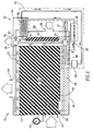
- a dehumidifying system 10 as described in the above referenced applications, comprises, as its two main sections a dehumidifying chamber 12 and a regenerator unit 32. Moist air enters dehumidifying chamber 12 via a moist air inlet 14 and dried air exits chamber 12 via a dry air outlet 16.
- desiccant 28 is pumped by a pump 20 from a desiccant reservoir 30 via a pipe 13 to a series of nozzles 22. These nozzles shower a fine spray of the desiccant into the interior of chamber 12, which is filled, for example, with a cellulose sponge material 24 such as is generally used in the art for such purposes.
- the desiccant is simply dripped on the sponge material. The desiccant slowly percolates downward through the sponge material into reservoir 30.
- Moist air entering the chamber via inlet 14 contacts the desiccant droplets. Since the desiccant is hygroscopic, it absorbs water vapor from the moist air and drier air is expelled through outlet 16.
- Reservoir 30 is generally located on the bottom of chamber 12 so that the desiccant from sponge 24 falls directly into the reservoir.
- a pump 35 and associated motor 37 pump desiccant from an extension of reservoir 30 into pipe 13.
- a divider 38 receives desiccant from pipe 13 and sends part of the desiccant to nozzles 22 and part to regenerator unit 32.
- a valve or constriction 39 (preferably a controllable valve or constriction) may be provided to control the proportion of the desiccant which is fed to regenerator 32. If a controllable valve or constriction is used, the amount of desiccant is optimally controlled in response to the amount of moisture in the desiccant.
- Chamber 34 includes a heat exchanger 36 which heats the desiccant to drive off part of the water vapor it has absorbed, thus regenerating it.
- Regenerated liquid desiccant is transferred back to reservoir 30 via a pipe 40 and a tube 42 of sponge material such as that which fills chamber 12.
- Tube 40 is shown as being contained in a chamber 58 which has an inlet 60 and an outlet 62.
- Air generally from outside the area in which the air is being modified, for example from an air conditioning exhaust, as described below, enters the chamber via inlet 60 and carries away additional moisture which is evaporated from the still hot desiccant in tube 42.
- the air exiting at outlet 62 carries away this moisture and also moisture which was removed from the desiccant in the regenerator.
- a fan (not shown) at exit 62 sucks air from chamber 58.
- heat is transferred from the regenerated liquid desiccant to the desiccant entering or in the regenerator by bringing the two desiccant streams into thermal (but not physical) contact in a thermal transfer station (not shown).
- a heat pump may be used to transfer additional energy from the cooler desiccant leaving the regenerator to the hotter desiccant entering the regenerator, such that the desiccant returning to the reservoir is actually cooler than the desiccant which enters chamber 58.
- a heat pump system 45 which extracts heat from the desiccant in reservoir 30 to provide energy to heat exchanger 36.
- this heat pump includes (in addition to exchanger 36 which is the condenser of the system) a second heat exchanger 46 in reservoir 30, which is the evaporator of the system, and an expansion valve 56.
- This transfer of energy results in a reduced temperature of the desiccant which contacts the air being dried thus reducing the temperature of the dried air.
- this transfer of energy reduces the overall requirement of energy for operating the regenerator, generally by up to a factor of 3. Since the energy utilized by the regeneration process is the major energy requirement for the system, this reduction in energy usage can have a major effect on the overall efficiency of the system.
- this method of heating of the desiccant in the regenerator may be supplemented by direct heating, utilizing a heating coil or waste heat from an associated air-conditioner.
- the proportion of water vapor in the desiccant in reservoir 30 and in the regenerated desiccant must generally be within certain limits, which limits depend on the particular desiccant used.
- a lower limit on the required moisture level is that needed to dissolve the desiccant such that the desiccant is in solution and does not crystallize.
- the moisture level is too high, the desiccant becomes inefficient in removing moisture from the air which enters chamber 12.
- some desiccants are liquid even in the absence of absorbed moisture. The moisture level in these desiccants need not be so closely controlled. However, even in these cases the regeneration process (which uses energy) should only be performed when the moisture level in the desiccant is above some level.
- This monitoring function is generally performed by measurement of the volume of desiccant, which increases with increasing moisture.
- a method of measuring the volume of liquid in the reservoir is by measurement of the pressure in an inverted vessel 50 which has its opening placed in the liquid in the reservoir.
- a tube 52 leads from vessel 50 to a pressure gauge 54.
- the pressure measured by gauge 52 increases. Since the volume of desiccant in the dehumidifier chamber and in the regenerator is fairly constant, this gives a good indication of the amount of desiccant and thus of the amount of moisture entrained in the desiccant.
- the heat in chamber 34 is turned on.
- the heater is turned off.
- heat pumps or other heat transfer means are provided to transfer heat from the dried air exiting chamber 12 and or from the heated moist air leaving regenerator chamber 34, to heat the desiccant on its way to or in chamber 34. If heat pumps are used, the source of the heat may be at a temperature lower than the desiccant to which it is transferred.
- cooling of the desiccant in the reservoir can result in dried air leaving the dehumidifier which has the same, or optionally a lower temperature than the moist air entering the dehumidifier, even prior to any additional optional cooling of the dry air. This feature is especially useful where the dehumidifier is used in hot climates in which the ambient temperature is already high.
- one of the problems with dehumidifier systems is the problem of determining the amount of water in the desiccant solution so that the dehumidifier solution water content may be kept in a proper range.
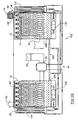
- a self regulating dehumidifier 100 that is self regulating with respect to water content of the desiccant solution and thus does not require any measurement of the volume or water content of the desiccant solution, is shown in Fig. 3A. Furthermore, the dehumidifier operates until a predetermined humidity is reached and then ceases to reduce the humidity, without any controls or cut-offs.
- Dehumidifier 100 is similar to dehumidifier 10 of Fig. 2, with several significant differences.
- the system does not require any measurement of water content and thus does not have a volumetric measure for the desiccant. However, such a measurement may be provided as a safety measure if the solution becomes too concentrated.
- the heat pump transfers heat between two streams of desiccant solution being transferred from reservoir 30 (which is conveniently divided into two portions 30A and 30B connected by pipes 30C), namely a first stream being pumped to nozzles 22 by a pump system 130, via a conduit 102 and a second stream being pumped to regenerator unit 32 by a pump system 132, via a conduit 104.
- pipes 30C are designed so that its major effect is to generate a common level of the solution in portions 30A and 30B.
- the two reservoir portions have different temperatures. This necessarily results in different concentrations of desiccant.
- a temperature differential of 5°C or more is maintained, optionally, 10°C or more or 15°C or even more.
- reservoir portion 30A is at a temperature of 30°C or more and reservoir portion 30B is at a temperature of 15°C or less.
- regenerator unit 32 In Fig. 3A, a different construction for regenerator unit 32 is shown, which is similar to that of the dehumidifier section. Furthermore, in Fig. 3A, neither section has a cellulose sponge material. Such material may be added to the embodiment of Fig. 3A or it may be omitted from the embodiment of Fig. 2 and replaced by the spray mechanism of Fig. 3A.
- spray nozzles are not used. Rather, the spray nozzles are replaced by a dripper system from which liquid is dripped on the cellulose sponge to continuously wet the sponge. Such systems are shown, for example in the above referenced PCT/IL98/00552.
- heat pump system 45 extracts heat from the desiccant solution in conduit 102 and transfers it to the desiccant in conduit 104.
- Heat pump system 45 contains, in addition to the components contained in the embodiment of Fig. 2, an optional heat exchanger 136 to transfer some of the heat from the refrigerant leaving heat exchanger 104 to the regenerating air.
- the compressor is also cooled by the regenerating air.
- additional air not used in the regenerator, may be used for cooling the compressor and the refrigerant. Alternatively, only such air is used for such cooling.
- Cooling the refrigerant and/or compressor in this manner results in the removal of additional air from the system, which allows the refrigerant system to operate at a lower temperature. Operating the system without such additional cooling, may result in the refrigerant being too hot in the steady state to operate properly.
- Heat pump 45 is set to transfer a fixed amount of heat.
- the humidity set point is determined by controlling the amount of heat transferred between the two streams.
- regenerator is set up, such that at this same temperature and humidity, it removes the same amount of water from the desiccant solution. This may require an input of heat (additionally to the heat available from the heat pump).
- the air entering the dehumidifier chamber has a lower humidity, for example 80%.
- a lower humidity for example 80%.
- less liquid is removed (since the efficiency of water removal depends on the humidity) and thus, the temperature of the desiccant solution leaving the dehumidifier chamber also drops.
- the amount of water removed from the solution in the regenerator also drops. This results in a new balance with less water removed and the desiccant solution at a lower temperature.
- a lower temperature desiccant results in cooler air.
- the temperature of the exiting air is also reduced.
- the relative humidity remains substantially the same. It should be understood that a reduction of input air temperature has substantially the same effect.
- the system is self regulating, with the dehumidifying action cutting off at some humidity level.
- the humidity level at which this takes place will depend on the capacity of the solution sprayed from nozzles 22 to absorb moisture and the ability of the solution and on the capacity of the solution sprayed from nozzles 22' to release moisture.
- the dehumidifier becomes less able to remove moisture from it.
- the solution is cooled on each transit through the conduit 102 and the percentage of desiccant in the solution in 30B reaches some level.
- the solution in 30A becomes more concentrated and less moisture is removed from it (all that happens is that it gets heated).
- both removal and absorption of moisture by the solution stop since the respective solutions entering the dehumidifier and regenerator chambers are in stability with the air to which or from which moisture is normally transferred.
- this humidity point can be adjusted by changing the amount of heat transferred between the solutions in conduits 102 and 104. If greater heat is transferred, the desiccant in the dehumidifying chamber is cooler and the desiccant in the regeneration chamber is hotter. This improves the moisture transfer ability of both the dehumidifying chamber and the regenerator and the humidity balance point is lowered. For less heat pumped from the dehumidifier side to the regenerator side, a higher humidity will result. In addition, the set-point will depend somewhat on the relative humidity of the air entering the regenerator.
- the device of Fig. 3B can be used.
- the device of Fig. 3B is the same as the device of Fig. 3A, except that heat exchanger 136 at the input of the regenerator is moved to the output of the dehumidifier and denoted 136'.
- the device shown in Fig. 3B produces dehumidified, warmed air.
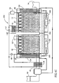
- Figs. 4A and 4B show another dehumidifier 200, in which no pumping of desiccant is required. Except as described below, it is generally similar to the dehumidifiers of Fig. 3A and 3B, except that there is no pumping of the desiccant liquid between the sumps 30A and 30B. (Figs. 4A and 4B do have a somewhat different layout from those of Figs. 3A and 3B.) The inventors have surprisingly found that an appropriately shaped and sized aperture, such as aperture 202 connecting the two sumps provides a suitable way to provide required transfer between the two sumps.
- sump 30B (the sump of dehumidifying chamber 12) accumulates additional moisture over sump 30A (the sump of regenerator 32). This additional moisture must be transferred to sump 30A or directly to the regenerator in order to remove the moisture from the desiccant.
- concentration of desiccant in sump 30B is much lower than that in sump 30A, and the proportion of desiccant in sump 30A must be continually increased so that the efficiency and drying capacity of regeneration is kept high.
- sumps are kept separate and pumps are used to pump the liquid from one sump to the other. This allows for a temperature differential to be maintained between the sumps and thus between the regenerator and the dehumidifying sections.
- pipe 30C is so constructed that only minimal liquid transfer takes place between the sumps, preserving a relatively high temperature differential.
- the apparatus of Figs. 4A and 4B solves this problem by transferring the desiccants and salts by diffusion between the liquids in the sumps, rather than by pumping desiccant solution between the sumps.
- desiccant salt ions are transferred from the regenerator sump to the pumps, and only moisture, on a net basis is transferred from the dehumidifier sump to the regenerator sump.
- aperture 202 is provided between sumps 30A and 30B.
- the size and positioning of this aperture is chosen to provide transfer of ions of water and desiccant salt between the sumps without an undesirable amount of thermal transfer, especially from the hotter to the cooler reservoir.
- the size of the aperture may be increased, such that at full dehumidification, the flow of heat between the sumps is at an acceptable level.
- Undesirable heat flow may be determined by measuring the temperature near the hole and comparing it to the temperature in the bulk solution in the sump.
- the hole is too large, there will generally be a significant thermal flow from sump 30B to sump 30A.
- the hole size is reduced too much, the transfer of ions is reduced and the overall efficiency is reduced.
- Figs. 4A and 4B may provide temperature differentials of the same order (or even greater) than those of Fig. 3A and 3B.
- the aperture is rectangular, with rounded corners having a width of 1-3 cm (preferably about 2 cm) and a height of 1-10 cm, depending on the capacity of the system.
- the hole is placed at the bottom of the partition between the reservoirs, so as to take advantage of the higher salt concentration in the regenerator reservoir at the bottom of the reservoir. The additional height allows the system to operate even under extreme conditions when some crystallization (which may block the aperture) occurs at the bottom of the reservoir.
- the aperture is defined by a series of heightwise distributed holes.
- the aperture is defined by a slit at the bottom and spaced holes above.
- the amount of diffusion of salt ions is dependent on the amount of liquid in the system which is, in turn, dependent on the humidity.
- the liquid increases and the flow of water and ions (by diffusion in the reverse direction) also increases.
- Figs. 4A and 4B Some points about the dehumidifier of Figs. 4A and 4B should be noted. There is a net flow of moisture, via aperture 202 from reservoir 30B to reservoir 30A when the system has reached a steady state and the air conditions are constant. In fact, since the dehumidifier section is continuously adding moisture to the desiccant and the regenerator is continuously removing moisture from it, this is to be expected. During operation, the concentration of ions in reservoir 30A is generally higher than that in reservoir 30B. This will be true, because the desiccant in 30A is continuously being concentrated and that in 30B is continuously be diluted. This difference in concentration causes a diffusive flow of ions from reservoir 30A to reservoir 30B, via aperture 202.
- the temperature of the desiccant in reservoir 30B is 15°C and the concentration is 25% by weight of salt.
- the salt used is lithium chloride, since this is a stable salt with relatively high desiccating capacity. Lithium bromide is an even better desiccant, but is less stable; it too can be used.
- Other usable salts include magnesium chloride, calcium chloride and sodium chloride.
- Other liquid desiccants, as known in the art may also be used.
- the temperature and concentrations for reservoir 30A is 40°C and 35%. It should be understood that the concentration in reservoir 30A can be higher (without crystallization) than that in reservoir 30B due to the higher temperature of the desiccant. When the system stops, the concentrations and temperatures soon equalize. Of course, these numbers will vary widely depending on the temperature and humidity of the air being conditioned and the "set point" of the dehumidifier (as determined by the heat pump setting), among other factors.
- Fig. 4C shows a system in which either the embodiment of Fig. 4A or 4B can be provided by switching valves 47 and 49 from open to closed states. For example, if valve 47 is open (i.e., it allows flow) and valve 49 is closed (no flow), the embodiment of Fig. 4A will result. If valve 47 is closed and valve 49 is open, the embodiment of Fig. 4B will result. Thus, if these valves are electrical or hydraulic, the apparatus shown in Fig. 4C can be easily switched between a cooling dehumidifier state and a heating dehumidifier state, both with high efficiency.
- Fig. 4C is shown only for the embodiment of Fig. 4. It should be understood that it can also be applied to the dehumidifier of Figs. 3A and 3B and also to that of Fig. 2. It should also be understood that the valve layout shown in Fig. 4C is exemplary only. A large number of different valve layouts could,be used for the switching of the path of the refrigerant in the manner shown in Fig. 4C.
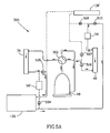
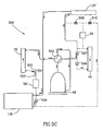
- Figs. 5A-5C show three states of a refrigerant system 500, in accordance with an embodiment of the invention. These figures show an alternative way of connecting the elements of the system of Fig. 4C to provide a system in which three states are available, namely, cooling and dehumidification, heating and dehumidification and heating and humidification. Figs. 5A-C do not show all of the elements of Fig. 4C, however, the common elements are indicated with identical reference numbers. Additional elements, as indicated below, are also shown.
- FIG. 4C and 5A-5C The basic building blocks of the refrigerant system that are common to Figs. 4C and 5A-5C are compressor 48, heat exchangers 136 and 136', heat exchangers 36 and 46 and expansion valve 56. Valves 49 and 47 and the refrigerant piping shown in Fig. 4C are replaced by the structure shown in Figs. 5A-5C. The rest of the system and the position of the above mentioned components in Fig. 4C need not be changed.
- Refrigerant system 500 comprises, in addition to the components shown in Fig. 4C, a series of pipes for refrigerant, a switch 502, a second expansion valve 56', four on-way valves 504-507 and two switchable stop valves 508 and 510.
- a switch 502 for refrigerant
- a second expansion valve 56' for refrigerant
- four on-way valves 504-507 for refrigerant
- two switchable stop valves 508 and 510 two switchable stop valves 508 and 510.
- the portions of the piping in which there is no flow are shown as dashed lines.
- the direction of flow is shown throughout. As in the above explanation, open indicates flow is allowed and closed indicates that it is not.
- Fig. 5A shows a configuration which is functionally the same as that shown in Fig. 4A.
- switch 508 is closed and switch 510 is open, so that there is no flow of refrigerant through heat exchanger 136' and refrigerant does flow through heat exchanger 136. This results in cooling and dehumidification of the air being conditioned, as described above.
- heat exchanger 46 is cold and heat is transferred therefrom to heat exchangers 36 and 136, which are hotter.
- Fig. 5B shows a second configuration which is functionally the same as that shown in Fig. 4B.
- switch 510 is closed and switch 511 is open, so that there is no flow of refrigerant through heat exchanger 136 and refrigerant does flow through heat exchanger 136'. This results in heating and dehumidification of the air being conditioned, as described above.
- heat exchanger 46 is cold and heat is transferred therefrom to heat exchangers 36 and 136', which are hotter.
- Fig. 5C the position of switch 502 is changed and both switches 508 and 510 are closed.
- refrigerant flows in line 520 and expansion valve is operative. There is no flow in heat exchanger 46.
- the refrigerant system then consists of heat exchangers 36, 136 and 136'.
- the conditioned air is passed through the "dehumidifying chamber" 12. However, in the absence of cooling of this chamber, moisture is added to the air rather than removed from it.
- the moisturized air passes though heat exchanger 136' so that heated humidified air results.
- Heat exchanger 36 acts to cool the desiccant in the "regenerator" 32 so that it absorbs moisture from the outside air.
- Fig. 6 shows a diagram, similar to that of Fig. 1, except that the desiccant systems of Figs. 2-4 are represented by a line 3.
- Fig. 6 shows that the cooling of the desiccant in the dehumidifier side, by the heat pump, results in only a small change in the temperature of the air.
- the air treated by the dehumidifier need neither be cooled by the air conditioner (as in the case of the desiccant systems of the prior art) nor need it be heated as is necessary if air conditioning systems are used to remove the moisture.
- Fig. 7 shows a structure 1000 useful for the control of the amount of dehumidification.
- the level of liquid in the system is reduced, at steady state, over that in high humidity situations.
- the structure of Fig. 7 is useful in providing automatic control to achieve these ends.
- Fig, 7 is similar to Fig. 4C, except that a sponge-like material (as in Fig. 2), replaces the spray shown in Fig. 4C, for the regenerator.
- a sponge-like material as in Fig. 2
- a partition 1002 is provided to direct the incoming air to the desiccant when the liquid desiccant level is high. As the desiccant level falls below the bottom edge of the partition, air bypasses the sponge and passes through passage 1004, due to the much lower impedance of passage 1004. Thus, the dehumidifying action is reduced when it is not required.
- the amount of water removed from the system is increased when the liquid level is high (high ambient humidity) and reduced when it is not.
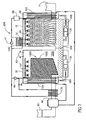
- Fig. 8 is a block diagram of a combined dehumidifier/air-conditioner system 310 in the context of a split air conditioner 312, such as is normally used to cool an enclosed area such as a large room 314 in a house.
- Air conditioner 312 in its simplest form, comprises a room air inlet 316 which feeds room air via a conduit 318 to an evaporator 320 which cools the air. Air from the room is drawn into evaporator 320 by a fan 322 and exists the evaporator via a room air outlet 324 to room 314.
- Heated refrigerant is compressed by a compressor 324 (shown in an outside portion of air conditioner 312) and passed to a condenser 328.
- Condenser 328 is cooled by outside air drawn into a cooling inlet 330 by a fan 332. Heated air exits outside portion 326 via a waste heat outlet 334.
- the cooled compressed refrigerant is expanded in an expander 336 and returns to evaporator 320 to be used to cool the room air.
- air conditioner 312 comprises a fresh air inlet 338 through which fresh air is brought in to the room.
- the quantity of fresh air is generally controlled by a louver or baffle system 340, 341. Either one or both louvers or baffles 340, 341 may be supplied, depending on the amount and type of control over the proportion of fresh air required.
- the fresh air is mixed with the air drawn from the room and is fed to evaporator 320.
- Air conditioner 312, as described, is completely conventional in design. In some embodiments of the invention, other types of air conditioning systems may be used as appropriate.
- a dehumidifier unit 342 is utilized to increase the efficiency and cooling capacity of the air-conditioner.
- Dehumidifier 342 in a simplified block diagram comprises a drying unit 344 which receives outside air via a wet air inlet 346 and passes dried air out of a dried air outlet 348.
- the air is dried in unit 344 by passing it through a mist, or the like, of liquid desiccant or desiccant solution. Moisture in the air is adsorbed by the desiccant.
- dried air outlet 348 communicates with fresh air inlet 338 of air conditioner 312, for example, via a conduit 349. Since the impedance of drying unit is relatively low, no air pump, additional to fan 322 of the air conditioner is generally required. However, one may be provided, in some embodiments of the invention.
- Desiccant with adsorbed water is transferred to a regenerator 350 in which the desiccant is regenerated by removing moisture from it, by heating the desiccant.
- this heating and the carrying away of the water vapor removed from the desiccant is accomplished by passing hot air through the desiccant (optionally, the desiccant is in a mist or other finely divided form).
- the hot relatively dry air enters the dehumidifier via an inlet 352 and exits via an outlet 354.
- This hot air is conveniently and efficiently provided, in accordance with an embodiment of the invention, by connecting waste heat outlet 334 of air conditioner 312 with inlet 352 of the dehumidifier. Since the pressure drop in regenerator 350 is very low, optionally, no fan or other air pump in addition to fan 332 of air conditioner 312 is needed to move the air through the regenerator.
- the air conditioner and dehumidifier share a common control panel from which both are controlled and from which, optionally, all the above functions can be turned on or off or adjusted.
- one of the systems of Figs. 1-4 is used as dehumidifier 342.
- port 348 of Fig. 4 corresponds to port 16 of Figs. 1-4
- port 352 corresponds to port 60
- port 346 corresponds to port 14
- port 354 corresponds to port 62.
- dehumidifier 342 is shown in very schematic form in Fig. 7 and that, for example, the placement of the elements may be different and many elements are not shown in Fig. 4.
- the pumps shown in Fig. 7 are not present.
- the heat-pumps of Figs. 1-4 are not shown in Fig. 4, although they are preferably present in the system.
- dehumidifier 342 can be an add on to air conditioner 312, which may be a standard unit.
- the task of drying incoming air, performed in a most inefficient manner by the air conditioner, has been transferred to a more efficient dehumidifier which utilizes waste heat from the air conditioner for most of its energy (only energy to pump the desiccant between dryer 344 and regenerator 350 is needed).
- the capacity of the air conditioner system for cooling is enhanced since it no longer needs to dry the air.
- the efficiency of the combined unit actually increases with increasing temperature in contrast to normal air conditioner systems.
- the dehumidifier While the heat available is the heat developed by the air conditioner in cooling all of the air, the dehumidifier dries only part of the air, namely that entering the room. This balance means that the heating requirements for the dehumidifier are generally easily met by the air conditioner exhaust.
- a combination device such as that described above, has shown a 60% cooling capacity over the air conditioner by itself and a 30% efficiency improvement over the use of an air conditioner by itself, for the same indoor air quality.
- the heat is removed from liquid desiccant in the sump.
- it could be removed from liquid desiccant being transported to the drying chamber.
- the heat is pumped from liquid desiccant while it is being transported to the drying chamber.
- it could be removed from the liquid desiccant in a sump that receives carrier liquid from the drying chamber.
- one or both of the refrigerant/desiccant heat exchangers is in the dehumidifying or regenerating chambers.
- Fig. 2 shows a different type of regenerator than does Figs. 3 and 4.
- the regenerator types are interchangeable.
- Fig. 2 shows the heat being transferred by the heat pump to the liquid in the regeneration chamber. Alternatively, or additionally, it can be transferred to liquid desiccant being transported to the regeneration chamber (as in Figs. 3 and 4). Finally, while not shown in the Figs., the heat could be transferred to liquid in sump 30A for all both Figs 3 and 4.
Landscapes
- Engineering & Computer Science (AREA)
- Chemical & Material Sciences (AREA)
- Combustion & Propulsion (AREA)
- Mechanical Engineering (AREA)
- General Engineering & Computer Science (AREA)
- Life Sciences & Earth Sciences (AREA)
- Sustainable Development (AREA)
- Central Air Conditioning (AREA)
- Drying Of Gases (AREA)
Applications Claiming Priority (3)
| Application Number | Priority Date | Filing Date | Title |
|---|---|---|---|
| IL14157901A IL141579A0 (en) | 2001-02-21 | 2001-02-21 | Dehumidifier/air-conditioning system |
| IL14157901 | 2001-02-21 | ||
| PCT/IL2001/000373 WO2002066901A1 (en) | 2000-05-15 | 2001-04-23 | Dehumidifier/air-conditioning system |
Publications (2)
| Publication Number | Publication Date |
|---|---|
| EP1364168A1 EP1364168A1 (en) | 2003-11-26 |
| EP1364168B1 true EP1364168B1 (en) | 2007-02-21 |
Family
ID=11075160
Family Applications (1)
| Application Number | Title | Priority Date | Filing Date |
|---|---|---|---|
| EP01925841A Expired - Lifetime EP1364168B1 (en) | 2001-02-21 | 2001-04-23 | Dehumidifier/air-conditioning system |
Country Status (13)
| Country | Link |
|---|---|
| US (1) | US6976365B2 (enExample) |
| EP (1) | EP1364168B1 (enExample) |
| JP (3) | JP4923207B2 (enExample) |
| CN (1) | CN100366981C (enExample) |
| AR (1) | AR035686A1 (enExample) |
| AT (1) | ATE354770T1 (enExample) |
| AU (1) | AU2001252516B2 (enExample) |
| DE (1) | DE60126834T2 (enExample) |
| ES (1) | ES2282249T3 (enExample) |
| IL (1) | IL141579A0 (enExample) |
| MX (1) | MXPA03007476A (enExample) |
| NZ (1) | NZ528336A (enExample) |
| WO (1) | WO2002066901A1 (enExample) |
Families Citing this family (99)
| Publication number | Priority date | Publication date | Assignee | Title |
|---|---|---|---|---|
| US7905107B2 (en) | 2001-12-27 | 2011-03-15 | DUCool | High efficiency dehumidifiers and combine dehumidifying/air-conditioning systems |
| US20050109052A1 (en) * | 2003-09-30 | 2005-05-26 | Albers Walter F. | Systems and methods for conditioning air and transferring heat and mass between airflows |
| WO2005062831A2 (en) * | 2003-12-21 | 2005-07-14 | Albers Walter F | Migro-cycle energy transfer systems and methods |
| KR100829678B1 (ko) * | 2004-03-31 | 2008-05-16 | 다이킨 고교 가부시키가이샤 | 조습 장치 |
| US8302425B2 (en) * | 2004-05-11 | 2012-11-06 | Cyclect Singapore Pte Ltd. | Regenerative adsorption system with a spray nozzle for producing adsorbate vapor and condensing desorbed vapor |
| US20060042290A1 (en) * | 2004-09-01 | 2006-03-02 | Dai Xue Q | Split-type room air conditioner |
| US20090211276A1 (en) * | 2005-03-25 | 2009-08-27 | Dan Forkosh | System and method for managing water content in a fluid |
| JP3864982B2 (ja) * | 2005-05-30 | 2007-01-10 | ダイキン工業株式会社 | 空調システム |
| AU2006322970B2 (en) * | 2005-12-07 | 2011-06-30 | Ducool Ltd. | System and method for managing water content in a fluid |
| CN100451468C (zh) * | 2006-06-15 | 2009-01-14 | 清华大学 | 一种热泵驱动的多级溶液除湿和再生新风机组 |
| WO2008078194A2 (en) * | 2006-06-20 | 2008-07-03 | Adir Segal, Ltd. | Thermal load management system |
| CN100416169C (zh) * | 2006-08-11 | 2008-09-03 | 重庆大学 | 一种除湿溶液的再生装置 |
| CN100416170C (zh) * | 2006-08-11 | 2008-09-03 | 重庆大学 | 一种带有溶液除湿装置的空调系统 |
| TWI404897B (zh) * | 2006-08-25 | 2013-08-11 | Ducool Ltd | 用以管理流體中之水含量的系統及方法 |
| US20080256970A1 (en) * | 2006-09-19 | 2008-10-23 | Zhihan Huang | More energy efficient cooling system by utilizing defrosting water |
| US7658084B2 (en) * | 2007-04-03 | 2010-02-09 | Delphi Technologies, Inc. | Evaporative cooler |
| US8151579B2 (en) | 2007-09-07 | 2012-04-10 | Duncan Scot M | Cooling recovery system and method |
| CN101828078A (zh) * | 2007-09-14 | 2010-09-08 | 约翰·弗朗西斯·乌尔驰 | 空调装置 |
| US8268060B2 (en) * | 2007-10-15 | 2012-09-18 | Green Comfort Systems, Inc. | Dehumidifier system |
| WO2009094032A1 (en) | 2008-01-25 | 2009-07-30 | Midwest Research Institute | Indirect evaporative cooler using membrane-contained, liquid desiccant for dehumidification |
| US8627674B2 (en) * | 2008-05-15 | 2014-01-14 | Mark PLATT | Modular outboard heat exchanger air conditioning system |
| JP4384699B2 (ja) | 2008-05-22 | 2009-12-16 | ダイナエアー株式会社 | 調湿装置 |
| JP4374393B1 (ja) | 2008-05-27 | 2009-12-02 | ダイナエアー株式会社 | 調湿装置 |
| US20100090356A1 (en) * | 2008-10-10 | 2010-04-15 | Ldworks, Llc | Liquid desiccant dehumidifier |
| US9130503B2 (en) | 2009-05-08 | 2015-09-08 | 7Ac Technologies, Inc. | Solar energy systems |
| JP4536147B1 (ja) * | 2009-09-15 | 2010-09-01 | ダイナエアー株式会社 | 調湿装置 |
| CN101706136B (zh) * | 2009-11-21 | 2012-04-18 | 青岛大学 | 一种溶液调温调湿空气处理系统 |
| US10260761B2 (en) | 2010-05-18 | 2019-04-16 | Energy & Environmental Research Center Foundation | Heat dissipation systems with hygroscopic working fluid |
| US10808948B2 (en) | 2010-05-18 | 2020-10-20 | Energy & Environmental Research Center | Heat dissipation systems with hygroscopic working fluid |
| US10845067B2 (en) | 2010-05-18 | 2020-11-24 | Energy & Enviornmental Research Center | Hygroscopic cooling tower for waste water disposal |
| US9377207B2 (en) | 2010-05-25 | 2016-06-28 | 7Ac Technologies, Inc. | Water recovery methods and systems |
| CA3046529C (en) | 2010-06-24 | 2023-01-31 | University Of Saskatchewan | Liquid-to-air membrane energy exchanger |
| US8474277B2 (en) | 2010-07-13 | 2013-07-02 | General Electric Company | Compressor waste heat driven cooling system |
| US8584479B2 (en) * | 2010-08-05 | 2013-11-19 | Sanyo Electric Co., Ltd. | Air conditioner having a desiccant rotor with moisture adsorbing area |
| US8875526B1 (en) | 2010-08-09 | 2014-11-04 | Roland H. Isaacson | Temperature and humidity air treatment system |
| SG190387A1 (en) | 2010-11-23 | 2013-06-28 | Ducool Ltd | Air conditioning system |
| EP2652410A1 (en) * | 2010-12-13 | 2013-10-23 | Ducool, Ltd. | Method and apparatus for conditioning air |
| US8915092B2 (en) | 2011-01-19 | 2014-12-23 | Venmar Ces, Inc. | Heat pump system having a pre-processing module |
| US9810439B2 (en) | 2011-09-02 | 2017-11-07 | Nortek Air Solutions Canada, Inc. | Energy exchange system for conditioning air in an enclosed structure |
| JP5327372B2 (ja) * | 2011-09-16 | 2013-10-30 | ダイキン工業株式会社 | 調湿装置 |
| US20130186117A1 (en) * | 2012-01-20 | 2013-07-25 | General Electric Company | System and method to process inlet air |
| ES2755800T3 (es) | 2012-06-11 | 2020-04-23 | 7Ac Tech Inc | Métodos y sistemas para intercambiadores de calor turbulentos y resistentes a la corrosión |
| US9816760B2 (en) | 2012-08-24 | 2017-11-14 | Nortek Air Solutions Canada, Inc. | Liquid panel assembly |
| ES2407906B1 (es) * | 2012-11-08 | 2014-02-06 | Luis Felipe MAZO SANFÉLIZ | Sistema de tratamiento de aire |
| WO2014089164A1 (en) | 2012-12-04 | 2014-06-12 | 7Ac Technologies, Inc. | Methods and systems for cooling buildings with large heat loads using desiccant chillers |
| US9631848B2 (en) | 2013-03-01 | 2017-04-25 | 7Ac Technologies, Inc. | Desiccant air conditioning systems with conditioner and regenerator heat transfer fluid loops |
| US9267696B2 (en) * | 2013-03-04 | 2016-02-23 | Carrier Corporation | Integrated membrane dehumidification system |
| US9140460B2 (en) * | 2013-03-13 | 2015-09-22 | Alliance For Sustainable Energy, Llc | Control methods and systems for indirect evaporative coolers |
| US9140471B2 (en) * | 2013-03-13 | 2015-09-22 | Alliance For Sustainable Energy, Llc | Indirect evaporative coolers with enhanced heat transfer |
| US9109808B2 (en) * | 2013-03-13 | 2015-08-18 | Venmar Ces, Inc. | Variable desiccant control energy exchange system and method |
| US9772124B2 (en) | 2013-03-13 | 2017-09-26 | Nortek Air Solutions Canada, Inc. | Heat pump defrosting system and method |
| EP2972009B1 (en) * | 2013-03-14 | 2019-09-18 | 7AC Technologies, Inc. | Split liquid desiccant air conditioning system |
| KR20150119345A (ko) * | 2013-03-14 | 2015-10-23 | 7에이씨 테크놀로지스, 아이엔씨. | 액체 흡수제 공조 시스템 개장을 위한 방법 및 시스템 |
| US10352628B2 (en) | 2013-03-14 | 2019-07-16 | Nortek Air Solutions Canada, Inc. | Membrane-integrated energy exchange assembly |
| US10584884B2 (en) | 2013-03-15 | 2020-03-10 | Nortek Air Solutions Canada, Inc. | Control system and method for a liquid desiccant air delivery system |
| US11408681B2 (en) | 2013-03-15 | 2022-08-09 | Nortek Air Solations Canada, Iac. | Evaporative cooling system with liquid-to-air membrane energy exchanger |
| CN103225855B (zh) * | 2013-04-09 | 2015-09-30 | 清华大学 | 一种多级热泵循环驱动的溶液除湿空气处理装置 |
| US9470426B2 (en) | 2013-06-12 | 2016-10-18 | 7Ac Technologies, Inc. | In-ceiling liquid desiccant air conditioning system |
| EP3060856B1 (en) * | 2013-10-25 | 2022-11-23 | AIL Research Inc. | Methods for enhancing the dehumidification of heat pumps |
| KR102391093B1 (ko) * | 2014-03-20 | 2022-04-27 | 에머슨 클리메이트 테크놀로지즈 인코퍼레이티드 | 옥상 액체 데시컨트 시스템 및 방법 |
| DK3183051T3 (da) | 2014-08-19 | 2020-06-02 | Nortek Air Solutions Canada Inc | Væske-til-luftmembranenergivekslere |
| KR20170086496A (ko) * | 2014-11-21 | 2017-07-26 | 7에이씨 테크놀로지스, 아이엔씨. | 미니-스플릿 액체 데시컨트 공기 조화를 위한 방법 및 시스템 |
| CN104792103B (zh) * | 2015-04-03 | 2018-05-29 | 青岛海尔股份有限公司 | 干燥装置、冰箱及干燥剂恢复方法 |
| CN104801157A (zh) * | 2015-04-08 | 2015-07-29 | 上海理工大学 | 除湿装置及空气压缩机系统 |
| EP3985322B1 (en) | 2015-05-15 | 2024-11-06 | Nortek Air Solutions Canada, Inc. | Air conditioning system with a liquid to air membrane energy exchanger |
| US11092349B2 (en) | 2015-05-15 | 2021-08-17 | Nortek Air Solutions Canada, Inc. | Systems and methods for providing cooling to a heat load |
| US10962252B2 (en) | 2015-06-26 | 2021-03-30 | Nortek Air Solutions Canada, Inc. | Three-fluid liquid to air membrane energy exchanger |
| CN109073265B (zh) | 2016-03-08 | 2021-09-28 | 北狄空气应对加拿大公司 | 用于向热负载提供冷却的系统和方法 |
| GB2548590A (en) * | 2016-03-22 | 2017-09-27 | Gulf Organisation For Res And Dev | Smart cooling system for all climates |
| SG11201811354YA (en) * | 2016-06-19 | 2019-01-30 | Abe M Sher | Method apparatuses assemblies and systems for dehumidifying air and producing water |
| WO2018191805A1 (en) | 2017-04-18 | 2018-10-25 | Nortek Air Solutions Canada, Inc. | Systems and methods for managing conditions in enclosed space |
| EP3612771B1 (en) | 2017-04-18 | 2023-03-22 | Nortek Air Solutions Canada, Inc. | Desiccant enhanced evaporative cooling systems and methods |
| CN106931553A (zh) * | 2017-04-28 | 2017-07-07 | 北京格瑞高科科技股份有限公司 | 新型预冷式溶液调湿新风机组 |
| KR101986372B1 (ko) * | 2017-05-10 | 2019-09-30 | 장경필 | 조습용액을 이용한 습도 조절장치 |
| US10921001B2 (en) | 2017-11-01 | 2021-02-16 | 7Ac Technologies, Inc. | Methods and apparatus for uniform distribution of liquid desiccant in membrane modules in liquid desiccant air-conditioning systems |
| US10941948B2 (en) | 2017-11-01 | 2021-03-09 | 7Ac Technologies, Inc. | Tank system for liquid desiccant air conditioning system |
| JP6955582B2 (ja) * | 2018-01-04 | 2021-10-27 | シャープ株式会社 | 調湿装置および調湿方法 |
| US11662106B2 (en) | 2018-02-23 | 2023-05-30 | Scot M. Duncan | High efficiency dehumidification system and method |
| US11333372B2 (en) | 2018-03-09 | 2022-05-17 | Scot Matthew Duncan | Energy recovery high efficiency dehumidification system |
| WO2019202927A1 (ja) * | 2018-04-16 | 2019-10-24 | シャープ株式会社 | 空調装置 |
| US11022330B2 (en) | 2018-05-18 | 2021-06-01 | Emerson Climate Technologies, Inc. | Three-way heat exchangers for liquid desiccant air-conditioning systems and methods of manufacture |
| CA3107904A1 (en) | 2018-07-30 | 2020-02-06 | King Abdullah University Of Science And Technology | Liquid desiccant based humidity pump, evaporative cooler, and air purification systems |
| MX2021001137A (es) * | 2018-07-31 | 2021-06-15 | Univ King Abdullah Sci & Tech | Sistema y metodo de enfriador de desecante liquido. |
| US11679339B2 (en) * | 2018-08-02 | 2023-06-20 | Plug Power Inc. | High-output atmospheric water generator |
| CN109084427B (zh) * | 2018-08-15 | 2020-06-23 | 广东美的制冷设备有限公司 | 空调器的控制方法、装置、空调器及计算机可读存储介质 |
| WO2020059284A1 (ja) * | 2018-09-18 | 2020-03-26 | シャープ株式会社 | 調湿システム |
| US20210315169A1 (en) * | 2018-10-08 | 2021-10-14 | Mjnn Llc | Control of latent and sensible loads in controlled-environment agriculture and related lighting systems |
| US11117090B2 (en) | 2018-11-26 | 2021-09-14 | Palo Alto Research Center Incorporated | Electrodialytic liquid desiccant dehumidifying system |
| KR102041255B1 (ko) * | 2019-03-04 | 2019-11-07 | 아산엔텍 주식회사 | 올인원 습식 공기청정조화 장치 |
| CN109974146B (zh) * | 2019-03-19 | 2021-02-26 | 东南大学 | 针对冷库穿堂除湿的溶液除湿系统及运行方法 |
| JPWO2020209317A1 (ja) * | 2019-04-10 | 2021-12-23 | シャープ株式会社 | 調湿装置 |
| US11610158B2 (en) | 2019-05-02 | 2023-03-21 | Mjnn Llc | Automated placement of plant varieties for optimum performance within a grow space subject to environmental condition variability |
| JP7453890B2 (ja) * | 2020-10-05 | 2024-03-21 | 株式会社神戸製鋼所 | 再生装置、ガス処理装置、再生方法及びガス処理方法 |
| US12085293B2 (en) | 2021-03-17 | 2024-09-10 | Mojave Energy Systems, Inc. | Staged regenerated liquid desiccant dehumidification systems |
| GB2594617B (en) * | 2021-06-18 | 2022-04-13 | Gulf Organisation For Res And Development | Air treatment system |
| US11944934B2 (en) | 2021-12-22 | 2024-04-02 | Mojave Energy Systems, Inc. | Electrochemically regenerated liquid desiccant dehumidification system using a secondary heat pump |
| KR102532056B1 (ko) * | 2022-04-05 | 2023-05-16 | 엔트 주식회사 | 액체식 올인원 냉·난방 공기청정조화 장치 |
| JP2025539498A (ja) | 2022-12-12 | 2025-12-05 | モハベ エネルギー システムズ,インコーポレイテッド | 液体乾燥剤空調システム及び制御方法 |
| CN121038880A (zh) | 2023-04-07 | 2025-11-28 | 莫哈维能源系统公司 | 超低流量干燥剂空气调节系统装置和方法 |
Family Cites Families (63)
| Publication number | Priority date | Publication date | Assignee | Title |
|---|---|---|---|---|
| US2218407A (en) | 1937-08-25 | 1940-10-15 | E A Lab Inc | Air conditioner |
| US2690656A (en) * | 1949-03-24 | 1954-10-05 | Cummings William Warren | Method of air conditioning |
| US2672024A (en) | 1951-01-12 | 1954-03-16 | Carrier Corp | Air conditioning system employing a hygroscopic medium |
| US2798570A (en) | 1956-02-20 | 1957-07-09 | Surface Combustion Corp | Air conditioning |
| US2952993A (en) | 1957-12-13 | 1960-09-20 | Carrier Corp | Air conditioner |
| US3264840A (en) * | 1965-05-03 | 1966-08-09 | Westinghouse Electric Corp | Air conditioning systems with reheat coils |
| US3311355A (en) | 1965-08-19 | 1967-03-28 | Joseph M Rait | Portable humidity control device |
| US4270362A (en) * | 1977-04-29 | 1981-06-02 | Liebert Corporation | Control system for an air conditioning system having supplementary, ambient derived cooling |
| US4180985A (en) | 1977-12-01 | 1980-01-01 | Northrup, Incorporated | Air conditioning system with regeneratable desiccant bed |
| US4259849A (en) | 1979-02-15 | 1981-04-07 | Midland-Ross Corporation | Chemical dehumidification system which utilizes a refrigeration unit for supplying energy to the system |
| US4373347A (en) | 1981-04-02 | 1983-02-15 | Board Of Regents, University Of Texas System | Hybrid double-absorption cooling system |
| US4635446A (en) | 1981-05-15 | 1987-01-13 | Camp Dresser & Mckee | Dehumidification apparatus |
| US4430864A (en) | 1981-12-31 | 1984-02-14 | Midwest Research Institute | Hybrid vapor compression and desiccant air conditioning system |
| IL64915A (en) | 1982-02-02 | 1985-04-30 | Joel Harband | Apparatus and method for temperature and humidity control |
| US4723417A (en) | 1985-08-05 | 1988-02-09 | Camp Dresser And Mckee Inc. | Dehumidification apparatus |
| US4685617A (en) | 1985-08-06 | 1987-08-11 | Geophysical Engineering Company | Method of and apparatus for conditioning air in enclosures |
| CA1305857C (en) | 1985-09-26 | 1992-08-04 | Gad Assaf | Method of and means for controlling the condition of air in an enclosure |
| US4700550A (en) | 1986-03-10 | 1987-10-20 | Rhodes Barry V | Enthalpic heat pump desiccant air conditioning system |
| US4987750A (en) | 1986-07-08 | 1991-01-29 | Gershon Meckler | Air conditioning apparatus |
| US4819444A (en) | 1986-07-08 | 1989-04-11 | Manville Sales Corporation | Air conditioning apparatus |
| US4691530A (en) | 1986-09-05 | 1987-09-08 | Milton Meckler | Cogeneration and central regeneration multi-contactor air conditioning system |
| JPH0544677Y2 (enExample) * | 1987-05-15 | 1993-11-12 | ||
| US4910971A (en) | 1988-02-05 | 1990-03-27 | Hydro Thermal Engineering Pty. Ltd. | Indirect air conditioning system |
| JPH02157553A (ja) * | 1988-12-09 | 1990-06-18 | Taikisha Ltd | 放射冷房装置 |
| US5197299A (en) | 1988-12-17 | 1993-03-30 | Samsung Electronics Co., Ltd. | Window-type air conditioner |
| US4905479A (en) | 1989-01-27 | 1990-03-06 | Gas Research Institute | Hybrid air conditioning system |
| US4955205A (en) | 1989-01-27 | 1990-09-11 | Gas Research Institute | Method of conditioning building air |
| US4887438A (en) | 1989-02-27 | 1989-12-19 | Milton Meckler | Desiccant assisted air conditioner |
| CA2015839A1 (en) | 1989-05-11 | 1990-11-11 | Gad Assaf | Method of and apparatus for reducing the heat load on a greenhouse |
| US4939906A (en) | 1989-06-09 | 1990-07-10 | Gas Research Institute | Multi-stage boiler/regenerator for liquid desiccant dehumidifiers |
| US4941324A (en) | 1989-09-12 | 1990-07-17 | Peterson John L | Hybrid vapor-compression/liquid desiccant air conditioner |
| US4984434A (en) * | 1989-09-12 | 1991-01-15 | Peterson John L | Hybrid vapor-compression/liquid desiccant air conditioner |
| SU1690827A2 (ru) * | 1989-11-03 | 1991-11-15 | Воронежский инженерно-строительный институт | Абсорбционное устройство дл осушени газа |
| US5070703A (en) | 1990-02-06 | 1991-12-10 | Battelle Memorial Institute | Hybrid air conditioning system integration |
| US5058394A (en) | 1990-02-06 | 1991-10-22 | Battelle Memorial Institute | Hybrid air conditioning system subsystem integration |
| US5020334A (en) | 1990-02-23 | 1991-06-04 | Gas Research Institute | Localized air dehumidification system |
| US5022241A (en) | 1990-05-04 | 1991-06-11 | Gas Research Institute | Residential hybrid air conditioning system |
| GB2252738A (en) | 1991-02-14 | 1992-08-19 | Mountain Breeze Ltd | Dehumidifier |
| US5471852A (en) | 1991-07-05 | 1995-12-05 | Meckler; Milton | Polymer enhanced glycol desiccant heat-pipe air dehumidifier preconditioning system |
| US5297398A (en) | 1991-07-05 | 1994-03-29 | Milton Meckler | Polymer desiccant and system for dehumidified air conditioning |
| US5191771A (en) | 1991-07-05 | 1993-03-09 | Milton Meckler | Polymer desiccant and system for dehumidified air conditioning |
| US5213154A (en) | 1992-08-17 | 1993-05-25 | Gas Research Institute | Liquid desiccant regeneration system |
| US5351497A (en) | 1992-12-17 | 1994-10-04 | Gas Research Institute | Low-flow internally-cooled liquid-desiccant absorber |
| US5826641A (en) | 1994-10-27 | 1998-10-27 | Aaon, Inc. | Air conditioner with heat wheel |
| JPH08192022A (ja) * | 1995-01-12 | 1996-07-30 | Hitachi Metals Ltd | 吸収式調湿装置 |
| US6018954A (en) | 1995-04-20 | 2000-02-01 | Assaf; Gad | Heat pump system and method for air-conditioning |
| IL113446A (en) | 1995-04-20 | 1998-04-05 | Assaf Gad | Heat pump system and a method for air conditioning |
| US5661983A (en) | 1995-06-02 | 1997-09-02 | Energy International, Inc. | Fluidized bed desiccant cooling system |
| US5582025A (en) | 1995-06-21 | 1996-12-10 | Slant/Fin Corporation | Low obstruction window air conditioner |
| US5791153A (en) | 1995-11-09 | 1998-08-11 | La Roche Industries Inc. | High efficiency air conditioning system with humidity control |
| US5816065A (en) | 1996-01-12 | 1998-10-06 | Ebara Corporation | Desiccant assisted air conditioning system |
| US5950442A (en) | 1996-05-24 | 1999-09-14 | Ebara Corporation | Air conditioning system |
| MY117922A (en) | 1996-12-27 | 2004-08-30 | Ebara Corp | Air conditioning system |
| US6000684A (en) | 1997-06-24 | 1999-12-14 | Research Products Corporation | Evaporative wicking pad |
| IL122065A (en) | 1997-10-29 | 2000-12-06 | Agam Energy Systems Ltd | Heat pump/engine system and a method utilizing same |
| JPH11137948A (ja) | 1997-11-07 | 1999-05-25 | Daikin Ind Ltd | 除湿装置 |
| AU4963397A (en) * | 1997-11-16 | 1999-06-07 | Drykor Ltd. | Dehumidifier system |
| US6216483B1 (en) | 1997-12-04 | 2001-04-17 | Fedders Corporation | Liquid desiccant air conditioner |
| US6134903A (en) | 1997-12-04 | 2000-10-24 | Fedders Corporation | Portable liquid desiccant dehumidifier |
| US6138470A (en) | 1997-12-04 | 2000-10-31 | Fedders Corporation | Portable liquid desiccant dehumidifier |
| JPH11223359A (ja) * | 1998-02-10 | 1999-08-17 | Nippon Piimakku Kk | 住宅用一体型空調機 |
| US6189869B1 (en) | 1998-07-27 | 2001-02-20 | Emerson Electric Co. | Wick system for a humidifier |
| HK1045558A1 (zh) * | 1999-03-14 | 2002-11-29 | Drykor Ltd. | 除湿器/空调系统 |
-
2001
- 2001-02-21 IL IL14157901A patent/IL141579A0/xx active IP Right Grant
- 2001-04-23 NZ NZ528336A patent/NZ528336A/en not_active IP Right Cessation
- 2001-04-23 WO PCT/IL2001/000373 patent/WO2002066901A1/en not_active Ceased
- 2001-04-23 ES ES01925841T patent/ES2282249T3/es not_active Expired - Lifetime
- 2001-04-23 DE DE60126834T patent/DE60126834T2/de not_active Expired - Lifetime
- 2001-04-23 JP JP2002566180A patent/JP4923207B2/ja not_active Expired - Fee Related
- 2001-04-23 AU AU2001252516A patent/AU2001252516B2/en not_active Ceased
- 2001-04-23 US US10/468,658 patent/US6976365B2/en not_active Expired - Fee Related
- 2001-04-23 EP EP01925841A patent/EP1364168B1/en not_active Expired - Lifetime
- 2001-04-23 MX MXPA03007476A patent/MXPA03007476A/es unknown
- 2001-04-23 CN CNB01823142XA patent/CN100366981C/zh not_active Expired - Lifetime
- 2001-04-23 AT AT01925841T patent/ATE354770T1/de not_active IP Right Cessation
-
2002
- 2002-02-21 AR ARP020100597A patent/AR035686A1/es unknown
-
2011
- 2011-04-14 JP JP2011090026A patent/JP5444279B2/ja not_active Expired - Fee Related
-
2013
- 2013-02-14 JP JP2013026319A patent/JP5636452B2/ja not_active Expired - Fee Related
Also Published As
| Publication number | Publication date |
|---|---|
| WO2002066901A1 (en) | 2002-08-29 |
| ATE354770T1 (de) | 2007-03-15 |
| HK1079840A1 (zh) | 2006-04-13 |
| AU2001252516B2 (en) | 2007-03-15 |
| JP2004523718A (ja) | 2004-08-05 |
| DE60126834T2 (de) | 2007-11-22 |
| CN100366981C (zh) | 2008-02-06 |
| ES2282249T3 (es) | 2007-10-16 |
| JP4923207B2 (ja) | 2012-04-25 |
| JP5444279B2 (ja) | 2014-03-19 |
| CN1633575A (zh) | 2005-06-29 |
| EP1364168A1 (en) | 2003-11-26 |
| JP2013100987A (ja) | 2013-05-23 |
| IL141579A0 (en) | 2002-03-10 |
| JP5636452B2 (ja) | 2014-12-03 |
| US6976365B2 (en) | 2005-12-20 |
| NZ528336A (en) | 2004-02-27 |
| MXPA03007476A (es) | 2003-12-12 |
| AR035686A1 (es) | 2004-06-23 |
| JP2011158248A (ja) | 2011-08-18 |
| DE60126834D1 (de) | 2007-04-05 |
| US20040112077A1 (en) | 2004-06-17 |
Similar Documents
| Publication | Publication Date | Title |
|---|---|---|
| EP1364168B1 (en) | Dehumidifier/air-conditioning system | |
| EP1169603B1 (en) | Dehumidifier/air-conditioning system | |
| AU2001252516A1 (en) | Dehumidifier/air-conditioning system | |
| US6546746B2 (en) | Dehumidifier system | |
| US10012401B2 (en) | Method and apparatus for conditioning air | |
| AU2013200647B2 (en) | Dehumidifier/air-conditioning system | |
| AU2008200557B8 (en) | Dehumidifier/air-conditioning system | |
| HK1079840B (en) | Dehumidifier/air-conditioning system | |
| NZ518872A (en) | Air conditioning unit hung on window ledge. |
Legal Events
| Date | Code | Title | Description |
|---|---|---|---|
| PUAI | Public reference made under article 153(3) epc to a published international application that has entered the european phase |
Free format text: ORIGINAL CODE: 0009012 |
|
| 17P | Request for examination filed |
Effective date: 20030919 |
|
| AK | Designated contracting states |
Kind code of ref document: A1 Designated state(s): AT BE CH CY DE DK ES FI FR GB GR IE IT LI LU MC NL PT SE TR |
|
| AX | Request for extension of the european patent |
Extension state: AL LT LV MK RO SI |
|
| REG | Reference to a national code |
Ref country code: HK Ref legal event code: DE Ref document number: 1060762 Country of ref document: HK |
|
| GRAP | Despatch of communication of intention to grant a patent |
Free format text: ORIGINAL CODE: EPIDOSNIGR1 |
|
| GRAS | Grant fee paid |
Free format text: ORIGINAL CODE: EPIDOSNIGR3 |
|
| GRAA | (expected) grant |
Free format text: ORIGINAL CODE: 0009210 |
|
| AK | Designated contracting states |
Kind code of ref document: B1 Designated state(s): AT BE CH CY DE DK ES FI FR GB GR IE IT LI LU MC NL PT SE TR |
|
| PG25 | Lapsed in a contracting state [announced via postgrant information from national office to epo] |
Ref country code: CH Free format text: LAPSE BECAUSE OF FAILURE TO SUBMIT A TRANSLATION OF THE DESCRIPTION OR TO PAY THE FEE WITHIN THE PRESCRIBED TIME-LIMIT Effective date: 20070221 Ref country code: LI Free format text: LAPSE BECAUSE OF FAILURE TO SUBMIT A TRANSLATION OF THE DESCRIPTION OR TO PAY THE FEE WITHIN THE PRESCRIBED TIME-LIMIT Effective date: 20070221 Ref country code: DK Free format text: LAPSE BECAUSE OF FAILURE TO SUBMIT A TRANSLATION OF THE DESCRIPTION OR TO PAY THE FEE WITHIN THE PRESCRIBED TIME-LIMIT Effective date: 20070221 Ref country code: AT Free format text: LAPSE BECAUSE OF FAILURE TO SUBMIT A TRANSLATION OF THE DESCRIPTION OR TO PAY THE FEE WITHIN THE PRESCRIBED TIME-LIMIT Effective date: 20070221 Ref country code: BE Free format text: LAPSE BECAUSE OF FAILURE TO SUBMIT A TRANSLATION OF THE DESCRIPTION OR TO PAY THE FEE WITHIN THE PRESCRIBED TIME-LIMIT Effective date: 20070221 Ref country code: FI Free format text: LAPSE BECAUSE OF FAILURE TO SUBMIT A TRANSLATION OF THE DESCRIPTION OR TO PAY THE FEE WITHIN THE PRESCRIBED TIME-LIMIT Effective date: 20070221 Ref country code: NL Free format text: LAPSE BECAUSE OF FAILURE TO SUBMIT A TRANSLATION OF THE DESCRIPTION OR TO PAY THE FEE WITHIN THE PRESCRIBED TIME-LIMIT Effective date: 20070221 |
|
| REG | Reference to a national code |
Ref country code: GB Ref legal event code: FG4D |
|
| REG | Reference to a national code |
Ref country code: CH Ref legal event code: EP |
|
| REF | Corresponds to: |
Ref document number: 60126834 Country of ref document: DE Date of ref document: 20070405 Kind code of ref document: P |
|
| REG | Reference to a national code |
Ref country code: IE Ref legal event code: FG4D |
|
| PG25 | Lapsed in a contracting state [announced via postgrant information from national office to epo] |
Ref country code: SE Free format text: LAPSE BECAUSE OF FAILURE TO SUBMIT A TRANSLATION OF THE DESCRIPTION OR TO PAY THE FEE WITHIN THE PRESCRIBED TIME-LIMIT Effective date: 20070521 |
|
| PG25 | Lapsed in a contracting state [announced via postgrant information from national office to epo] |
Ref country code: PT Free format text: LAPSE BECAUSE OF FAILURE TO SUBMIT A TRANSLATION OF THE DESCRIPTION OR TO PAY THE FEE WITHIN THE PRESCRIBED TIME-LIMIT Effective date: 20070723 |
|
| NLV1 | Nl: lapsed or annulled due to failure to fulfill the requirements of art. 29p and 29m of the patents act | ||
| ET | Fr: translation filed | ||
| REG | Reference to a national code |
Ref country code: CH Ref legal event code: PL |
|
| REG | Reference to a national code |
Ref country code: ES Ref legal event code: FG2A Ref document number: 2282249 Country of ref document: ES Kind code of ref document: T3 |
|
| PLBE | No opposition filed within time limit |
Free format text: ORIGINAL CODE: 0009261 |
|
| STAA | Information on the status of an ep patent application or granted ep patent |
Free format text: STATUS: NO OPPOSITION FILED WITHIN TIME LIMIT |
|
| 26N | No opposition filed |
Effective date: 20071122 |
|
| PG25 | Lapsed in a contracting state [announced via postgrant information from national office to epo] |
Ref country code: GR Free format text: LAPSE BECAUSE OF FAILURE TO SUBMIT A TRANSLATION OF THE DESCRIPTION OR TO PAY THE FEE WITHIN THE PRESCRIBED TIME-LIMIT Effective date: 20070522 |
|
| PG25 | Lapsed in a contracting state [announced via postgrant information from national office to epo] |
Ref country code: IE Free format text: LAPSE BECAUSE OF NON-PAYMENT OF DUE FEES Effective date: 20070423 |
|
| PG25 | Lapsed in a contracting state [announced via postgrant information from national office to epo] |
Ref country code: MC Free format text: LAPSE BECAUSE OF NON-PAYMENT OF DUE FEES Effective date: 20070430 |
|
| PG25 | Lapsed in a contracting state [announced via postgrant information from national office to epo] |
Ref country code: CY Free format text: LAPSE BECAUSE OF FAILURE TO SUBMIT A TRANSLATION OF THE DESCRIPTION OR TO PAY THE FEE WITHIN THE PRESCRIBED TIME-LIMIT Effective date: 20070221 |
|
| PG25 | Lapsed in a contracting state [announced via postgrant information from national office to epo] |
Ref country code: LU Free format text: LAPSE BECAUSE OF NON-PAYMENT OF DUE FEES Effective date: 20070423 |
|
| PG25 | Lapsed in a contracting state [announced via postgrant information from national office to epo] |
Ref country code: TR Free format text: LAPSE BECAUSE OF FAILURE TO SUBMIT A TRANSLATION OF THE DESCRIPTION OR TO PAY THE FEE WITHIN THE PRESCRIBED TIME-LIMIT Effective date: 20070221 |
|
| REG | Reference to a national code |
Ref country code: HK Ref legal event code: WD Ref document number: 1060762 Country of ref document: HK |
|
| REG | Reference to a national code |
Ref country code: FR Ref legal event code: PLFP Year of fee payment: 16 |
|
| PGFP | Annual fee paid to national office [announced via postgrant information from national office to epo] |
Ref country code: GB Payment date: 20160427 Year of fee payment: 16 Ref country code: DE Payment date: 20160427 Year of fee payment: 16 Ref country code: ES Payment date: 20160426 Year of fee payment: 16 |
|
| PGFP | Annual fee paid to national office [announced via postgrant information from national office to epo] |
Ref country code: FR Payment date: 20160425 Year of fee payment: 16 Ref country code: IT Payment date: 20160421 Year of fee payment: 16 |
|
| REG | Reference to a national code |
Ref country code: DE Ref legal event code: R119 Ref document number: 60126834 Country of ref document: DE |
|
| GBPC | Gb: european patent ceased through non-payment of renewal fee |
Effective date: 20170423 |
|
| REG | Reference to a national code |
Ref country code: FR Ref legal event code: ST Effective date: 20171229 |
|
| PG25 | Lapsed in a contracting state [announced via postgrant information from national office to epo] |
Ref country code: DE Free format text: LAPSE BECAUSE OF NON-PAYMENT OF DUE FEES Effective date: 20171103 Ref country code: FR Free format text: LAPSE BECAUSE OF NON-PAYMENT OF DUE FEES Effective date: 20170502 |
|
| PG25 | Lapsed in a contracting state [announced via postgrant information from national office to epo] |
Ref country code: GB Free format text: LAPSE BECAUSE OF NON-PAYMENT OF DUE FEES Effective date: 20170423 |
|
| PG25 | Lapsed in a contracting state [announced via postgrant information from national office to epo] |
Ref country code: IT Free format text: LAPSE BECAUSE OF NON-PAYMENT OF DUE FEES Effective date: 20170423 |
|
| REG | Reference to a national code |
Ref country code: ES Ref legal event code: FD2A Effective date: 20180703 |
|
| PG25 | Lapsed in a contracting state [announced via postgrant information from national office to epo] |
Ref country code: ES Free format text: LAPSE BECAUSE OF NON-PAYMENT OF DUE FEES Effective date: 20170424 |