EP1363970B1 - Interconnecting channel morphology composition for releasing co2 - Google Patents
Interconnecting channel morphology composition for releasing co2 Download PDFInfo
- Publication number
- EP1363970B1 EP1363970B1 EP01991433A EP01991433A EP1363970B1 EP 1363970 B1 EP1363970 B1 EP 1363970B1 EP 01991433 A EP01991433 A EP 01991433A EP 01991433 A EP01991433 A EP 01991433A EP 1363970 B1 EP1363970 B1 EP 1363970B1
- Authority
- EP
- European Patent Office
- Prior art keywords
- component
- packaging
- acid
- composition
- components
- Prior art date
- Legal status (The legal status is an assumption and is not a legal conclusion. Google has not performed a legal analysis and makes no representation as to the accuracy of the status listed.)
- Expired - Lifetime
Links
- 239000000203 mixture Substances 0.000 title claims abstract description 51
- 239000002245 particle Substances 0.000 claims abstract description 16
- 238000004806 packaging method and process Methods 0.000 claims abstract description 12
- 229920000642 polymer Polymers 0.000 claims abstract description 12
- 229920006125 amorphous polymer Polymers 0.000 claims abstract description 6
- 235000014171 carbonated beverage Nutrition 0.000 claims abstract description 6
- 238000006243 chemical reaction Methods 0.000 claims abstract description 6
- 238000002156 mixing Methods 0.000 claims abstract description 4
- 229920006126 semicrystalline polymer Polymers 0.000 claims abstract description 3
- 239000002253 acid Substances 0.000 claims description 16
- VTYYLEPIZMXCLO-UHFFFAOYSA-L Calcium carbonate Chemical compound [Ca+2].[O-]C([O-])=O VTYYLEPIZMXCLO-UHFFFAOYSA-L 0.000 claims description 14
- KRKNYBCHXYNGOX-UHFFFAOYSA-N citric acid Chemical compound OC(=O)CC(O)(C(O)=O)CC(O)=O KRKNYBCHXYNGOX-UHFFFAOYSA-N 0.000 claims description 9
- 229910000019 calcium carbonate Inorganic materials 0.000 claims description 7
- VZCYOOQTPOCHFL-OWOJBTEDSA-N Fumaric acid Chemical compound OC(=O)\C=C\C(O)=O VZCYOOQTPOCHFL-OWOJBTEDSA-N 0.000 claims description 6
- MUBZPKHOEPUJKR-UHFFFAOYSA-N Oxalic acid Chemical compound OC(=O)C(O)=O MUBZPKHOEPUJKR-UHFFFAOYSA-N 0.000 claims description 6
- UIIMBOGNXHQVGW-UHFFFAOYSA-M Sodium bicarbonate Chemical compound [Na+].OC([O-])=O UIIMBOGNXHQVGW-UHFFFAOYSA-M 0.000 claims description 6
- VZCYOOQTPOCHFL-UHFFFAOYSA-N trans-butenedioic acid Natural products OC(=O)C=CC(O)=O VZCYOOQTPOCHFL-UHFFFAOYSA-N 0.000 claims description 6
- 229920002125 Sokalan® Polymers 0.000 claims description 4
- BJEPYKJPYRNKOW-REOHCLBHSA-N (S)-malic acid Chemical compound OC(=O)[C@@H](O)CC(O)=O BJEPYKJPYRNKOW-REOHCLBHSA-N 0.000 claims description 3
- BVKZGUZCCUSVTD-UHFFFAOYSA-L Carbonate Chemical compound [O-]C([O-])=O BVKZGUZCCUSVTD-UHFFFAOYSA-L 0.000 claims description 3
- OFOBLEOULBTSOW-UHFFFAOYSA-N Propanedioic acid Natural products OC(=O)CC(O)=O OFOBLEOULBTSOW-UHFFFAOYSA-N 0.000 claims description 3
- BJEPYKJPYRNKOW-UHFFFAOYSA-N alpha-hydroxysuccinic acid Natural products OC(=O)C(O)CC(O)=O BJEPYKJPYRNKOW-UHFFFAOYSA-N 0.000 claims description 3
- 239000001530 fumaric acid Substances 0.000 claims description 3
- VZCYOOQTPOCHFL-UPHRSURJSA-N maleic acid Chemical compound OC(=O)\C=C/C(O)=O VZCYOOQTPOCHFL-UPHRSURJSA-N 0.000 claims description 3
- 239000011976 maleic acid Substances 0.000 claims description 3
- 239000001630 malic acid Substances 0.000 claims description 3
- 235000011090 malic acid Nutrition 0.000 claims description 3
- 229920003023 plastic Polymers 0.000 claims description 3
- 239000004033 plastic Substances 0.000 claims description 3
- 239000004584 polyacrylic acid Substances 0.000 claims description 3
- 235000017557 sodium bicarbonate Nutrition 0.000 claims description 3
- 229910000030 sodium bicarbonate Inorganic materials 0.000 claims description 3
- 239000007787 solid Substances 0.000 claims description 3
- BVKZGUZCCUSVTD-UHFFFAOYSA-M Bicarbonate Chemical compound OC([O-])=O BVKZGUZCCUSVTD-UHFFFAOYSA-M 0.000 claims description 2
- 235000006408 oxalic acid Nutrition 0.000 claims description 2
- CURLTUGMZLYLDI-UHFFFAOYSA-N Carbon dioxide Chemical compound O=C=O CURLTUGMZLYLDI-UHFFFAOYSA-N 0.000 description 68
- 239000001569 carbon dioxide Substances 0.000 description 56
- 229910002092 carbon dioxide Inorganic materials 0.000 description 56
- 239000000523 sample Substances 0.000 description 24
- 239000012071 phase Substances 0.000 description 20
- 235000013361 beverage Nutrition 0.000 description 12
- 238000005325 percolation Methods 0.000 description 8
- -1 polypropylene Polymers 0.000 description 7
- CDBYLPFSWZWCQE-UHFFFAOYSA-L Sodium Carbonate Chemical compound [Na+].[Na+].[O-]C([O-])=O CDBYLPFSWZWCQE-UHFFFAOYSA-L 0.000 description 6
- 238000012360 testing method Methods 0.000 description 6
- XLYOFNOQVPJJNP-UHFFFAOYSA-N water Substances O XLYOFNOQVPJJNP-UHFFFAOYSA-N 0.000 description 6
- 235000010216 calcium carbonate Nutrition 0.000 description 5
- IJGRMHOSHXDMSA-UHFFFAOYSA-N Atomic nitrogen Chemical compound N#N IJGRMHOSHXDMSA-UHFFFAOYSA-N 0.000 description 4
- QVGXLLKOCUKJST-UHFFFAOYSA-N atomic oxygen Chemical compound [O] QVGXLLKOCUKJST-UHFFFAOYSA-N 0.000 description 4
- 239000007789 gas Substances 0.000 description 4
- 239000000463 material Substances 0.000 description 4
- 238000005259 measurement Methods 0.000 description 4
- 238000000034 method Methods 0.000 description 4
- 239000001301 oxygen Substances 0.000 description 4
- 229910052760 oxygen Inorganic materials 0.000 description 4
- 239000002585 base Substances 0.000 description 3
- 238000000113 differential scanning calorimetry Methods 0.000 description 3
- 238000009472 formulation Methods 0.000 description 3
- 239000000243 solution Substances 0.000 description 3
- 239000000126 substance Substances 0.000 description 3
- IAYPIBMASNFSPL-UHFFFAOYSA-N Ethylene oxide Chemical compound C1CO1 IAYPIBMASNFSPL-UHFFFAOYSA-N 0.000 description 2
- 150000007513 acids Chemical class 0.000 description 2
- NIXOWILDQLNWCW-UHFFFAOYSA-N acrylic acid group Chemical group C(C=C)(=O)O NIXOWILDQLNWCW-UHFFFAOYSA-N 0.000 description 2
- 229910052784 alkaline earth metal Inorganic materials 0.000 description 2
- 230000004888 barrier function Effects 0.000 description 2
- 235000012174 carbonated soft drink Nutrition 0.000 description 2
- 229920001577 copolymer Polymers 0.000 description 2
- 229920001971 elastomer Polymers 0.000 description 2
- 238000002474 experimental method Methods 0.000 description 2
- 239000012530 fluid Substances 0.000 description 2
- 150000002500 ions Chemical class 0.000 description 2
- 239000000155 melt Substances 0.000 description 2
- 238000002844 melting Methods 0.000 description 2
- 230000008018 melting Effects 0.000 description 2
- 238000000386 microscopy Methods 0.000 description 2
- 229910052757 nitrogen Inorganic materials 0.000 description 2
- 230000000737 periodic effect Effects 0.000 description 2
- 229920006254 polymer film Polymers 0.000 description 2
- 239000000843 powder Substances 0.000 description 2
- 238000012545 processing Methods 0.000 description 2
- 239000005060 rubber Substances 0.000 description 2
- 239000012815 thermoplastic material Substances 0.000 description 2
- 238000005303 weighing Methods 0.000 description 2
- OYPRJOBELJOOCE-UHFFFAOYSA-N Calcium Chemical compound [Ca] OYPRJOBELJOOCE-UHFFFAOYSA-N 0.000 description 1
- OKTJSMMVPCPJKN-UHFFFAOYSA-N Carbon Chemical compound [C] OKTJSMMVPCPJKN-UHFFFAOYSA-N 0.000 description 1
- 235000016795 Cola Nutrition 0.000 description 1
- 244000228088 Cola acuminata Species 0.000 description 1
- 235000011824 Cola pachycarpa Nutrition 0.000 description 1
- 229920000089 Cyclic olefin copolymer Polymers 0.000 description 1
- DGAQECJNVWCQMB-PUAWFVPOSA-M Ilexoside XXIX Chemical compound C[C@@H]1CC[C@@]2(CC[C@@]3(C(=CC[C@H]4[C@]3(CC[C@@H]5[C@@]4(CC[C@@H](C5(C)C)OS(=O)(=O)[O-])C)C)[C@@H]2[C@]1(C)O)C)C(=O)O[C@H]6[C@@H]([C@H]([C@@H]([C@H](O6)CO)O)O)O.[Na+] DGAQECJNVWCQMB-PUAWFVPOSA-M 0.000 description 1
- FYYHWMGAXLPEAU-UHFFFAOYSA-N Magnesium Chemical compound [Mg] FYYHWMGAXLPEAU-UHFFFAOYSA-N 0.000 description 1
- 229930182556 Polyacetal Natural products 0.000 description 1
- 239000004952 Polyamide Substances 0.000 description 1
- 229920002732 Polyanhydride Polymers 0.000 description 1
- 239000005062 Polybutadiene Substances 0.000 description 1
- 239000004698 Polyethylene Substances 0.000 description 1
- 239000004743 Polypropylene Substances 0.000 description 1
- 239000004793 Polystyrene Substances 0.000 description 1
- ZLMJMSJWJFRBEC-UHFFFAOYSA-N Potassium Chemical compound [K] ZLMJMSJWJFRBEC-UHFFFAOYSA-N 0.000 description 1
- 239000000853 adhesive Substances 0.000 description 1
- 230000001070 adhesive effect Effects 0.000 description 1
- 239000003513 alkali Substances 0.000 description 1
- 150000001342 alkaline earth metals Chemical class 0.000 description 1
- 229910052782 aluminium Inorganic materials 0.000 description 1
- XAGFODPZIPBFFR-UHFFFAOYSA-N aluminium Chemical compound [Al] XAGFODPZIPBFFR-UHFFFAOYSA-N 0.000 description 1
- 229910052791 calcium Inorganic materials 0.000 description 1
- 239000011575 calcium Substances 0.000 description 1
- 229910052799 carbon Inorganic materials 0.000 description 1
- 150000004649 carbonic acid derivatives Chemical class 0.000 description 1
- 150000001875 compounds Chemical class 0.000 description 1
- 238000007906 compression Methods 0.000 description 1
- 230000006835 compression Effects 0.000 description 1
- 239000013068 control sample Substances 0.000 description 1
- 238000012937 correction Methods 0.000 description 1
- 229920006037 cross link polymer Polymers 0.000 description 1
- 230000009977 dual effect Effects 0.000 description 1
- 150000002148 esters Chemical class 0.000 description 1
- 235000014080 ginger ale Nutrition 0.000 description 1
- 239000011521 glass Substances 0.000 description 1
- 239000007970 homogeneous dispersion Substances 0.000 description 1
- 230000006698 induction Effects 0.000 description 1
- 230000000977 initiatory effect Effects 0.000 description 1
- 238000002347 injection Methods 0.000 description 1
- 239000007924 injection Substances 0.000 description 1
- 229910010272 inorganic material Inorganic materials 0.000 description 1
- 239000011147 inorganic material Substances 0.000 description 1
- 239000004816 latex Substances 0.000 description 1
- 229920000126 latex Polymers 0.000 description 1
- 235000019223 lemon-lime Nutrition 0.000 description 1
- 239000007788 liquid Substances 0.000 description 1
- 229910052749 magnesium Inorganic materials 0.000 description 1
- 239000011777 magnesium Substances 0.000 description 1
- 239000000178 monomer Substances 0.000 description 1
- 238000000465 moulding Methods 0.000 description 1
- 230000003287 optical effect Effects 0.000 description 1
- 239000011368 organic material Substances 0.000 description 1
- 239000005022 packaging material Substances 0.000 description 1
- 238000012856 packing Methods 0.000 description 1
- 210000003254 palate Anatomy 0.000 description 1
- 230000035699 permeability Effects 0.000 description 1
- 229920001200 poly(ethylene-vinyl acetate) Polymers 0.000 description 1
- 229920002492 poly(sulfone) Polymers 0.000 description 1
- 229920000058 polyacrylate Polymers 0.000 description 1
- 229920002647 polyamide Polymers 0.000 description 1
- 229920002857 polybutadiene Polymers 0.000 description 1
- 229920001083 polybutene Polymers 0.000 description 1
- 239000004417 polycarbonate Substances 0.000 description 1
- 229920000515 polycarbonate Polymers 0.000 description 1
- 229920000728 polyester Polymers 0.000 description 1
- 229920000573 polyethylene Polymers 0.000 description 1
- 229920001195 polyisoprene Polymers 0.000 description 1
- 229920000098 polyolefin Polymers 0.000 description 1
- 229920006324 polyoxymethylene Polymers 0.000 description 1
- 229920001155 polypropylene Polymers 0.000 description 1
- 229920001296 polysiloxane Polymers 0.000 description 1
- 229920002223 polystyrene Polymers 0.000 description 1
- 229920002635 polyurethane Polymers 0.000 description 1
- 239000004814 polyurethane Substances 0.000 description 1
- 229920000915 polyvinyl chloride Polymers 0.000 description 1
- 239000004800 polyvinyl chloride Substances 0.000 description 1
- 239000011591 potassium Substances 0.000 description 1
- 229910052700 potassium Inorganic materials 0.000 description 1
- 238000009877 rendering Methods 0.000 description 1
- 238000012552 review Methods 0.000 description 1
- 235000021572 root beer Nutrition 0.000 description 1
- 235000014438 salad dressings Nutrition 0.000 description 1
- 150000003839 salts Chemical class 0.000 description 1
- 238000007789 sealing Methods 0.000 description 1
- 235000008790 seltzer Nutrition 0.000 description 1
- 230000035807 sensation Effects 0.000 description 1
- 238000000926 separation method Methods 0.000 description 1
- 150000003384 small molecules Chemical class 0.000 description 1
- 239000011734 sodium Substances 0.000 description 1
- 229910052708 sodium Inorganic materials 0.000 description 1
- 239000007790 solid phase Substances 0.000 description 1
- 241000894007 species Species 0.000 description 1
- 238000005309 stochastic process Methods 0.000 description 1
- 238000010998 test method Methods 0.000 description 1
- 230000007704 transition Effects 0.000 description 1
Images

Classifications
-
- C—CHEMISTRY; METALLURGY
- C08—ORGANIC MACROMOLECULAR COMPOUNDS; THEIR PREPARATION OR CHEMICAL WORKING-UP; COMPOSITIONS BASED THEREON
- C08K—Use of inorganic or non-macromolecular organic substances as compounding ingredients
- C08K3/00—Use of inorganic substances as compounding ingredients
- C08K3/18—Oxygen-containing compounds, e.g. metal carbonyls
- C08K3/24—Acids; Salts thereof
- C08K3/26—Carbonates; Bicarbonates
-
- C—CHEMISTRY; METALLURGY
- C08—ORGANIC MACROMOLECULAR COMPOUNDS; THEIR PREPARATION OR CHEMICAL WORKING-UP; COMPOSITIONS BASED THEREON
- C08L—COMPOSITIONS OF MACROMOLECULAR COMPOUNDS
- C08L101/00—Compositions of unspecified macromolecular compounds
Definitions
- the present invention is directed to compositions, which in a period of time release carbon dioxide (CO 2 ) gas.
- the invention may be used in caps and bottles used to contain carbonated beverages. Such bottles are known to not be impervious, and leak CO 2 over a period of time.
- the composition has a co-continuous interconnecting channel morphology comprising three components - - two polymers (i.e. components A and B) and a particle (i.e. component C) wherein the channels consist mainly of component B and the majority of component C resides in the channels.
- Carbonated soft drinks (CSD) bottles are often packaged in bottles constructed of PET.
- a non-exhaustive list of such beverages includes colas, seltzers, club soda, ginger ale, Tom Collins mix, root beers, lemon-lime flavored sodas, and a variety of other flavored sodas.
- the CO 2 in these carbonated beverages escapes rapidly from solution.
- the soda is bottled under pressure. Keeping the CO 2 in solution is relatively important. Without it, the soda becomes flat, and these beverages would lose much of their appeal.
- Anecdotal evidence suggests that it is the carbonation that makes the beverages appealing. That is, the CO 2 present in the beverage provides a pleasing sensation in the palate. Accordingly, there is a need to insure that a sufficient amount of CO 2 remains in the beverage so that the consumer realizes full value for the product.
- PET is the material of choice for forming bottles for carbonated beverages, due to its low cost, transparency, moldability, and relatively light weight. Also, its high level of impact resistance renders PET containers virtually unbreakable, a desired feature in a packaging material. However, the barrier properties of PET with respect to gases are somewhat suspect, and over time, CO 2 will leak through the container. Also, such containers are typically sealed by a cap having a base and a cylindrical skirt extending downward from the base. The cap has threads on the interior of the skirt, which are complimentary to threads on the container located near the container opening.
- the pressurized CO 2 it is possible for the pressurized CO 2 to escape from the container in the neck region as well. Since it is possible that a beverage may sit in storage for an extended period of weeks, even months, between bottling and use by the consumer, a significant loss of CO 2 may arise. In one example, the shelf life of a 12 fluid ounce bottle is 8 weeks and 20 fluid ounce bottle is 16 weeks.
- the CO 2 is rapidly released.
- these bottles which hold a volume in excess of a single serving, it is expected that these bottles will be opened, closed after beverage is dispensed, and then opened at a later time to again dispense beverage.
- Eventually all of the CO 2 in the beverage will be released from the beverage rendering the remaining soda fizzless, a wholly insipid and undesirable state.
- the consumer is then left with two options, neither satisfactory, in which he or she can consume a flat beverage, or dump the remainder down the drain.
- the present invention is a CO 2 releasing composition that can be incorporated into the packaging for carbonated beverages.
- the composition contains a CO 2 releasing component.
- the composition is formed into a film.
- the present invention is three phase moisture-activated polymer film that releases CO 2 .
- this film can be incorporated into the inner seals of soda bottle cap easily and safely, so that in the presence of the water in the beverage the film releases CO 2 . With this arrangement, there is always certain amount of carbon dioxide present inside the soda bottle due to the carbon dioxide releasing characteristics of the film, which can enhance the shelf life of the bottle significantly.
- the composition has a co-continuous interconnecting channel morphology comprising three components - - two polymers (i.e. components A and B) and a particle (i.e. component C) wherein the channels consist mainly of component B and the majority of component C resides in the channels.
- Components A and B are generally immiscible within each other.
- one criteria for selecting component C and components A and B may be based on component C preferential affinity for component B over component A.
- Another criteria for selecting component C is based on the capacity of component C to release CO 2 .
- the CO 2 releasing component releases CO 2 when it come in contact with moisture, such as water, including water vapor.
- the releasing composition of the present invention is generally incorporated into a plastic. Therefore, in one embodiment, the releasing composition can be applied to the liner that is often placed on the bottom of the base of the cap, which faces into the bottle when the cap is fixed to the top of the bottle.
- the composition can be die cut to fit within the interior of the cap.
- the composition can be affixed to the interior liner of the cap by any known means, such as heat sealing, or by use of adhesives.
- the liner may be coextruded.
- the composition can be formed into an induction seal, such has disclosed in U.S. Provisional Application 60/225,713.
- the composition can also be applied to the interior surface of the bottle. However, this may not be desirable, since the inclusion of the composition will render those locations nontransparent the region where the material is located.
- the composition comprises a co-continuous interconnecting channel morpbnlogy comprising at least three components, wherein: (a) component A is selected from the group of polymers that are semicrystalline polymer and amorphous polymers, wherein the amorphous polymers have a shear modulus greater than about 8 MPa; (b) component B is a polymer; (c) components A and B are immiscible within each other, and if components A and B react after mixing, components A and B are immiscible prior to reacting; (d) component C is a particle; (e) the volume fraction of component A represents at least about 50% by volume of the total volume of components A, B and C; (f) the preferential affinity between component B and component C is greater than between component A and component C; (g) at least two phases are formed, one phase is composed of a majority of component A, and the second phase is composed of a majority of components B and a majority of component C; and (h) two phases form the co-continuous interconnecting channel
- Components A, B and C may be selected based on the desired end-use result - the desired end-use property.
- component A may typically be selected based on its permeability properties (e.g. barrier properties), its chemical and/or temperature resistance properties, its molding properties, and/or its price (e.g. since it is the component having the largest volume fraction of the composition).
- component B may typically be selected based on its transport properties (e.g. desired transport of CO 2 ) and/or its preferential affinity with component C.
- component C is based on its ability to release CO 2 . Consequently, a specific composition may be uniquely tailored and thus, uniquely optimized for a desired end-use application.
- one method of forming the composition of the present invention is by adding component C and component B to component A when component A is in a molten state; or before component A is in the molten state, so that components B and C may be blended and thoroughly mixed throughout component A to insure that the blend is uniformly mixed before reaching the melt phase.
- component B and component A are mixed prior to adding component C.
- Component B is either added before component A is in the molten state or after component A is in the molten state.
- component C may be added to component A during the thermal process of forming sheets.
- component B is drawn out into interconnecting channels that contain a percolation path in component A.
- component C resides in the interconnecting channels because of its preferential affinity towards component B over component A.
- the composition of the present invention may be described as "monolithic" because the composition does not consist of two or more discrete macroscopic layers.
- phase means a portion of a physical system that is uniform throughout, has defined boundaries and, in principle, can be separated physically from other phases.
- melting point is defined as the first order transition point of the material determined by DSC.
- not mutually soluble means immiscible with each other.
- immiscibility means that the components of the blend are driven by thermodynamic forces to separate (i.e. demix) into two or more distinct phases that will coexist indefinitely under equilibrium conditions. An example is the separation of the oil-rich and water-rich phases in a salad dressing.
- partial immiscibility or partial” miscibility is deemed “immiscible” and thus, any tendency for a component to phase separate from another component is deemed “immiscible.”
- Immiscibility may be determined by the application of one or more forms of microscopy (e.g., optical; TEM, SEM or AFM) with an observation that the components are separated into two or more distinct phases.
- particle means a dispersed component that is either a crystalline or amorphous solid, or a crosslinked organic or inorganic material, and that retains its shape, aside from recoverable deformations, before, during, and after the blend is compounded in the molten state at elevated temperatures. This would include, e.g., a crosslinked polymer latex.
- co-continuous interconnecting channel morphology means that the minor phase (i.e., component B) is drawn out into interconnected channels that contain a percolation path, while simultaneously, the majority phase (i.e. , component A) is percolating.
- Percolation means that there exists at least one unbroken path, composed only of points from within that phase, that will lead from any surface of a sample through the interior of the sample to any other surface. Such a percolation path provides a route for a desired object, such as a small molecule, an atom, an ion, or an electron, to be macroscopically transported across the sample while contacting only one of the phases.
- Percolation theory is a mature branch of mathematics and physical science that is described in a variety of review articles, specialized monographs, and many introductory texts on stochastic processes, probability theory, and statistical mechanics. For example, an introductory treatment of percolation theory is described by D. Stauffer in Introduction to Percolation Theory, Taylor and Francis, (London 1985).
- preferential affinity means that the particle (i.e., component C) has a lower interfacial energy when contacting one component than compared to contacting another component
- a suitable method for determining "preferential affinity" for the present invention is the following:
- shear modulus is the ratio of a measured shear stress to the magnitude of a small, elastically recoverable, shear strain that is used to produce that stress.
- the criterion of greater than about 8 MPa refers to the shear modulus measured at room temperature.
- the "shear modulus” is determined by ASTM test method E143-87 (1998).
- polymer means a composition that is made by reacting two or more molecular species (“monomers”) to form chemically-bonded larger molecules.
- polycrystalline means that the polymeric component, at ambient temperature, contains regions in which chain segments are packed with spatial registry into a periodic lattice and these regions are of sufficient size and extent to exhibit a detectable melting endotherm in a differential scanning calorimetry (DSC) measurement.
- amorphous means that the polymeric component, at ambient temperature, either contains no regions of periodic packing of segments, or such regions are undetectable with a DSC measurement.
- component A may be a thermoplastic material.
- suitable thermoplastic materials may include polyolefins such as polypropylene and polyethylene, polyisoprene, polybutadiene, polybutene, polysiloxane, polycarbonates, polyamides, ethylene-vinyl acetate copolymers, ethylene-methacrylate copolymer, poly(vinyl chloride), polystyrene, polyesters, polyanhydrides, polyacrylianitrile, polysulfones, polyacrylic ester, acrylic, polyurethane and polyacetal, or copolymers or mixtures thereof.
- component “B” may be either an oxide such as ethylene oxide or a polymer such as acrylic or a combination thereof.
- the loading of component “B” may range from about 10% to 20%, 20% to 40% and 40% to 60% by weight with respect to the polymer.
- the CO 2 releasing component may be a carbon and oxygen containing salt of an alkali or alkaline earth metal, such as the carbonates of sodium, potassium, magnesium, or calcium. Bicarbonates of the same may also be employed.
- the CO 2 releasing component is calcium carbonate.
- the CO 2 releasing component may be baking powder. Mixtures of CO 2 releasing components are also possible.
- the CO 2 releasing material loading level can range from about 10% to 20%, 20% to 40% and 40% to 60% by weight with respect to the polymer;
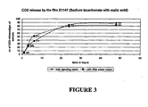
- the CO 2 releasing component may be a combination of a carbonate such as, but not limited to, sodium bicarbonate and/or calcium carbonate with an acid.
- Suitable acids include, but are not limited to, citric acid, maleic acid, malic acid, fumaric acid, polyacrylic acid, oxalic acid and/or mixtures thereof.
- the acid can be used in an anhydrous form to prevent the reaction from occurring prematurely.
- the acid is in its solid granular form and is substantially free of moisture.
- the CO 2 releasing component may be combined with the plastic component without the employing the co-continuous interconnecting channel morphology comprising at least three components discussed above. In one example, this can be used when one desires to slow down the CO 2 release.
- the acid particles may be employed as component "C" in creating co-continuous interconnecting channel morphology comprising at least three components. Consequently, in this embodiment, the composition should be processed at a temperature below the melt temperature of the acid so that the acid remains in its particle form.
- the acid can be selected with a low molecular weight and thus, will allow multiple H + ions to be released per mole of the compound. In this way, less acid by weight may be used to achieve substantial completion of the chemical reaction. It is also understood that particle size of the acid and/or carbonate can affect the efficiency of the reaction. For example, a particle size in the range of about 1 micron for calcium carbonate can be employed.
- a suitable composition for a three-phase polymer film is set forth below. All compositions are set forth on a mass/mass basis.
- Type (component "A”) Manufacturer Product Number 27% Ethylene-Olefin Copolymer Exxon Chemical Company 4023
- Type (component "B) 3% Ethylene oxide Union Carbide Corporation WSRN750.
- the calcium carbonate is included in the composition in particulate form. All sample componants are solid phase.
- the above-mentioned formulation was hand mixed. The processing of formulation was done using a single screw extruder. The temperature profile across the extruder was maintained at 121°C (250°F). The single screw extruder was primed/purged with Exact 4023. The formulation was then added to the extruder through the hopper. About 5 grams of extrudate was then collected coming out of the die.
- the collected extrudate was placed in between the two platen of the compression press and it was gently squeezed at 5000 psi and for about 10 seconds. Thickness of the sample was maintained by means of shims. The sample was then quenched. The final circular shape weighing 0.001 kg (1 gram) having an inch diameter and 0.0017 m (0.065-inch) thickness was cut by means of circular stamp. The circular shapes can be fixed to the cap liner in the way previously discussed.
- a total of 90 vials were used for the CO 2 release study 55 vials, used as controls, were purged with nitrogen. The other 35 vials (replicate for each time frame) were set up for CO 2 release test. Vial volume 0.12L (120cc). The vials are made of glass. The vials had crimped aluminum seals with red rubber septa in it.
- a MOCON PAC CHECK-650 Dual Head Space Analyzer device was used to measure the amount of carbon dioxide released by the sample.
- This analyzer employs an IR source and IR detector in the determination of the amount of CO 2 present at the time the sample is inspected.
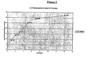
- the % carbon dioxide released by the sample was measured after 1 day, 2 days, 3 days, 5days, 7 days, 14 days, 28 days duration.
- the 55 control vial samples (5 replicates for each time period) are checked at 1 hr, 2hr, 4 hr, 8 hr, 24 hr, 2 days, 4 days, 7 days, 14 days, 21 days and 28 days for percent of oxygen inside the vials or leakage through the vial.
- Samples were removed from the vial and inserted into the MOCON instrument to detect the amount of CO 2 present in the following manner.
- A10 cc gas tight syringe was used.
- the syringe was emptied by pushing the plunger all the way in.
- the syringe needle was inserted through the rubber septa located in the lid of the aluminum-crimped seal.
- the syringe plunger was slowly pulled out until a gas sample of 5cc or more is in the syringe.
- the needle was inserted into the injection filter assembly on the front panel of the PAC CHECK 650 until the needle will not go any further.
- the syringe plunger was pushed to inject the sample into the PAC CHECK 650 at a rate of approximately 1 cc/second.
- the readouts on the MOCON instrument for the CO 2 and O 2 display are checked to insure the device is operating properly. These indicate that the sample was properly injected into the PAC CHECK 650.
- the Concentration of Oxygen and Carbon dioxide is displayed in the front panel in %.
- the control sample vials were filled with nitrogen. These vials are checked at above-mentioned time for percent of oxygen inside the vials or leakage through the vial.
- the % carbon dioxide in the room atmosphere was measured at the beginning of the experiment.
- the % carbon dioxide released by the sample was measured at selected intervals.
- the volume of the air inside the vial was calculated by filling the vial with water and weighing it after tarring the vial weight with filter paper and sample inside it. The difference in the % CO 2 reading was converted to the volume of the CO 2 released based on the vial volume. Then based on the weight of the sample the equivalent volume of CO 2 released/gm of the sample was calculated after implying a correction factor for the increase in pressure inside the vial.
Landscapes
- Chemical & Material Sciences (AREA)
- Chemical Kinetics & Catalysis (AREA)
- Medicinal Chemistry (AREA)
- Polymers & Plastics (AREA)
- Organic Chemistry (AREA)
- Health & Medical Sciences (AREA)
- Compositions Of Macromolecular Compounds (AREA)
- Packages (AREA)
- Details Of Rigid Or Semi-Rigid Containers (AREA)
- Closures For Containers (AREA)
- Wrappers (AREA)
- Gas Separation By Absorption (AREA)
- Non-Alcoholic Beverages (AREA)
- Internal Circuitry In Semiconductor Integrated Circuit Devices (AREA)
- Measurement Of The Respiration, Hearing Ability, Form, And Blood Characteristics Of Living Organisms (AREA)
- Carbon And Carbon Compounds (AREA)
- Treating Waste Gases (AREA)
Applications Claiming Priority (3)
| Application Number | Priority Date | Filing Date | Title |
|---|---|---|---|
| US25667700P | 2000-12-19 | 2000-12-19 | |
| US256677P | 2000-12-19 | ||
| PCT/US2001/049532 WO2002050178A1 (en) | 2000-12-19 | 2001-12-19 | Interconnecting channel morphology composition for releasing co2 |
Publications (3)
| Publication Number | Publication Date |
|---|---|
| EP1363970A1 EP1363970A1 (en) | 2003-11-26 |
| EP1363970A4 EP1363970A4 (en) | 2005-01-12 |
| EP1363970B1 true EP1363970B1 (en) | 2006-03-15 |
Family
ID=22973152
Family Applications (1)
| Application Number | Title | Priority Date | Filing Date |
|---|---|---|---|
| EP01991433A Expired - Lifetime EP1363970B1 (en) | 2000-12-19 | 2001-12-19 | Interconnecting channel morphology composition for releasing co2 |
Country Status (9)
| Country | Link |
|---|---|
| US (1) | US6852783B2 (https=) |
| EP (1) | EP1363970B1 (https=) |
| JP (1) | JP4382350B2 (https=) |
| CN (1) | CN1239588C (https=) |
| AT (1) | ATE320468T1 (https=) |
| AU (1) | AU2002231160A1 (https=) |
| CA (1) | CA2432858C (https=) |
| DE (1) | DE60118031T2 (https=) |
| WO (1) | WO2002050178A1 (https=) |
Families Citing this family (10)
| Publication number | Priority date | Publication date | Assignee | Title |
|---|---|---|---|---|
| US7314895B2 (en) * | 2001-12-19 | 2008-01-01 | Csp Technologies, Inc. | Thermoplastic composition comprising a CO2 releasing material |
| JP4585566B2 (ja) * | 2004-02-27 | 2010-11-24 | ビーピー・コーポレーション・ノース・アメリカ・インコーポレーテッド | プラスチックパッケージングの保存寿命を延ばすための二酸化炭素調節剤の使用 |
| CN1925755B (zh) * | 2004-02-27 | 2011-08-31 | Bp北美公司 | 使用二氧化碳调节剂延长塑料包装的保存寿命 |
| US9339789B2 (en) | 2004-10-12 | 2016-05-17 | Multisorb Technologies, Inc. | Thermoset desiccant product and method for making same |
| US7501011B2 (en) | 2004-11-09 | 2009-03-10 | Multisorb Technologies, Inc. | Humidity control device |
| US8097221B2 (en) | 2005-01-21 | 2012-01-17 | Multisorb Technologies, Inc. | Lamp assembly |
| US8853124B2 (en) | 2005-01-21 | 2014-10-07 | Multisorb Technologies, Inc. | Resin bonded sorbent |
| US7989388B2 (en) | 2005-01-21 | 2011-08-02 | Multisorb Technologies, Inc. | Resin bonded sorbent |
| US8057586B2 (en) | 2008-07-28 | 2011-11-15 | Multisorb Technologies, Inc. | Humidity control for product in a refrigerator |
| EP2990638A1 (de) * | 2012-01-11 | 2016-03-02 | CeramTec GmbH | Aktormodul mit einem in einem gehäuse angeordneten vielschichtaktor und konstant extrem niedrigen leckstrom an der aktoroberfläche |
Family Cites Families (7)
| Publication number | Priority date | Publication date | Assignee | Title |
|---|---|---|---|---|
| US2941964A (en) * | 1954-11-16 | 1960-06-21 | Koppers Co Inc | Composition comprising polystyrene, volatile organic solvent and a carbon dioxide liberating agent, and process of simultaneously foaming and extruding said composition |
| US3344092A (en) * | 1965-04-22 | 1967-09-26 | Koppers Co Inc | Foamable styrene polymer compositions containing a mixture of a carbonate and a bicarbonate as blowing agents |
| US6740731B2 (en) * | 1988-08-08 | 2004-05-25 | Cargill Dow Polymers Llc | Degradation control of environmentally degradable disposable materials |
| US5234963A (en) * | 1992-05-13 | 1993-08-10 | Gaia Research | Production of encapsulated chemical foaming concentrates |
| US6323269B1 (en) * | 1993-12-22 | 2001-11-27 | Imerys Pigments, Inc. | Mineral containing thermoplastic granules |
| US6344509B1 (en) * | 1994-12-22 | 2002-02-05 | Taiyo Kagaku Co., Ltd. | Thermoplastic resin compositions |
| DE19637368A1 (de) * | 1996-09-13 | 1998-03-19 | Basf Ag | Flammgeschützte thermoplastische Formmassen |
-
2001
- 2001-12-19 EP EP01991433A patent/EP1363970B1/en not_active Expired - Lifetime
- 2001-12-19 AT AT01991433T patent/ATE320468T1/de not_active IP Right Cessation
- 2001-12-19 CN CN01821978.0A patent/CN1239588C/zh not_active Expired - Lifetime
- 2001-12-19 CA CA2432858A patent/CA2432858C/en not_active Expired - Lifetime
- 2001-12-19 JP JP2002552064A patent/JP4382350B2/ja not_active Expired - Lifetime
- 2001-12-19 US US10/033,973 patent/US6852783B2/en not_active Expired - Lifetime
- 2001-12-19 WO PCT/US2001/049532 patent/WO2002050178A1/en not_active Ceased
- 2001-12-19 DE DE60118031T patent/DE60118031T2/de not_active Expired - Lifetime
- 2001-12-19 AU AU2002231160A patent/AU2002231160A1/en not_active Abandoned
Also Published As
| Publication number | Publication date |
|---|---|
| DE60118031T2 (de) | 2006-12-07 |
| US6852783B2 (en) | 2005-02-08 |
| CA2432858A1 (en) | 2002-06-27 |
| DE60118031D1 (de) | 2006-05-11 |
| CN1486343A (zh) | 2004-03-31 |
| EP1363970A1 (en) | 2003-11-26 |
| EP1363970A4 (en) | 2005-01-12 |
| WO2002050178A1 (en) | 2002-06-27 |
| US20020173572A1 (en) | 2002-11-21 |
| CN1239588C (zh) | 2006-02-01 |
| JP2004536158A (ja) | 2004-12-02 |
| ATE320468T1 (de) | 2006-04-15 |
| AU2002231160A1 (en) | 2002-07-01 |
| CA2432858C (en) | 2010-02-16 |
| JP4382350B2 (ja) | 2009-12-09 |
Similar Documents
| Publication | Publication Date | Title |
|---|---|---|
| EP1363970B1 (en) | Interconnecting channel morphology composition for releasing co2 | |
| US7056971B2 (en) | Essentially gas-impermeable thermoplastic elastomer | |
| US4311808A (en) | Cling film composition of olefin polymer blend | |
| US5211974A (en) | Containers and compositions for sealing them | |
| US3695477A (en) | Plastisols and gaskets | |
| US10174155B2 (en) | Oxygen scavenging copolymers made from cyclic aliphatic monomers | |
| EP2820101B1 (en) | Closure liner composition with improved oxygen reduction | |
| KR100196481B1 (ko) | 밀폐용 가스켓 및 이를 포함하는 용기 | |
| EP0488491B1 (en) | Package including containers and use of compositions for sealing these containers | |
| US6460271B2 (en) | Insert having interconnecting channel morphology for aldehyde absorption | |
| EP2443169B1 (en) | Oxygen scavenging terpolymers | |
| KR100601146B1 (ko) | 플라스틱 병뚜껑용 폴리에틸렌 수지조성물 및 이로부터제조된 성형품 | |
| JP4207312B2 (ja) | 成型体用組成物及び成型体 | |
| EP1845027A1 (en) | Compositions for hermetic container closures and hermetic closures comprising same | |
| KR20050119543A (ko) | 산소 흡수 및 수분 흡수가 가능한 수지 조성물 |
Legal Events
| Date | Code | Title | Description |
|---|---|---|---|
| PUAI | Public reference made under article 153(3) epc to a published international application that has entered the european phase |
Free format text: ORIGINAL CODE: 0009012 |
|
| 17P | Request for examination filed |
Effective date: 20030613 |
|
| AK | Designated contracting states |
Kind code of ref document: A1 Designated state(s): AT BE CH CY DE DK ES FI FR GB GR IE IT LI LU MC NL PT SE TR |
|
| A4 | Supplementary search report drawn up and despatched |
Effective date: 20041130 |
|
| RIC1 | Information provided on ipc code assigned before grant |
Ipc: 7C 08K 3/26 A Ipc: 7C 08L 23/08 B Ipc: 7C 08L 101/00 B |
|
| 17Q | First examination report despatched |
Effective date: 20050114 |
|
| RAP1 | Party data changed (applicant data changed or rights of an application transferred) |
Owner name: CSP TECHNOLOGIES, INC. |
|
| GRAP | Despatch of communication of intention to grant a patent |
Free format text: ORIGINAL CODE: EPIDOSNIGR1 |
|
| GRAS | Grant fee paid |
Free format text: ORIGINAL CODE: EPIDOSNIGR3 |
|
| GRAA | (expected) grant |
Free format text: ORIGINAL CODE: 0009210 |
|
| AK | Designated contracting states |
Kind code of ref document: B1 Designated state(s): AT BE CH CY DE DK ES FI FR GB GR IE IT LI LU MC NL PT SE TR |
|
| PG25 | Lapsed in a contracting state [announced via postgrant information from national office to epo] |
Ref country code: FI Free format text: LAPSE BECAUSE OF FAILURE TO SUBMIT A TRANSLATION OF THE DESCRIPTION OR TO PAY THE FEE WITHIN THE PRESCRIBED TIME-LIMIT Effective date: 20060315 Ref country code: AT Free format text: LAPSE BECAUSE OF FAILURE TO SUBMIT A TRANSLATION OF THE DESCRIPTION OR TO PAY THE FEE WITHIN THE PRESCRIBED TIME-LIMIT Effective date: 20060315 Ref country code: BE Free format text: LAPSE BECAUSE OF FAILURE TO SUBMIT A TRANSLATION OF THE DESCRIPTION OR TO PAY THE FEE WITHIN THE PRESCRIBED TIME-LIMIT Effective date: 20060315 |
|
| REG | Reference to a national code |
Ref country code: GB Ref legal event code: FG4D Ref country code: CH Ref legal event code: EP |
|
| REG | Reference to a national code |
Ref country code: IE Ref legal event code: FG4D |
|
| REF | Corresponds to: |
Ref document number: 60118031 Country of ref document: DE Date of ref document: 20060511 Kind code of ref document: P |
|
| PG25 | Lapsed in a contracting state [announced via postgrant information from national office to epo] |
Ref country code: SE Free format text: LAPSE BECAUSE OF FAILURE TO SUBMIT A TRANSLATION OF THE DESCRIPTION OR TO PAY THE FEE WITHIN THE PRESCRIBED TIME-LIMIT Effective date: 20060615 Ref country code: DK Free format text: LAPSE BECAUSE OF FAILURE TO SUBMIT A TRANSLATION OF THE DESCRIPTION OR TO PAY THE FEE WITHIN THE PRESCRIBED TIME-LIMIT Effective date: 20060615 |
|
| PG25 | Lapsed in a contracting state [announced via postgrant information from national office to epo] |
Ref country code: ES Free format text: LAPSE BECAUSE OF FAILURE TO SUBMIT A TRANSLATION OF THE DESCRIPTION OR TO PAY THE FEE WITHIN THE PRESCRIBED TIME-LIMIT Effective date: 20060626 |
|
| REG | Reference to a national code |
Ref country code: CH Ref legal event code: NV Representative=s name: KIRKER & CIE SA |
|
| PG25 | Lapsed in a contracting state [announced via postgrant information from national office to epo] |
Ref country code: PT Free format text: LAPSE BECAUSE OF FAILURE TO SUBMIT A TRANSLATION OF THE DESCRIPTION OR TO PAY THE FEE WITHIN THE PRESCRIBED TIME-LIMIT Effective date: 20060816 |
|
| ET | Fr: translation filed | ||
| PG25 | Lapsed in a contracting state [announced via postgrant information from national office to epo] |
Ref country code: IE Free format text: LAPSE BECAUSE OF NON-PAYMENT OF DUE FEES Effective date: 20061219 |
|
| PGFP | Annual fee paid to national office [announced via postgrant information from national office to epo] |
Ref country code: NL Payment date: 20061220 Year of fee payment: 6 |
|
| PG25 | Lapsed in a contracting state [announced via postgrant information from national office to epo] |
Ref country code: LI Free format text: LAPSE BECAUSE OF NON-PAYMENT OF DUE FEES Effective date: 20061231 Ref country code: MC Free format text: LAPSE BECAUSE OF NON-PAYMENT OF DUE FEES Effective date: 20061231 Ref country code: CH Free format text: LAPSE BECAUSE OF NON-PAYMENT OF DUE FEES Effective date: 20061231 |
|
| PLBE | No opposition filed within time limit |
Free format text: ORIGINAL CODE: 0009261 |
|
| STAA | Information on the status of an ep patent application or granted ep patent |
Free format text: STATUS: NO OPPOSITION FILED WITHIN TIME LIMIT |
|
| 26N | No opposition filed |
Effective date: 20061218 |
|
| REG | Reference to a national code |
Ref country code: CH Ref legal event code: PL |
|
| PG25 | Lapsed in a contracting state [announced via postgrant information from national office to epo] |
Ref country code: GR Free format text: LAPSE BECAUSE OF FAILURE TO SUBMIT A TRANSLATION OF THE DESCRIPTION OR TO PAY THE FEE WITHIN THE PRESCRIBED TIME-LIMIT Effective date: 20060616 |
|
| PG25 | Lapsed in a contracting state [announced via postgrant information from national office to epo] |
Ref country code: LU Free format text: LAPSE BECAUSE OF NON-PAYMENT OF DUE FEES Effective date: 20061219 Ref country code: TR Free format text: LAPSE BECAUSE OF FAILURE TO SUBMIT A TRANSLATION OF THE DESCRIPTION OR TO PAY THE FEE WITHIN THE PRESCRIBED TIME-LIMIT Effective date: 20060315 |
|
| NLV4 | Nl: lapsed or anulled due to non-payment of the annual fee |
Effective date: 20080701 |
|
| PG25 | Lapsed in a contracting state [announced via postgrant information from national office to epo] |
Ref country code: CY Free format text: LAPSE BECAUSE OF FAILURE TO SUBMIT A TRANSLATION OF THE DESCRIPTION OR TO PAY THE FEE WITHIN THE PRESCRIBED TIME-LIMIT Effective date: 20060315 Ref country code: NL Free format text: LAPSE BECAUSE OF NON-PAYMENT OF DUE FEES Effective date: 20080701 |
|
| PGFP | Annual fee paid to national office [announced via postgrant information from national office to epo] |
Ref country code: IT Payment date: 20101224 Year of fee payment: 10 |
|
| PG25 | Lapsed in a contracting state [announced via postgrant information from national office to epo] |
Ref country code: IT Free format text: LAPSE BECAUSE OF NON-PAYMENT OF DUE FEES Effective date: 20121219 |
|
| REG | Reference to a national code |
Ref country code: FR Ref legal event code: PLFP Year of fee payment: 15 |
|
| REG | Reference to a national code |
Ref country code: FR Ref legal event code: PLFP Year of fee payment: 16 |
|
| REG | Reference to a national code |
Ref country code: FR Ref legal event code: PLFP Year of fee payment: 17 |
|
| PGFP | Annual fee paid to national office [announced via postgrant information from national office to epo] |
Ref country code: GB Payment date: 20201228 Year of fee payment: 20 Ref country code: FR Payment date: 20201227 Year of fee payment: 20 |
|
| PGFP | Annual fee paid to national office [announced via postgrant information from national office to epo] |
Ref country code: DE Payment date: 20201229 Year of fee payment: 20 |
|
| REG | Reference to a national code |
Ref country code: DE Ref legal event code: R071 Ref document number: 60118031 Country of ref document: DE |
|
| REG | Reference to a national code |
Ref country code: GB Ref legal event code: PE20 Expiry date: 20211218 |
|
| PG25 | Lapsed in a contracting state [announced via postgrant information from national office to epo] |
Ref country code: GB Free format text: LAPSE BECAUSE OF EXPIRATION OF PROTECTION Effective date: 20211218 |