EP1363243A1 - Dispositif et procede de reconnaissance de cible - Google Patents
Dispositif et procede de reconnaissance de cible Download PDFInfo
- Publication number
- EP1363243A1 EP1363243A1 EP02701543A EP02701543A EP1363243A1 EP 1363243 A1 EP1363243 A1 EP 1363243A1 EP 02701543 A EP02701543 A EP 02701543A EP 02701543 A EP02701543 A EP 02701543A EP 1363243 A1 EP1363243 A1 EP 1363243A1
- Authority
- EP
- European Patent Office
- Prior art keywords
- target
- template
- recognizing
- control signal
- image
- Prior art date
- Legal status (The legal status is an assumption and is not a legal conclusion. Google has not performed a legal analysis and makes no representation as to the accuracy of the status listed.)
- Granted
Links
Images

Classifications
-
- G—PHYSICS
- G06—COMPUTING OR CALCULATING; COUNTING
- G06T—IMAGE DATA PROCESSING OR GENERATION, IN GENERAL
- G06T7/00—Image analysis
- G06T7/20—Analysis of motion
- G06T7/215—Motion-based segmentation
-
- G—PHYSICS
- G06—COMPUTING OR CALCULATING; COUNTING
- G06F—ELECTRIC DIGITAL DATA PROCESSING
- G06F18/00—Pattern recognition
- G06F18/20—Analysing
- G06F18/28—Determining representative reference patterns, e.g. by averaging or distorting; Generating dictionaries
-
- G—PHYSICS
- G06—COMPUTING OR CALCULATING; COUNTING
- G06T—IMAGE DATA PROCESSING OR GENERATION, IN GENERAL
- G06T7/00—Image analysis
- G06T7/20—Analysis of motion
- G06T7/269—Analysis of motion using gradient-based methods
-
- G—PHYSICS
- G06—COMPUTING OR CALCULATING; COUNTING
- G06V—IMAGE OR VIDEO RECOGNITION OR UNDERSTANDING
- G06V10/00—Arrangements for image or video recognition or understanding
- G06V10/70—Arrangements for image or video recognition or understanding using pattern recognition or machine learning
- G06V10/77—Processing image or video features in feature spaces; using data integration or data reduction, e.g. principal component analysis [PCA] or independent component analysis [ICA] or self-organising maps [SOM]; Blind source separation
- G06V10/772—Determining representative reference patterns, e.g. averaging or distorting patterns; Generating dictionaries
Definitions
- the present invention relates to a target recognizing device and a target recognizing method for recognizing a target by using templates.
- various sensors such as a camera are used to obtain a scene including a target, being an object to be recognized, as image information,and target recognition is conducted based on the image information and fragmentary knowledge with respect to the target.
- the main object of the target recognition is to grasp the scene including the target from the image information as accurately as possible, and rebuild the target.
- a template matching method is frequently used, which obtains a consistency between the target in the image information, and many templates prepared beforehand with respect to the target.
- the following method can be considered. That is to say, at first, a plurality of image information relating to a target point is stored beforehand as templates. Image information including the target point is then obtained by a camera or the like mounted therein, to extract an area having the best consistency with the template stored in advance, from the image information. The robot then moves toward the direction corresponding to the extracted area, by the autonomously shift device.
- an optical flow is frequently used.
- the optical flow is a vector representation of the direction of movement at one point on the image and the magnitude of the velocity thereof.
- the target recognizing device in the autonomously movable robot however, the scene photographed by a camera or the like changes moment by moment due to the movement of the robot, and even in the case of the same target, the size of the target occupying the obtained image information changes. Therefore, even by simply using the optical flow, it is difficult to perform accurate target recognition, and many templates corresponding to the respective situations become necessary.
- the first aspect of the present invention provides a device comprising a template storing device which stores a template for recognizing a target, an image acquiring device which acquires continuous images including the target, a recognition processing device which detects an optical flow between at least two images of the continuous images to obtain an evaluation function value based on the optical flow; and an update device which updates the template stored in the template storing device, based on the image including the target acquired by the image acquiring device, until the evaluation function value exceeds a predetermined value.
- the device further comprises a driving device which rotates the image acquiring device, and an operation instruction device which outputs an operation instruction to the driving device based on the instruction from the recognition processing device, and the operation instruction device outputs an operation instruction for stopping the rotational motion when the evaluation function value exceeds the predetermined value.
- the image acquiring device is rotated based on the instruction from the recognition processing device, and when a predetermined condition is satisfied, the rotational motion is stopped.
- the target recognizing device can perform predetermined operations such as rotating the image acquiring device in a direction of a target recognized by using templates, and shift the image acquiring device, and hence can be preferably used for controlling a robot.
- the device further comprises: a control signal receiving device which receives a control signal indicating a timing at which the template is updated; and an identification device which identifies the content of the control signal received by the control signal receiving device and informs the update device of the content, and the update device updates the template corresponding to an identification result of the control signal.
- update of the template for recognizing the target can be performed according to an instruction from outside, and when the image acquiring device turns to an optional direction, this direction can be designated as a target direction. Moreover, since the update processing of the template for recognizing the target can be performed from the image obtained only when the image acquiring device turns to a predetermined target direction, more reliable template generation can be performed.
- the evaluation function value is obtained by comparing the degree of approximation of the template and the image including the target, setting a shift quantity with respect to the approximating pixel to the position in the template, and summing up shift quantities for all pixels in the whole templates.
- the degree of approximation of the image including the target and the template is compared, the shift quantity of the approximating pixel to the target pixel in the template is set, and the shift quantities for all pixels in the whole templates are summed up, to obtain the evaluation function value.
- At least two-types of templates for use at the time of updating while rotating in one direction one of which is added with a positive-polarity weighting value, and another one of which is added with a negative-polarity weighting value.
- a plurality of template groups is provided depending on the rotation direction of the image acquiring device.
- the seventh aspect of the present invention provides a target identification method comprises a template storing step in which a template for recognizing a target is stored, an image acquiring step in which continuous images including the target are acquired by self-rotational motion; a recognition processing step in which an optical flow between at least two images of the continuous images is detected, to obtain an evaluation function value based on the optical flow, and an update step in which the template stored by the template storing step is updated based on an image including the target acquired by the image acquiring step, by template update timing instructed from outside, until the evaluation function value exceeds a predetermined value.
- the eighth aspect of the present invention provides a computer program for target identification method to be executed by a computer, the program comprises the steps of template storage processing for storing a template for recognizing a target, image acquisition processing for acquiring continuous images including the target, recognition processing for detecting an optical flow between at least two images of the continuous images, to obtain an evaluation function value based on the optical flow, and update processing for updating the template stored by the template storage processing, based on an image including the target acquired by the image acquisition processing, until the evaluation function value exceeds a predetermined value.
- the image acquisition program to be executed in a computer comprises the steps of driving processing for performing self-rotational motion, and operation instruction processing for outputting operation instructions with respect to the driving processing, based on instructions from the recognition processing, are further executed by the computer, and the operation instruction processing outputs an operation instruction for stopping rotational motion at a point in time when the evaluation function value exceeds a predetermined value.
- the computer program for executing the target identification method in a computer comprises the steps of control signal reception processing for receiving a control signal indicating a timing at which the template is updated, and identification processing for identifying the content of the control signal received by the control signal reception processing and informing the content with respect to the update processing are further executed by the computer, wherein the update processing updates the template corresponding to an identification result of the control signal.
- the target identification program comprises the steps of comparing the degree of approximation of the template and the image including the target, setting a shift quantity of the approximating pixel to the target position, and summing up the shift quantities for all pixels corresponding to all pixels of the templates.
- a plurality of templates are provided, which differ depending on the rotation direction of the image acquiring device.
- the present invention among the plurality of templates to be updated at the time of rotating in the same direction, there are at least two types of templates, one of which is added with a positive-polarity weighting value and another one of which is added with a negative-polarity weighting value.
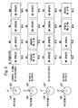
- FIG. 1 is a block diagram showing the configuration of this embodiment.
- Reference symbol 1 denotes a robot camera comprising a camera 11 (for example, a CCD camera) for acquiring peripheral images, and a motor 12 for rotating the camera 11 in the horizontal direction to direct the optical axis of the camera 11 to an optional direction.
- the motor 12 is provided with an encoder (not shown), so that the direction (angle of rotation) of the camera 11 at the time of rotational motion can be detected by a value of the encoder.
- Reference symbol 2 denotes an arithmetic operation section, which comprises a target recognition section 21 and a template control section 22.
- Reference symbol 23 denotes an image storage section for storing images taken by the camera 11, and images stored herein are sampled and quantized images.
- Reference symbol 24 denotes a recognition processing section for recognizing a target based on the image stored in the image storage section 23.
- Reference symbol 25 denotes an operation instruction section for outputting operation instructions to the robot camera 1, based on the target recognition result in the recognition processing section 24.
- Reference symbol 26 denotes a control signal reception section for receiving a control signal Rn transmitted from outside or from the robot camera 1.
- Reference symbol 27 denotes an identification section for identifying the control signal Rn and issuing an instruction based on the identification result.
- Reference symbol 28 denotes an update section for updating a template stored in a template storage section 29.
- n pieces (n is a natural number) of templates Mn are stored in advance in the template storage section 29 in the template control section 22.
- the camera 11 provided in the robot camera 1 takes images of the external environment as seen from the robot camera 1 continuously, and the image information is sequentially stored in the image storage section 23 in the target recognition section 21.
- the recognition processing section 24 in the target recognition section 21 calculates the optical flow between the continuous images taken out from the image storage section 23, and changes in the operation are obtained for each local portion in the image to extract a characteristic portion in the image.
- the recognition processing section 24 searches the template Mn corresponding to the input image in the template storage section 29, to perform recognition processing of a target in the external environment.
- the processing result in the recognition processing section 24 is provided to the operation instruction section 25.
- the operation instruction section 25 Upon reception of the processing result, the operation instruction section 25 provides an operation instruction corresponding to the processing result in the recognition processing section 24, to the motor 12 in the robot camera 1.
- the motor 12 generates a driving force corresponding to the operation instruction, to thereby cause spontaneous rotational motion of the camera 11.
- the templates Mn stored in the template storage section 29 are updated as required. Update of the templates Mn is performed corresponding to a control signal Rn provided from outside of the target recognizing device, or a control signal Rn transmitted from the robot camera 1 at the timing when the camera turns to a direction including the target.
- the control signal Rn is received by the control signal reception section 26, and the content thereof is identified by the identification section 27.
- the identification section 27 provides an update instruction corresponding to the identification result, to the update section 28.
- the update section 28 updates the corresponding template Mn based on the received update instruction.
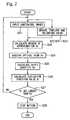
- FIG. 2 is a flowchart showing the operation for creating the template Mn corresponding to the image including a target.
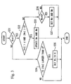
- FIG. 3 is a flowchart showing the operation in step S22 shown in FIG. 2.
- the operation instruction section 25 issues an instruction for performing rotational motion, to the motor 12.
- the motor 12 drives, to rotate the camera 11 about an axis perpendicular to the ground.
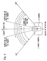
- FIG. 4 is a diagram of the robot camera 1 as seen from the above.
- the computation section 2 is not shown in FIG. 4, the computation section 2 is installed in the vicinity of the robot camera 1.
- the camera 11 performs reciprocating rotational motion within the range of rotational motion of from -50° to 50°, due to driving of the motor 12.
- the direction to which the optical axis of the camera 11 is directed is assumed to be 0°. This direction of 0° is the direction where the target exists (target direction).
- the image in the target direction is acquired, and a template corresponding to the acquired image is created.
- the camera 11 is rotated to obtain the optical flow from, the image in the vicinity of the target direction and the image in the target direction, which is then used for creating and updating the template.
- the range of rotational motion is designated as up to 50° right and left.
- the encoder provided in the motor 12 outputs "1" as the control signal Rn, when the angle of rotation is 0°.
- This control signal Rn is received by the control signal reception section 26.
- the computation section 2 can detect that the camera 11 has turned to the target direction, and creates and updates the template Mn, by using the image at this timing.
- the camera 11 acquires an image in the direction of 0° (target direction) indicated by reference symbol S.
- the camera 11 then rotates to the direction of-50° and returns to the direction of 0°.
- the camera 11 acquires images at a certain sampling interval.
- the camera 11 rotates to the direction of +50° and returns to the direction of 0°.
- the camera 11 acquires images at a certain sampling interval.
- the optical flow is calculated from a series of continuous images obtained here.
- the images acquired by the camera 11 are sequentially stored in the image storage section in the computation section 2 (step S21 in FIG. 2).
- the stored image is described here as an image It (x, y).
- Each pixel in the image It (x, y) is expressed by a gray value of 8 bits (256 gradations).
- the update section 28 updates the template Mn and the weighting value Wn (step S22). Details of the processing in step S22 will be described later.
- the recognition processing section 24 calculates the degree of approximation Sn (x, y) between the newest image It (x, y) stored in the image storage section 23 and each pixel in the n templates Mn held in the recognition processing section 24 beforehand (step S23).
- the operation for calculating the degree of approximation Sn (x, y) will be described here, with reference to FIGS. 5 and 6.
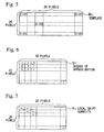
- FIG. 5 is a diagram showing one template Mn representing the templates Mn, which are previously stored.
- FIG. 6 is a diagram showing the degree of approximation Sn for each pixel obtained by the processing in step S23.
- each template Mn is constituted of 20 ⁇ 20 pieces of pixels, and the position of each pixel is expressed by the coordinates (x, y).
- the gray value of each pixel in all templates Mn in the initial state is set to any value of 256 gradations (0 to 255) at random.
- the construction may be such that the template storage section 29 stores a transform value for each of the 20 ⁇ 20 pixels, by using a Fourier transform, a Gabor transform or a Wavelet transform, instead of the gray value.
- the template Mn can correspond to an optional position on the input image It acquired by the camera 11. For example, if the pixel It (0, 0) at the upper left of the input image It is made to agree with the pixel Mn (0, 0) at the upper left of the template Mn, the image recognition for 20 ⁇ 20 pixels at the upper left of the input image It is carried out, by using the template Mn.
- the degree of approximation Sn can be obtained by performing for each pixel, processing where the newest image It (x, y) stored in the image storage section 23 is compared with the template Mn (x, y) stored in the template storage section 29 for each pixel to obtain a difference in the gray value, and if the difference is smaller than a predetermined value, it is assumed that the image It (x, y) approximates to the template Mn (x, y), and if the difference is larger than the predetermined value, it is assumed that the image It (x, y) does not approximate to the template Mn (x, y).
- "1" is set to only the approximating pixels.
- the recognition processing section 24 calculates the optical flow by using an input image It - 1 (x, y) obtained immediately before the newest input image It (x, y), and the input image It (x, y), to obtain the optical flow Vx (step S24).
- Vx (x, y) obtained by the equation (2) is designated as the optical flow.
- the recognition processing section 24 calculates the evaluation function value B by the following equation (4) (step S26): where, Wn (x, y) is a weighting value with respect to the pixel, which can take a positive or negative value, and ⁇ n is a weighting value for each template in a range of 0 ⁇ ⁇ n ⁇ 1.
- This Wn (x, y) is a value obtained in step S22.
- the recognition processing section 24 determines whether the absolute value of the obtained evaluation function value B is larger than a predetermined threshold k (step S27). As a result of this determination, if the evaluation function value B is not larger than the threshold k, control returns to step S21 and step S22, to repeat the processing. On the other hand, if the evaluation function value B is larger than the threshold k, the recognition processing section 24 informs the operation instruction section 25 that the template creation processing has finished. In response to this, the operation instruction section 25 issues an instruction for stopping the drive of the motor 12 to the motor 12. As a result, the rotational motion of the camera 11 stops, with the camera 11 turning to the target direction (step S28).
- the template Mn corresponding to the image in the target direction is complete, thereby enabling the target recognition processing using this template Mn.
- the threshold k is set to a very low value, the evaluation function value B is likely to exceed the threshold k. Therefore, the camera 11 can be quickly located at a position, which is considered to be the target direction.
- the threshold k is set to a value too low, there is the possibility that the camera 11 is located erroneously in a direction where image information similar to the target direction is obtained.
- the threshold k is set to a value too high, the camera 11 is reliably located in the true target direction, but it takes too much time.
- the threshold k corresponding to various parameters, such as the complexity of the environment where the robot camera I is placed, the recognition accuracy required for the target recognizing device and the time required for recognition, the processing capability of the computation section 2, the number of pixels in the template Mn and the number of templates Mn, and the rotational speed of the camera 11.
- FIG. 3 is a flowchart showing the operation of the update processing for the template Mn and the weighting value Wn.
- the identification section 27 determines whether the control signal Rn is "1" (ON) (step S31).
- This control signal Rn is such a signal that when the camera 11 turns to the target direction (the direction of 0° shown in FIG. 4), "1" is output.
- the control signal Rn is not "1"
- the update section 28 sets the-weighting value Wn to "0" (step S35). This processing means that a pixel having the size of Vn larger than the predetermined value, though the control signal Rn " 1" has not been input, is regarded as noise as a result of having caught an object other than the target, and the record of this portion is cancelled (deleted) by designating the weighting value Wn as "0", so that the update processing for the template and the like is not executed.
- step S31 when the control signal Rn is "1", the update section 28 determines whether
- the respective update is performed according to the following equations (5) and (6).
- Wn (x, y) Wn (x, y) + w where w denotes an initial value of the weighting value.
- Mn (x, y) Mn - q (Mn - It) where q denotes a fixed value set to any figure in the range of 0 ⁇ q ⁇ 1.
- the initial value w is added to the weighting value Wn to increase the weighting, so that the template Mn is brought close to the gray value of the pixel in the input image It.
- the characteristic point of the target is emphasized (extracted) in the input image It, and the portion which is not detected stably in the target direction, such as a characteristic point of an object existing irregularly, is cut out.
- step S32 if
- is not larger than d, or Wn is not larger than 0, the update section 28 determines whether the weighting value Wn is "0" (step S36). As a result of the determination, if Wn is not 0, the processing finishes. On the other hand, when Wn 0, the update section 28 sets the template Mn and the weighting value Wn (step S37). This processing is performed even if the target may have been caught, but since the weighting value Wn is still 0, it is determined that the image of this portion is obtained for the first time, and Wn is set to w (initial value), and the pixel is set to a gray value of a corresponding pixel in the input image It.
- FIG. 8 is a diagram for explaining the update processing for the template Mn and the weighting value Wn.
- the templates Mn are four (M I to M4).
- patterns 1 and 3 show the state where the camera 11 is not directed to the target direction (direction of 0°).
- Patterns 2 and 4 show the state where the camera 11 is directed to the target direction (direction of 0°).
- the templates M1 and M2 are updated, but weighting values W1 and W2 with polarities opposite to each other are provided.
- the templates M3 and M4 are updated, but weighting values W3 and W4 with polarities opposite to each other are provided. This is for improving the robustness with respect to the optical flow by means of an object detected in the actual environment. For example, in the actual environment, the boundary portion of an object is likely to be detected as an optical flow in a direction opposite to that of the face portion, and the detection result is unstable. Therefore, in order to improve the detection accuracy as a whole, weighting values Wn having opposite polarities are used to clarify the boundary portion.
- the updated templates Mn are grouped (into M1 and M2, or M3 and M4) according to a case where the camera 11 reaches the direction of 0° (target direction) counterclockwise (pattern 2), and a case where the camera 11 reaches the direction of 0° (target direction) clockwise (pattern 4).
- This is for coping with the imbalance of the movement in the target direction with respect to the movement of the camera 11.
- the templates Mn are grouped for each direction of rotation.
- the characteristic of the optical flow generated by an object existing in the target direction, when the camera 11 is rotated counterclockwise, is reflected in the templates M1 and M2
- the characteristic of the optical flow generated by the object existing in the target direction, when the camera 11 is rotated clockwise is reflected in the templates M3 and M4.
- the camera 11 may be set so as to continue to rotate in either one direction.
- a target recognizing device needs only to record and hold the templates M1 and M2, or the templates M3 and M4.
- the construction may be such that a stopping instruction is issued before the target direction (0°) by a predetermined angle, or the camera 11 is made to return by a predetermined angle and stop reliably, with the camera facing the target direction.
- the angle of rotation of the camera 11 is not limited to ⁇ 50°, and other angles may be employed.
- the update processing for the templates Mn and the like may be performed at an angle other than 0°, for example, at a point in time when the camera 11 turns to a direction where a pixel or pattern having a particular density exists.
- the template used for recognizing a predetermined target is complete, and stored in the template storage section 29.
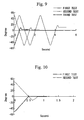
- FIG. 9 is a diagram showing tracks of the direction of the camera 11.
- the first test when in total four control signals Rn were provided, the above described at-end condition was satisfied and the test finished.
- the template Mn (x, y) having had a random value becomes a sufficient value for recognizing the target in the direction of 0°.
- the second test was conducted by using the template Mn (x, y) obtained as a result of the first test.
- the control signal Rn was provided.
- the test finished by providing two control signals Rn.
- the initial value was different from that of the first test, corresponding to the target.
- the template obtained as a result of the second test was used, to start the test from the state where the camera 11 was directed in the direction of-50°.
- the at-end condition was satisfied by only providing a first control signal. In other words, it is seen that the template required for recognizing the target has been nearly completed from the initial stage.
- the template is updated to one sufficient for recognizing the target, and the camera is located in the vicinity of 0° in the target direction at an early stage.
- FIG. 10 is a diagram showing a track of the direction of the camera 11, when the target recognition processing is performed by using a template sufficient for recognizing the target, obtained by repeating the template update processing. As shown in FIG. 10, it is seen that even if the direction to which the camera 11 is made to turn at first is counterclockwise, or clockwise, the target is recognized quickly in substantially the same time, and the camera 11 is located in the target direction.
- the robot camera 1 and the computation section 2 may be connected by wire, but a radio communication apparatus may be provided, and the information exchanged by using radio communication.
- the robot camera 1 and the computation section 2 may be integrated.
- control signal Rn when a control signal Rn is transmitted from-outside to the control signal reception section 26, the output timing of the control signal Rn may be determined by an operator, every time the camera 11 turns to the target direction.
- a program for realizing the function of each block shown in FIG. 1 may be recorded in a computer readable recording medium, and the program recorded in the recording medium may be read into a computer system, and executed, to conduct the template update processing and the target recognition processing.
- the "computer system” referred to herein includes OS and hardware such as peripheral equipment.
- the "computer readable recording medium” stands for portable media such as flexible disks, magneto-optical disks, ROM and CD-ROM, and memories such as hard disks built into the computer system.
- the "computer readable recording medium” further includes one holding the program for a certain period of time, such as a volatile memory (RAM) within the computer system, which becomes a server or a client, when the program is transmitted via a network such as the Internet or a communication circuit such as telephone lines.
- a volatile memory RAM
- the program may be transmitted from the computer system, which stores the program in a memory or the like, to other computer systems via a transmission medium, or by transmitted waves in the transmission medium.
- the "transmission medium” for transmitting the program stands for a medium having a function of transmitting the information like a network (communication network) such as the Internet, or a communication circuit (communication-line) such as telephone lines.
- the program may be for realizing a part of the above described function.
- the program may be a so-called differential file (differential program) which can realize the above described function by a combination with a program already recorded in the computer system.
- the target recognizing device of the present invention comprises: a template storing device which stores a template for recognizing a target; an image acquiring device which acquires continuous images including the target; a recognition processing device which detects an optical flow between at least two images of the continuous images, to obtain an evaluation function value based on the optical flow; and an update device which updates the template stored in the template storing device, based on the image including the target acquired by the image acquiring device, until the evaluation function value exceeds a predetermined value.
- the target recognizing device of the present invention can perform predetermined operations, such as rotating the camera in a direction of a target recognized by using the template, and shift the camera.
- the target recognizing device of the present invention is suitable for controlling a robot.
Landscapes
- Engineering & Computer Science (AREA)
- Theoretical Computer Science (AREA)
- Computer Vision & Pattern Recognition (AREA)
- General Physics & Mathematics (AREA)
- Physics & Mathematics (AREA)
- Multimedia (AREA)
- Artificial Intelligence (AREA)
- Evolutionary Computation (AREA)
- Databases & Information Systems (AREA)
- Software Systems (AREA)
- Medical Informatics (AREA)
- General Health & Medical Sciences (AREA)
- Health & Medical Sciences (AREA)
- Computing Systems (AREA)
- Data Mining & Analysis (AREA)
- Life Sciences & Earth Sciences (AREA)
- Bioinformatics & Cheminformatics (AREA)
- Bioinformatics & Computational Biology (AREA)
- Evolutionary Biology (AREA)
- General Engineering & Computer Science (AREA)
- Image Analysis (AREA)
- Closed-Circuit Television Systems (AREA)
Applications Claiming Priority (3)
| Application Number | Priority Date | Filing Date | Title |
|---|---|---|---|
| JP2001042299 | 2001-02-19 | ||
| JP2001042299 | 2001-02-19 | ||
| PCT/JP2002/001199 WO2002067199A1 (fr) | 2001-02-19 | 2002-02-13 | Dispositif et procede de reconnaissance de cible |
Publications (3)
| Publication Number | Publication Date |
|---|---|
| EP1363243A1 true EP1363243A1 (fr) | 2003-11-19 |
| EP1363243A4 EP1363243A4 (fr) | 2009-11-04 |
| EP1363243B1 EP1363243B1 (fr) | 2010-10-27 |
Family
ID=18904619
Family Applications (1)
| Application Number | Title | Priority Date | Filing Date |
|---|---|---|---|
| EP02701543A Expired - Lifetime EP1363243B1 (fr) | 2001-02-19 | 2002-02-13 | Reconnaissance de cible automatique par comparaison à un modéle |
Country Status (5)
| Country | Link |
|---|---|
| US (1) | US7298907B2 (fr) |
| EP (1) | EP1363243B1 (fr) |
| JP (1) | JP3833614B2 (fr) |
| DE (1) | DE60238109D1 (fr) |
| WO (1) | WO2002067199A1 (fr) |
Cited By (1)
| Publication number | Priority date | Publication date | Assignee | Title |
|---|---|---|---|---|
| WO2008007197A2 (fr) | 2006-07-10 | 2008-01-17 | Toyota Jidosha Kabushiki Kaisha | Appareil, procédé et programme de détection d'objet |
Families Citing this family (15)
| Publication number | Priority date | Publication date | Assignee | Title |
|---|---|---|---|---|
| JP4597543B2 (ja) * | 2004-02-18 | 2010-12-15 | パナソニック株式会社 | 自動追尾装置及び自動追尾方法 |
| DE102004037464A1 (de) * | 2004-07-30 | 2006-03-23 | Heraeus Kulzer Gmbh | Anordnung zur Abbildung von Oberflächenstrukturen dreidimensionaler Objekte |
| FI20045300A7 (fi) * | 2004-08-17 | 2006-02-18 | Nokia Corp | Elektroninen laite ja menetelmä elektronisen laitteen toimintojen ohjaamiseksi sekä ohjelmatuote menetelmän toteuttamiseksi |
| WO2006068223A1 (fr) * | 2004-12-24 | 2006-06-29 | National University Corporation Yokohama National University | Processeur d’image |
| US20110123067A1 (en) * | 2006-06-12 | 2011-05-26 | D & S Consultants, Inc. | Method And System for Tracking a Target |
| JP4881199B2 (ja) * | 2007-03-23 | 2012-02-22 | 富士フイルム株式会社 | 画像評価装置および方法並びにプログラム |
| CN101334780A (zh) * | 2007-06-25 | 2008-12-31 | 英特维数位科技股份有限公司 | 人物影像的搜寻方法、系统及存储影像元数据的记录媒体 |
| US8326088B1 (en) * | 2009-05-26 | 2012-12-04 | The United States Of America As Represented By The Secretary Of The Air Force | Dynamic image registration |
| US20110143728A1 (en) * | 2009-12-16 | 2011-06-16 | Nokia Corporation | Method and apparatus for recognizing acquired media for matching against a target expression |
| KR101251184B1 (ko) * | 2010-08-05 | 2013-04-08 | 서울대학교산학협력단 | 구동 명령을 이용한 비젼 트래킹 시스템 및 방법 |
| JP2012098771A (ja) * | 2010-10-29 | 2012-05-24 | Sony Corp | 画像処理装置および方法、並びに、プログラム |
| US8203605B1 (en) | 2011-05-11 | 2012-06-19 | Google Inc. | Point-of-view object selection |
| US9230501B1 (en) | 2012-01-06 | 2016-01-05 | Google Inc. | Device control utilizing optical flow |
| DE102013012930A1 (de) * | 2013-08-02 | 2015-02-05 | Connaught Electronics Ltd. | Verfahren zum Bestimmen eines aktuellen Abstands und/oder einer aktuellen Geschwindigkeit eines Zielobjekts anhand eines Referenzpunkts in einem Kamerabild, Kamerasystem und Kraftfahrzeug |
| CN113106839B (zh) * | 2021-03-29 | 2023-06-06 | 杭州海康威视数字技术股份有限公司 | 升降桥的控制方法、装置、设备及系统 |
Family Cites Families (16)
| Publication number | Priority date | Publication date | Assignee | Title |
|---|---|---|---|---|
| JPS6030417A (ja) | 1983-07-28 | 1985-02-16 | Mazda Motor Corp | 層状給気エンジン |
| JPS6231252A (ja) | 1985-08-02 | 1987-02-10 | Nec Corp | フアクシミリ装置 |
| JP2523369B2 (ja) * | 1989-03-14 | 1996-08-07 | 国際電信電話株式会社 | 動画像の動き検出方法及びその装置 |
| GB9001468D0 (en) * | 1990-01-23 | 1990-03-21 | Sarnoff David Res Center | Computing multiple motions within an image region |
| JP3254464B2 (ja) * | 1992-07-13 | 2002-02-04 | 株式会社日立製作所 | 車輌認識装置と移動体認識方法 |
| DE4332612C2 (de) * | 1992-09-25 | 1996-02-22 | Yazaki Corp | Außenansichts-Überwachungsverfahren für Kraftfahrzeuge |
| JPH06231252A (ja) * | 1993-02-04 | 1994-08-19 | Toshiba Corp | 監視画像の移動物体追跡方法 |
| KR0148154B1 (ko) * | 1994-06-15 | 1998-09-15 | 김광호 | 움직임크기에 따른 동영상데이타의 부호화방법 및 장치 |
| JP3431331B2 (ja) * | 1995-03-01 | 2003-07-28 | 株式会社日立製作所 | 動画像符号化装置及び動画像伝送装置並びにテレビ会議装置 |
| JP3628941B2 (ja) | 1996-09-24 | 2005-03-16 | セイコーエプソン株式会社 | 液晶素子及び電子機器 |
| US6130957A (en) * | 1996-12-06 | 2000-10-10 | Nippon Telegraph And Telephone Corporation | Method and system for producing computer generated holograms realizing real time holographic video production and display |
| US6130707A (en) * | 1997-04-14 | 2000-10-10 | Philips Electronics N.A. Corp. | Video motion detector with global insensitivity |
| EP0878965A3 (fr) * | 1997-05-14 | 2000-01-12 | Hitachi Denshi Kabushiki Kaisha | Méthode pour la poursuite d'un objet entrant et appareil pour la poursuite et la surveillance d'un tel objet |
| JP2000090277A (ja) * | 1998-09-10 | 2000-03-31 | Hitachi Denshi Ltd | 基準背景画像更新方法及び侵入物体検出方法並びに侵入物体検出装置 |
| US6621929B1 (en) * | 1999-06-22 | 2003-09-16 | Siemens Corporate Research, Inc. | Method for matching images using spatially-varying illumination change models |
| JP3603737B2 (ja) * | 2000-03-30 | 2004-12-22 | 日本電気株式会社 | 移動体追尾方法及びその装置 |
-
2002
- 2002-02-13 DE DE60238109T patent/DE60238109D1/de not_active Expired - Lifetime
- 2002-02-13 US US10/468,229 patent/US7298907B2/en not_active Expired - Lifetime
- 2002-02-13 WO PCT/JP2002/001199 patent/WO2002067199A1/fr not_active Ceased
- 2002-02-13 JP JP2002566443A patent/JP3833614B2/ja not_active Expired - Fee Related
- 2002-02-13 EP EP02701543A patent/EP1363243B1/fr not_active Expired - Lifetime
Non-Patent Citations (2)
| Title |
|---|
| BURT P J ET AL: "Object tracking with a moving camera" VISUAL MOTION, 1989.,PROCEEDINGS. WORKSHOP ON IRVINE, CA, USA 20-22 MARCH 1989, WASHINGTON, DC, USA,IEEE COMPUT. SOC. PR, US, 20 March 1989 (1989-03-20), pages 2-12, XP010014669 ISBN: 978-0-8186-1903-8 * |
| See also references of WO02067199A1 * |
Cited By (4)
| Publication number | Priority date | Publication date | Assignee | Title |
|---|---|---|---|---|
| WO2008007197A2 (fr) | 2006-07-10 | 2008-01-17 | Toyota Jidosha Kabushiki Kaisha | Appareil, procédé et programme de détection d'objet |
| WO2008007197A3 (fr) * | 2006-07-10 | 2008-12-04 | Toyota Motor Co Ltd | Appareil, procédé et programme de détection d'objet |
| US8121348B2 (en) | 2006-07-10 | 2012-02-21 | Toyota Jidosha Kabushiki Kaisha | Object detection apparatus, method and program |
| CN101479766B (zh) * | 2006-07-10 | 2013-03-06 | 丰田自动车株式会社 | 目标检测设备、方法及程序 |
Also Published As
| Publication number | Publication date |
|---|---|
| DE60238109D1 (de) | 2010-12-09 |
| US20040066952A1 (en) | 2004-04-08 |
| EP1363243B1 (fr) | 2010-10-27 |
| US7298907B2 (en) | 2007-11-20 |
| EP1363243A4 (fr) | 2009-11-04 |
| WO2002067199A1 (fr) | 2002-08-29 |
| JP3833614B2 (ja) | 2006-10-18 |
| JPWO2002067199A1 (ja) | 2004-06-24 |
Similar Documents
| Publication | Publication Date | Title |
|---|---|---|
| EP1363243A1 (fr) | Dispositif et procede de reconnaissance de cible | |
| US7239339B2 (en) | Position detection apparatus, position detection method and position detection program | |
| JP5148669B2 (ja) | 位置検出装置、位置検出方法、及び位置検出プログラム | |
| JP7131994B2 (ja) | 自己位置推定装置、自己位置推定方法、自己位置推定プログラム、学習装置、学習方法及び学習プログラム | |
| EP1477934A2 (fr) | Appareil de traitement d'images | |
| US6775396B2 (en) | Image processing device, plane detection method, and recording medium upon which plane detection program is recorded | |
| CN114608560A (zh) | 一种基于智能终端传感器的无源组合室内定位系统及方法 | |
| KR20020010257A (ko) | 로봇 시스템에서의 자기위치 인식 장치 및 방법 | |
| KR102407802B1 (ko) | 인공신경망 학습 기반의 실내외 3차원 좌표 및 방위 추정 장치 | |
| US20180285684A1 (en) | Object attitude detection device, control device, and robot system | |
| CN113899364B (zh) | 定位方法及装置、设备、存储介质 | |
| JP2000099760A (ja) | 3次元物体モデル生成方法及び3次元物体モデル生成プログラムを記録したコンピュータ読み取り可能な記録媒体 | |
| US7057614B2 (en) | Information display system and portable information terminal | |
| US5375194A (en) | Method and apparatus for reducing distortion in a graphic pattern by a thinning process | |
| CN119806157A (zh) | 一种机器人回充方法、装置、设备及存储介质 | |
| EP4080456A1 (fr) | Procédé de détermination de la orientation d'un objet physique dans l'espace, dispositif et produit de programme informatique | |
| Sethi et al. | A neural network approach to robot localization using ultrasonic sensors | |
| JPH0998424A (ja) | アフィン変換パラメータ抽出方法及び装置 | |
| JP2003177821A (ja) | 移動体誘導装置、移動体誘導方法、及び移動体誘導プログラム | |
| Zhu et al. | Improved Particle Swarm Optimization Approach for Vibration Vision Measurement | |
| CN117990058B (zh) | 一种提高rtk测量精度的方法、装置、计算机设备及介质 | |
| CN115457371B (zh) | 一种多模态数据的多维度质量分数评价方法及装置 | |
| EP4579603A1 (fr) | Dispositif et procede de classification de pièces | |
| HK40059203B (en) | Positioning method, device, equipment, storage medium | |
| CN121804496A (zh) | 端到端自动导航方法、系统、设备、介质及程序产品 |
Legal Events
| Date | Code | Title | Description |
|---|---|---|---|
| PUAI | Public reference made under article 153(3) epc to a published international application that has entered the european phase |
Free format text: ORIGINAL CODE: 0009012 |
|
| 17P | Request for examination filed |
Effective date: 20030814 |
|
| AK | Designated contracting states |
Kind code of ref document: A1 Designated state(s): AT BE CH CY DE DK ES FI FR GB GR IE IT LI LU MC NL PT SE TR |
|
| AX | Request for extension of the european patent |
Extension state: AL LT LV MK RO SI |
|
| A4 | Supplementary search report drawn up and despatched |
Effective date: 20091005 |
|
| 17Q | First examination report despatched |
Effective date: 20091119 |
|
| GRAP | Despatch of communication of intention to grant a patent |
Free format text: ORIGINAL CODE: EPIDOSNIGR1 |
|
| RTI1 | Title (correction) |
Free format text: AUTOMATIC TARGET RECOGNITION BY TEMPLATE MATCHING |
|
| RBV | Designated contracting states (corrected) |
Designated state(s): DE FR GB |
|
| GRAS | Grant fee paid |
Free format text: ORIGINAL CODE: EPIDOSNIGR3 |
|
| GRAA | (expected) grant |
Free format text: ORIGINAL CODE: 0009210 |
|
| AK | Designated contracting states |
Kind code of ref document: B1 Designated state(s): DE FR GB |
|
| REG | Reference to a national code |
Ref country code: GB Ref legal event code: FG4D |
|
| REF | Corresponds to: |
Ref document number: 60238109 Country of ref document: DE Date of ref document: 20101209 Kind code of ref document: P |
|
| PGFP | Annual fee paid to national office [announced via postgrant information from national office to epo] |
Ref country code: DE Payment date: 20110208 Year of fee payment: 10 Ref country code: FR Payment date: 20110218 Year of fee payment: 10 |
|
| PGFP | Annual fee paid to national office [announced via postgrant information from national office to epo] |
Ref country code: GB Payment date: 20110209 Year of fee payment: 10 |
|
| PLBE | No opposition filed within time limit |
Free format text: ORIGINAL CODE: 0009261 |
|
| STAA | Information on the status of an ep patent application or granted ep patent |
Free format text: STATUS: NO OPPOSITION FILED WITHIN TIME LIMIT |
|
| 26N | No opposition filed |
Effective date: 20110728 |
|
| REG | Reference to a national code |
Ref country code: DE Ref legal event code: R097 Ref document number: 60238109 Country of ref document: DE Effective date: 20110728 |
|
| GBPC | Gb: european patent ceased through non-payment of renewal fee |
Effective date: 20120213 |
|
| REG | Reference to a national code |
Ref country code: FR Ref legal event code: ST Effective date: 20121031 |
|
| REG | Reference to a national code |
Ref country code: DE Ref legal event code: R119 Ref document number: 60238109 Country of ref document: DE Effective date: 20120901 |
|
| PG25 | Lapsed in a contracting state [announced via postgrant information from national office to epo] |
Ref country code: GB Free format text: LAPSE BECAUSE OF NON-PAYMENT OF DUE FEES Effective date: 20120213 Ref country code: FR Free format text: LAPSE BECAUSE OF NON-PAYMENT OF DUE FEES Effective date: 20120229 |
|
| PG25 | Lapsed in a contracting state [announced via postgrant information from national office to epo] |
Ref country code: DE Free format text: LAPSE BECAUSE OF NON-PAYMENT OF DUE FEES Effective date: 20120901 |