EP1363197A2 - System zur Datenübertragung zwischen Mikrocomputereinrichtungen - Google Patents
System zur Datenübertragung zwischen Mikrocomputereinrichtungen Download PDFInfo
- Publication number
- EP1363197A2 EP1363197A2 EP03007718A EP03007718A EP1363197A2 EP 1363197 A2 EP1363197 A2 EP 1363197A2 EP 03007718 A EP03007718 A EP 03007718A EP 03007718 A EP03007718 A EP 03007718A EP 1363197 A2 EP1363197 A2 EP 1363197A2
- Authority
- EP
- European Patent Office
- Prior art keywords
- microcomputer
- devices
- data transmission
- microcomputer devices
- data
- Prior art date
- Legal status (The legal status is an assumption and is not a legal conclusion. Google has not performed a legal analysis and makes no representation as to the accuracy of the status listed.)
- Granted
Links
Images


Classifications
-
- H—ELECTRICITY
- H04—ELECTRIC COMMUNICATION TECHNIQUE
- H04L—TRANSMISSION OF DIGITAL INFORMATION, e.g. TELEGRAPHIC COMMUNICATION
- H04L49/00—Packet switching elements
- H04L49/35—Switches specially adapted for specific applications
- H04L49/351—Switches specially adapted for specific applications for local area network [LAN], e.g. Ethernet switches
Definitions
- the invention relates to a system for data transmission between microcomputer devices according to the preamble of claim 1.
- the multiport RAM memory device serves as a coupling device for data between the accessing Units.
- a multi-port RAM memory device is with two ports in "IDT High-Speed 3.3 V 1Kx8 Dual-Port Static RAM, September 1999 ". All data, address and Control signals are described in parallel with the Storage device connected. The resulting one high number of signals is disadvantageous if the accessing units galvanically isolated from each other or other accessing units are added should be. The control of the described Storage device requires some effort because Access conflicts from both the storage device and are also handled by the accessing units have to.
- PCI 9050 PLX Technology, Inc. 1996
- PCI bus serves as a signal connection between two data transmitters Microcomputer devices. Functional separations can only be achieved in that all signals to the PCI bus switched off, i.e. in the high-resistance state (TRI state) be switched. A galvanic isolation between two such microcomputer devices is not or with very high effort possible because the number of parallel Signals is very high.
- IBS PCI DDK UM, Phoenix Contact, 7/2001 a microcomputer device, referred to here as the INTERBUS interface module for PCI, which for a data transmission over the standardized PCI bus is suitable.
- Another multiport storage device is from DE 199 61 138 C2 known.
- Here are the accesses of several accessing units using a time division multiplex system to a single-port RAM.
- To provide Control signals and the address signals become series-parallel converters used and Time slot allocation units for allocation and division access control.
- the Time slot allocation units are as Control units trained, which are very high Implementation effort or programming effort required.
- the Series parallel converters convert those that occur in series Signals such that they are parallel to the corresponding Ports of the multiport RAM are present.
- To multiple ports to be able to operate are all for each port Data signals, control signals and address signals required, which causes a very large number of signals to Multiport RAM results.
- DE 100 26 416 A1 describes a system for data transmission which discloses a serial connection between two Decoupled microcomputer devices in such a way that the cached data to be sent or received become, and thus the microcomputer devices independent on the clock of the data to be sent or received data makes.
- the invention has for its object a system for Data transmission between microcomputer devices provide.
- the microcomputer devices can are switched off independently of each other, the each remaining switched on Microcomputer facilities in their operation and Power supply must not be influenced.
- To the necessary galvanic isolation between the To provide microcomputer devices should The number of signals to be coupled is kept as low as possible become.
- the use of standard components Data transmission is preferable to one to achieve the lowest possible implementation effort.
- An increase in the number of data with each other transmitting microcomputer devices should be possible.
- the system according to the invention is also for the Data transfer between at least one Microcomputer device and at least one Additional device, such as plug-in card or memory, Interface module suitable for a fieldbus system.
- each microcomputer device contains each microcomputer device as Coupling device for the data instead of the known Multiport rams a standard protocol controller, for example one known from the prior art Ethernet controller.
- a protocol controller contains connection devices for a microprocessor bus with parallel signals for a microprocessor or for example a parallel standard PCI bus and one or more connection devices for the serial Data signals for data transmission, for example Ethernet.
- the addressing and access control of a Microcomputer device from another Microcomputer setup is done with the already in the Protocol controller, for example an ethernet controller, implemented standard functions. Access conflicts, addressing and other for Data access necessary functions are in this Protocol controller running.
- the spatial arrangement the data transferring with each other Microcomputer equipment is for the invention System not set, so at least two Microcomputer devices within a device can be arranged. It is also conceivable that both data transmission microcomputer devices a single board or circuit board are arranged.
- the ones to be coupled Microcomputer devices can each have their own Power supply included, so in this case only the serial data signals are electrically isolated Obtain optocouplers or other devices. This required in the case of an exemplary Ethernet connection only the electrical isolation of four signal lines.
- the Coupling of additional microcomputer devices to one existing system of microcomputer equipment is in a simple way using known HUBs or switches possible. The entire access control requires no change to the existing system of Microcomputer devices. Even distant Microcomputer devices can be in simple and known manner by means of an additional Line connection in an existing system for Data transmission between microcomputer devices can also be inserted.
- Fig. 1 shows a system for data transmission between two microcomputer devices.
- Fig. 2 shows a system for data transmission with more than two microcomputer devices.
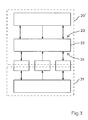
- Fig. 3 shows a system for data transmission between two microcomputer devices according to the prior art Known technology.
- FIG. 1 shows the functional units for a system for data transmission between two microcomputer devices. Only the components necessary for representing the system according to the invention are shown; the function of the respective microcomputer devices is not relevant for the description.
- the two microcomputer devices are arranged on a board common to both microcomputer devices.
- the first microcomputer device 1 contains at least the necessary components for data transmission with at least one second microcomputer device 2 .
- a first protocol controller 4 is connected to the microprocessor 2 contained in the first microcomputer device 1 via the so-called first microprocessor bus 3 .
- the first processor bus is implemented in parallel, usually containing address signals, control signals and data signals.
- the protocol controller 4 is a standard Ethernet controller, as has already been mentioned in the prior art. This first protocol controller 4 is able to output data to be transmitted serially via the serial data signals 5 according to the known Ethernet standard.
- the second microcomputer device 8 also contains a protocol controller 11 , which makes the received serial data signals 12 available as data for parallel access by the second access of the second microprocessor 9 via the second microprocessor bus 10 .
- the design of the second microprocessor bus 10 can differ from the first microprocessor bus 3 .
- the serial data signals 5 of the first are connected Microcomputer device 1 with the serial data signals 12 of the second microcomputer device via a galvanic isolation 7 , which is carried out, for example, with generally known optocouplers, magnetic couplers or capacitive couplers.
- the voltage supply area 6 of the first microcomputer device 1 can be constructed separately from the voltage supply area 13 of the second microcomputer device 2 .
- the data transmission from the second microcomputer device 2 to the first microcomputer device 1 takes place in the same way, but in the opposite direction.
- the opposite direction means that the data is transmitted from the second microcomputer device 8 to the first microcomputer device 1 , so that in this case the second microprocessor transfers the data to be transmitted to the second protocol controller 11 via its second microprocessor bus 10 , the second protocol controller 11 Controller 11 is able to transmit the data to be transmitted serially to the first microcomputer device 1 using the serial data signals 12 , 5 according to the known Ethernet standard, with or without electrical isolation 7.
- FIG. 2 shows an overview of a system for data transmission between more than two microcomputer devices.
- a superordinate microcomputer device 14 contains, in addition to the components relevant for its function and the components for data transmission described above, an Ethernet switch 15 described in the prior art and thus generally known. This Ethernet switch is used only to provide more than one serial data connection, so that a second microcomputer device 8 on the first serial data connection 16 and a third microcomputer device 18 on the second serial data connection 17 .
- one or more microcomputer devices can also be connected to one another with the aid of a cable 19 , for example a standard Ethernet cable.
- a cable 19 for example a standard Ethernet cable.
- the combination of spatially interconnected microcomputer devices and spatially distant microcomputer devices is also possible.
- FIG. 3 shows an example of a system for parallel data transmission between two microcomputer devices 20 , 21 in a parallel manner.
- a first microcomputer device 20 connected in parallel contains a so-called multiport RAM 22 for the data connection, which is written with the data to be transmitted and addressing information via the first port 23 during data transmission to the second microcomputer device 21 connected in parallel.
- the second microcomputer device 21 connected in parallel can read this data intended for it via the second port 24 of the multiport RAM 22 . It goes without saying that data transmission is also possible in the other direction, that is to say starting from the second microcomputer device 21 connected in parallel to the first microcomputer device 20 connected in parallel.
Landscapes
- Engineering & Computer Science (AREA)
- Computer Networks & Wireless Communication (AREA)
- Signal Processing (AREA)
- Information Transfer Systems (AREA)
- Communication Control (AREA)
- Small-Scale Networks (AREA)
Abstract
Description
- 1:
- erste Mikrocomputereinrichtung
- 2:
- erster Mikroprozessor
- 3:
- erster Mikroprozessorbus
- 4:
- erste Koppelvorrichtung, erster Protokoll-Controller
- 5:
- serielle Datensignale in der ersten Mikrocomputereinrichtung
- 6:
- Spannungsversorgungsbereich der ersten Mikrocomputereinrichtung
- 7:
- Galvanische Trennung
- 8:
- zweite Mikrocomputereinrichtung
- 9:
- zweiter Mikroprozessor
- 10:
- zweiter Mikroprozessorbus
- 11:
- zweite Koppelvorrichtung, zweiter Protokoll-Controller
- 12:
- serielle Datensignale in der zweiten Mikrocomputereinrichtung
- 13:
- Spannungsversorgungsbereich der zweiten Mikrocomputereinrichtung
- 14:
- übergeordnete Mikrocomputereinrichtung
- 15:
- Ethernet Switch
- 16:
- erste serielle Datenverbindung
- 17:
- zweite serielle Datenverbindung
- 18:
- dritte Mikrocomputereinrichtung
- 19:
- Kabel
- 20:
- erste parallel angeschlossene Mikrocomputereinrichtung
- 21:
- zweite parallel angeschlossene Mikrocomputereinrichtung
- 22:
- Multiport-RAM
- 23:
- erster Port
- 24:
- zweiter Port
Mikrocomputereinrichtung 1 mit den seriellen Datensignalen 12 der zweiten Mikrocomputereinrichtung über eine galvanische Trennung 7, welche beispielsweise mit allgemein bekannten Optokopplern, magnetischen Kopplern oder kapazitiven Kopplern erfolgt. Im Falle einer galvanischen Trennung der seriellen Datensignale 5, 12 kann der Spannungsversorgungsbereich 6 der ersten Mikrocomputereinrichtung 1 getrennt vom Spannungsversorgungsbereich 13 der zweiten Mikrocomputereinrichtung 2 aufgebaut werden. Die Datenübertragung von der zweiten Mikrocomputereinrichtung 2 zur ersten Mikrocomputereinrichtung 1 erfolgt dabei in der gleichen Art und Weise, jedoch in umgekehrter Richtung. In umgekehrter Richtung bedeutet, dass die Datenübertragung von der zweiten Mikrocomputereinrichtung 8 zur ersten Mikrocomputereinrichtung 1 erfolgt, so dass in diesem Falle der zweite Mikroprozessor die zu übertragenden Daten über seinen zweiten Mikroprozessorbus 10 an den zweiten Protokoll-Controller 11 übergibt, wobei der zweite Protokoll-Controller 11 ist in der Lage, die zu übertragenden Daten seriell über die seriellen Datensignale 12, 5 nach dem bekannten Ethernet-Standard an die erste Mikrocomputereinrichtung 1 zu übertragen, mit oder ohne galvanische Trennung 7.
Claims (11)
- System zur Datenübertragung zwischen Mikrocomputereinrichtungen (1, 8), welche jeweils mindestens einen Mikroprozessor (2, 9), einen Mikroprozessorbus (3, 10), daran angeschlossen eine Koppelvorrichtung (4, 11), die Koppelvorrichtung (4, 11) ein serielles Protokoll bereitstellt, enthalten, wobei die Datenübertragung zwischen den Mikrocomputereinrichtungen (1, 8) über die Koppelvorrichtungen erfolgt,
dadurch gekennzeichnet, dass die Mikrocomputereinrichtungen (1, 8) räumlich innerhalb eines Gerätes angeordnet sind und dass jede Mikrocomputereinrichtung (1, 8) jeweils einem eigenen, separaten Spannungsversorgungsbereich (6, 13) zugehört und die Koppelvorrichtungen (4, 11) ein standardisiertes serielles Protokoll bereitstellen. - System nach Anspruch 1,
dadurch gekennzeichnet, dass für die serielle Datenübertragung zwischen den Mikrocomputereinrichtungen (1, 8) das standardisierte serielle Ethernet Protokoll verwendet wird. - System nach Anspruch 1 oder 2,
dadurch gekennzeichnet, dass die Spannungsversorgungsbereiche (6, 13) der Mikrocomputereinrichtungen (1, 8) einzeln abschaltbar oder zuschaltbar sind und der jeweils verbleibende eingeschaltete Spannungsversorgungsbereich (6, 13) einer Mikrocomputereinrichtung (1, 8) unbeeinflusst bleibt. - System nach einem der Ansprüche 1 bis 3,
dadurch gekennzeichnet, dass die Mikrocomputereinrichtungen (1, 8) räumlich auf einem Board angeordnet sind. - System nach einem der Ansprüche 1 bis 4,
dadurch gekennzeichnet, dass zusätzlich zu den zwei miteinander datenübertragenden Mikrocomputereinrichtungen (14, 8) wenigstens eine weitere Mikrocomputereinrichtung (18) in das System eingefügt werden kann. - System nach einem der Ansprüche 1 bis 5,
dadurch gekennzeichnet, dass in wenigstens einer Mikrocomputereinrichtung (14) zur Ankopplung mehrerer weiterer Mikrocomputereinrichtungen (1, 18) ein Ethernet-Switch (15) verwendet wird. - System nach einem der Ansprüche 1 bis 6,
dadurch gekennzeichnet, dass mindestens eine Mikrocomputereinrichtung (18) räumlich entfernt über ein Kabel (19) mit der übergeordneten Mikrocomputereinrichtung (14) verbunden ist. - System nach einem der Ansprüche 1 bis 7,
dadurch gekennzeichnet,
und dass die serielle Datenverbindung (5, 12) zwischen den Mikrocomputereinrichtungen (1, 8) eine galvanische Trennung (7) enthält. - System nach Anspruch 8,
dadurch gekennzeichnet, dass die galvanische Trennung (7) mittels Optokoppler erfolgt. - System nach Anspruch 8,
dadurch gekennzeichnet, dass die galvanische Trennung (7) mittels magnetischer Koppler erfolgt. - System nach Anspruch 8,
dadurch gekennzeichnet, dass die galvanische Trennung (7) mittels kapazitiver Koppler erfolgt.
Applications Claiming Priority (2)
| Application Number | Priority Date | Filing Date | Title |
|---|---|---|---|
| DE10218037 | 2002-04-23 | ||
| DE10218037 | 2002-04-23 |
Publications (3)
| Publication Number | Publication Date |
|---|---|
| EP1363197A2 true EP1363197A2 (de) | 2003-11-19 |
| EP1363197A3 EP1363197A3 (de) | 2005-07-06 |
| EP1363197B1 EP1363197B1 (de) | 2008-09-10 |
Family
ID=28798701
Family Applications (1)
| Application Number | Title | Priority Date | Filing Date |
|---|---|---|---|
| EP03007718A Expired - Lifetime EP1363197B1 (de) | 2002-04-23 | 2003-04-04 | System zur Datenübertragung zwischen Mikrocomputereinrichtungen |
Country Status (5)
| Country | Link |
|---|---|
| US (1) | US7945715B2 (de) |
| EP (1) | EP1363197B1 (de) |
| AT (1) | ATE408193T1 (de) |
| DE (1) | DE50310461D1 (de) |
| ES (1) | ES2309249T3 (de) |
Families Citing this family (4)
| Publication number | Priority date | Publication date | Assignee | Title |
|---|---|---|---|---|
| US7644194B2 (en) * | 2003-07-14 | 2010-01-05 | Broadcom Corporation | Method and system for addressing a plurality of Ethernet controllers integrated into a single chip which utilizes a single bus interface |
| US20060265540A1 (en) * | 2005-05-17 | 2006-11-23 | Cardiac Pacemakers, Inc. | Method and apparatus for isolating universal serial bus (USB) communications link |
| JP5079342B2 (ja) * | 2007-01-22 | 2012-11-21 | ルネサスエレクトロニクス株式会社 | マルチプロセッサ装置 |
| US8030891B2 (en) | 2008-04-10 | 2011-10-04 | Smiths Medical Asd, Inc. | Ambulatory medical device with electrical isolation from connected peripheral device |
Family Cites Families (17)
| Publication number | Priority date | Publication date | Assignee | Title |
|---|---|---|---|---|
| US4358823A (en) * | 1977-03-25 | 1982-11-09 | Trw, Inc. | Double redundant processor |
| US4355354A (en) * | 1978-06-29 | 1982-10-19 | Standard Oil Company (Indiana) | Interface apparatus for coupling a minicomputer to a microcomputer for the transfer of data between them and method for using same |
| US4967377A (en) * | 1981-12-10 | 1990-10-30 | Canon Kabushiki Kaisha | Control system using computers and having an initialization function |
| US4590556A (en) * | 1983-01-17 | 1986-05-20 | Tandy Corporation | Co-processor combination |
| US5070450A (en) * | 1990-05-25 | 1991-12-03 | Dell Usa Corporation | Power on coordination system and method for multiple processors |
| US5253159A (en) * | 1991-06-28 | 1993-10-12 | Square D Company | Electrical distribution system having controller responsive to multiple command paths |
| US5598537A (en) * | 1994-03-25 | 1997-01-28 | Advanced Micro Devices, Inc. | Apparatus and method for driving a bus to a docking safe state in a dockable computer system including a docking station and a portable computer |
| JPH0876166A (ja) * | 1994-09-07 | 1996-03-22 | Nikon Corp | 不揮発メモリを有するシステム |
| US6901299B1 (en) * | 1996-04-03 | 2005-05-31 | Don Whitehead | Man machine interface for power management control systems |
| US6175854B1 (en) * | 1996-06-11 | 2001-01-16 | Ameritech Services, Inc. | Computer system architecture and method for multi-user, real-time applications |
| EP0886824A1 (de) * | 1996-12-13 | 1998-12-30 | Nyquist B.V. | Redundantes datenverarbeitungssystem mit zwei programmierbaren logiksteuergeräten in tandembetrieb |
| US6138174A (en) * | 1997-11-24 | 2000-10-24 | Rockwell Technologies, Llc | Industrial control system providing remote execution of graphical utility programs |
| US6728320B1 (en) * | 1999-09-23 | 2004-04-27 | Texas Instruments Incorporated | Capacitive data and clock transmission between isolated ICs |
| DE19961138C2 (de) | 1999-12-17 | 2001-11-22 | Siemens Ag | Multiport-RAM-Speichervorrichtung |
| DE10026416A1 (de) | 2000-05-29 | 2002-01-03 | Honeywell Ag | System zur Datenübertragung |
| US6742072B1 (en) * | 2000-08-31 | 2004-05-25 | Hewlett-Packard Development Company, Lp. | Method and apparatus for supporting concurrent system area network inter-process communication and I/O |
| GB2385984B (en) * | 2001-11-07 | 2006-06-28 | Micron Technology Inc | Semiconductor package assembly and method for electrically isolating modules |
-
2003
- 2003-04-04 ES ES03007718T patent/ES2309249T3/es not_active Expired - Lifetime
- 2003-04-04 DE DE50310461T patent/DE50310461D1/de not_active Expired - Lifetime
- 2003-04-04 AT AT03007718T patent/ATE408193T1/de active
- 2003-04-04 EP EP03007718A patent/EP1363197B1/de not_active Expired - Lifetime
- 2003-04-09 US US10/410,488 patent/US7945715B2/en not_active Expired - Lifetime
Also Published As
| Publication number | Publication date |
|---|---|
| US20030200376A1 (en) | 2003-10-23 |
| ATE408193T1 (de) | 2008-09-15 |
| ES2309249T3 (es) | 2008-12-16 |
| US7945715B2 (en) | 2011-05-17 |
| DE50310461D1 (de) | 2008-10-23 |
| EP1363197B1 (de) | 2008-09-10 |
| EP1363197A3 (de) | 2005-07-06 |
Similar Documents
| Publication | Publication Date | Title |
|---|---|---|
| DE4404962C2 (de) | Verfahren und Anordnung zum Konfigurieren von Funktionseinheiten in einer Master-Slave-Anordnung | |
| DE3486130T2 (de) | Uebertragungsleitungssteuerung. | |
| DE19581859B4 (de) | Steckverbinderanordnung zur Kopplung einer Einheit mit einem SCSI-Bus | |
| EP0019757B1 (de) | Datenverarbeitungsanlage, bei der mehrere Vorrechner und ein den Vorrechnern übergeordneter Hauptrechner in einer Baumstruktur angeordnet sind | |
| EP2948857B1 (de) | Busknoten und bussystem sowie verfahren zur identifikation der busknoten des bussystems | |
| DE69024111T2 (de) | Einrichtung und Verfahren zur Adresszuweisung an SCSI-unterstützte Peripheriegeräte | |
| DE3688778T2 (de) | Rückwandbus mit veränderlicher Länge. | |
| DE2944497C2 (de) | ||
| DE2313724A1 (de) | Elektronische datenverarbeitungsanlage | |
| DE2813418A1 (de) | Einrichtung in einer elektronischen datenverarbeitungsanlage zur meldung von fehler- und betriebszustaenden | |
| DE10302485B4 (de) | Feldbusanschaltung in Schaltanlagen | |
| DE69610874T2 (de) | Vorrichtung zur Datenübertragung zwischen einer Mehrzahl von Funktionsmodulen in einer lokalen Buseinheit und einem externen ARINC-629-Bus | |
| EP3575899B1 (de) | Automatisierungssystem, betriebsverfahren für automatisierungssystem und computerprogrammprodukt | |
| EP0290894B1 (de) | Verfahren zum Verteilen von aktuellen Adressentabellen in "n" ringförmigen Netzen | |
| EP1363197B1 (de) | System zur Datenübertragung zwischen Mikrocomputereinrichtungen | |
| DE3687047T2 (de) | Uebertragungsschaltung. | |
| WO2022038147A1 (de) | Modulare ein- und ausgabestation für ein industrielles automatisierungssystem und/oder industrielles iot-system | |
| DE102011004358B3 (de) | Verfahren zum Übertragen von Daten über einen synchronen seriellen Datenbus | |
| DE3688160T2 (de) | Interbussystem. | |
| DE102020115210B4 (de) | Steuersystem für ein mindestens zwei Übertragungsleitungen aufweisendes Bussystem | |
| EP1607810B1 (de) | Wartungsfähige elektrische Anlage | |
| EP1059835B1 (de) | Datenübermittlung zwischen Modulen eines elektrischen Geräts | |
| DE19640172A1 (de) | Übertrager-Leistungskopplung | |
| EP1629637B1 (de) | Übertragung von nachrichten in einem verteilten, zeitgesteuerten echtzeitsystem | |
| EP0728581A2 (de) | Bussystem für eine Druckmaschine |
Legal Events
| Date | Code | Title | Description |
|---|---|---|---|
| PUAI | Public reference made under article 153(3) epc to a published international application that has entered the european phase |
Free format text: ORIGINAL CODE: 0009012 |
|
| AK | Designated contracting states |
Kind code of ref document: A2 Designated state(s): AT BE BG CH CY CZ DE DK EE ES FI FR GB GR HU IE IT LI LU MC NL PT RO SE SI SK TR |
|
| AX | Request for extension of the european patent |
Extension state: AL LT LV MK |
|
| PUAL | Search report despatched |
Free format text: ORIGINAL CODE: 0009013 |
|
| AK | Designated contracting states |
Kind code of ref document: A3 Designated state(s): AT BE BG CH CY CZ DE DK EE ES FI FR GB GR HU IE IT LI LU MC NL PT RO SE SI SK TR |
|
| AX | Request for extension of the european patent |
Extension state: AL LT LV MK |
|
| RIC1 | Information provided on ipc code assigned before grant |
Ipc: 7G 05B 19/042 B Ipc: 7G 06F 13/38 A |
|
| 17P | Request for examination filed |
Effective date: 20060109 |
|
| AKX | Designation fees paid |
Designated state(s): AT BE BG CH CY CZ DE DK EE ES FI FR GB GR HU IE IT LI LU MC NL PT RO SE SI SK TR |
|
| 17Q | First examination report despatched |
Effective date: 20060908 |
|
| GRAP | Despatch of communication of intention to grant a patent |
Free format text: ORIGINAL CODE: EPIDOSNIGR1 |
|
| GRAS | Grant fee paid |
Free format text: ORIGINAL CODE: EPIDOSNIGR3 |
|
| GRAA | (expected) grant |
Free format text: ORIGINAL CODE: 0009210 |
|
| AK | Designated contracting states |
Kind code of ref document: B1 Designated state(s): AT BE BG CH CY CZ DE DK EE ES FI FR GB GR HU IE IT LI LU MC NL PT RO SE SI SK TR |
|
| REG | Reference to a national code |
Ref country code: GB Ref legal event code: FG4D Free format text: NOT ENGLISH |
|
| REG | Reference to a national code |
Ref country code: CH Ref legal event code: NV Representative=s name: BOVARD AG PATENTANWAELTE Ref country code: CH Ref legal event code: EP |
|
| REG | Reference to a national code |
Ref country code: IE Ref legal event code: FG4D Free format text: LANGUAGE OF EP DOCUMENT: GERMAN |
|
| REF | Corresponds to: |
Ref document number: 50310461 Country of ref document: DE Date of ref document: 20081023 Kind code of ref document: P |
|
| REG | Reference to a national code |
Ref country code: ES Ref legal event code: FG2A Ref document number: 2309249 Country of ref document: ES Kind code of ref document: T3 |
|
| PG25 | Lapsed in a contracting state [announced via postgrant information from national office to epo] |
Ref country code: SI Free format text: LAPSE BECAUSE OF FAILURE TO SUBMIT A TRANSLATION OF THE DESCRIPTION OR TO PAY THE FEE WITHIN THE PRESCRIBED TIME-LIMIT Effective date: 20080910 Ref country code: FI Free format text: LAPSE BECAUSE OF FAILURE TO SUBMIT A TRANSLATION OF THE DESCRIPTION OR TO PAY THE FEE WITHIN THE PRESCRIBED TIME-LIMIT Effective date: 20080910 |
|
| REG | Reference to a national code |
Ref country code: IE Ref legal event code: FD4D |
|
| PG25 | Lapsed in a contracting state [announced via postgrant information from national office to epo] |
Ref country code: IE Free format text: LAPSE BECAUSE OF FAILURE TO SUBMIT A TRANSLATION OF THE DESCRIPTION OR TO PAY THE FEE WITHIN THE PRESCRIBED TIME-LIMIT Effective date: 20080910 Ref country code: BG Free format text: LAPSE BECAUSE OF FAILURE TO SUBMIT A TRANSLATION OF THE DESCRIPTION OR TO PAY THE FEE WITHIN THE PRESCRIBED TIME-LIMIT Effective date: 20081210 |
|
| PG25 | Lapsed in a contracting state [announced via postgrant information from national office to epo] |
Ref country code: CZ Free format text: LAPSE BECAUSE OF FAILURE TO SUBMIT A TRANSLATION OF THE DESCRIPTION OR TO PAY THE FEE WITHIN THE PRESCRIBED TIME-LIMIT Effective date: 20080910 Ref country code: RO Free format text: LAPSE BECAUSE OF FAILURE TO SUBMIT A TRANSLATION OF THE DESCRIPTION OR TO PAY THE FEE WITHIN THE PRESCRIBED TIME-LIMIT Effective date: 20080910 Ref country code: PT Free format text: LAPSE BECAUSE OF FAILURE TO SUBMIT A TRANSLATION OF THE DESCRIPTION OR TO PAY THE FEE WITHIN THE PRESCRIBED TIME-LIMIT Effective date: 20090210 Ref country code: SK Free format text: LAPSE BECAUSE OF FAILURE TO SUBMIT A TRANSLATION OF THE DESCRIPTION OR TO PAY THE FEE WITHIN THE PRESCRIBED TIME-LIMIT Effective date: 20080910 |
|
| PLBE | No opposition filed within time limit |
Free format text: ORIGINAL CODE: 0009261 |
|
| STAA | Information on the status of an ep patent application or granted ep patent |
Free format text: STATUS: NO OPPOSITION FILED WITHIN TIME LIMIT |
|
| PG25 | Lapsed in a contracting state [announced via postgrant information from national office to epo] |
Ref country code: EE Free format text: LAPSE BECAUSE OF FAILURE TO SUBMIT A TRANSLATION OF THE DESCRIPTION OR TO PAY THE FEE WITHIN THE PRESCRIBED TIME-LIMIT Effective date: 20080910 Ref country code: DK Free format text: LAPSE BECAUSE OF FAILURE TO SUBMIT A TRANSLATION OF THE DESCRIPTION OR TO PAY THE FEE WITHIN THE PRESCRIBED TIME-LIMIT Effective date: 20080910 |
|
| 26N | No opposition filed |
Effective date: 20090611 |
|
| PG25 | Lapsed in a contracting state [announced via postgrant information from national office to epo] |
Ref country code: SE Free format text: LAPSE BECAUSE OF FAILURE TO SUBMIT A TRANSLATION OF THE DESCRIPTION OR TO PAY THE FEE WITHIN THE PRESCRIBED TIME-LIMIT Effective date: 20081210 |
|
| PG25 | Lapsed in a contracting state [announced via postgrant information from national office to epo] |
Ref country code: MC Free format text: LAPSE BECAUSE OF NON-PAYMENT OF DUE FEES Effective date: 20090430 |
|
| PG25 | Lapsed in a contracting state [announced via postgrant information from national office to epo] |
Ref country code: GR Free format text: LAPSE BECAUSE OF FAILURE TO SUBMIT A TRANSLATION OF THE DESCRIPTION OR TO PAY THE FEE WITHIN THE PRESCRIBED TIME-LIMIT Effective date: 20081211 |
|
| REG | Reference to a national code |
Ref country code: CH Ref legal event code: PFA Owner name: PHOENIX CONTACT GMBH & CO. KG Free format text: PHOENIX CONTACT GMBH & CO. KG#FLACHSMARKTSTRASSE 8#32825 BLOMBERG (DE) -TRANSFER TO- PHOENIX CONTACT GMBH & CO. KG#FLACHSMARKTSTRASSE 8#32825 BLOMBERG (DE) |
|
| PG25 | Lapsed in a contracting state [announced via postgrant information from national office to epo] |
Ref country code: LU Free format text: LAPSE BECAUSE OF NON-PAYMENT OF DUE FEES Effective date: 20090404 |
|
| PG25 | Lapsed in a contracting state [announced via postgrant information from national office to epo] |
Ref country code: HU Free format text: LAPSE BECAUSE OF FAILURE TO SUBMIT A TRANSLATION OF THE DESCRIPTION OR TO PAY THE FEE WITHIN THE PRESCRIBED TIME-LIMIT Effective date: 20090311 |
|
| PG25 | Lapsed in a contracting state [announced via postgrant information from national office to epo] |
Ref country code: TR Free format text: LAPSE BECAUSE OF FAILURE TO SUBMIT A TRANSLATION OF THE DESCRIPTION OR TO PAY THE FEE WITHIN THE PRESCRIBED TIME-LIMIT Effective date: 20080910 |
|
| PG25 | Lapsed in a contracting state [announced via postgrant information from national office to epo] |
Ref country code: CY Free format text: LAPSE BECAUSE OF FAILURE TO SUBMIT A TRANSLATION OF THE DESCRIPTION OR TO PAY THE FEE WITHIN THE PRESCRIBED TIME-LIMIT Effective date: 20080910 |
|
| REG | Reference to a national code |
Ref country code: FR Ref legal event code: PLFP Year of fee payment: 14 |
|
| PGFP | Annual fee paid to national office [announced via postgrant information from national office to epo] |
Ref country code: NL Payment date: 20160421 Year of fee payment: 14 |
|
| PGFP | Annual fee paid to national office [announced via postgrant information from national office to epo] |
Ref country code: ES Payment date: 20160422 Year of fee payment: 14 Ref country code: CH Payment date: 20160423 Year of fee payment: 14 Ref country code: GB Payment date: 20160425 Year of fee payment: 14 |
|
| PGFP | Annual fee paid to national office [announced via postgrant information from national office to epo] |
Ref country code: AT Payment date: 20160426 Year of fee payment: 14 Ref country code: FR Payment date: 20160423 Year of fee payment: 14 Ref country code: BE Payment date: 20160421 Year of fee payment: 14 Ref country code: IT Payment date: 20160429 Year of fee payment: 14 |
|
| REG | Reference to a national code |
Ref country code: CH Ref legal event code: PL |
|
| REG | Reference to a national code |
Ref country code: NL Ref legal event code: MM Effective date: 20170501 |
|
| REG | Reference to a national code |
Ref country code: AT Ref legal event code: MM01 Ref document number: 408193 Country of ref document: AT Kind code of ref document: T Effective date: 20170404 |
|
| GBPC | Gb: european patent ceased through non-payment of renewal fee |
Effective date: 20170404 |
|
| REG | Reference to a national code |
Ref country code: FR Ref legal event code: ST Effective date: 20171229 |
|
| PG25 | Lapsed in a contracting state [announced via postgrant information from national office to epo] |
Ref country code: AT Free format text: LAPSE BECAUSE OF NON-PAYMENT OF DUE FEES Effective date: 20170404 Ref country code: NL Free format text: LAPSE BECAUSE OF NON-PAYMENT OF DUE FEES Effective date: 20170501 Ref country code: FR Free format text: LAPSE BECAUSE OF NON-PAYMENT OF DUE FEES Effective date: 20170502 |
|
| PG25 | Lapsed in a contracting state [announced via postgrant information from national office to epo] |
Ref country code: CH Free format text: LAPSE BECAUSE OF NON-PAYMENT OF DUE FEES Effective date: 20170430 Ref country code: GB Free format text: LAPSE BECAUSE OF NON-PAYMENT OF DUE FEES Effective date: 20170404 Ref country code: LI Free format text: LAPSE BECAUSE OF NON-PAYMENT OF DUE FEES Effective date: 20170430 |
|
| REG | Reference to a national code |
Ref country code: BE Ref legal event code: MM Effective date: 20170430 |
|
| PG25 | Lapsed in a contracting state [announced via postgrant information from national office to epo] |
Ref country code: IT Free format text: LAPSE BECAUSE OF NON-PAYMENT OF DUE FEES Effective date: 20170404 Ref country code: BE Free format text: LAPSE BECAUSE OF NON-PAYMENT OF DUE FEES Effective date: 20170430 |
|
| REG | Reference to a national code |
Ref country code: ES Ref legal event code: FD2A Effective date: 20180626 |
|
| PG25 | Lapsed in a contracting state [announced via postgrant information from national office to epo] |
Ref country code: ES Free format text: LAPSE BECAUSE OF NON-PAYMENT OF DUE FEES Effective date: 20170405 |
|
| PGFP | Annual fee paid to national office [announced via postgrant information from national office to epo] |
Ref country code: DE Payment date: 20200629 Year of fee payment: 18 |
|
| REG | Reference to a national code |
Ref country code: DE Ref legal event code: R119 Ref document number: 50310461 Country of ref document: DE |
|
| PG25 | Lapsed in a contracting state [announced via postgrant information from national office to epo] |
Ref country code: DE Free format text: LAPSE BECAUSE OF NON-PAYMENT OF DUE FEES Effective date: 20211103 |