EP1363079A1 - Türscharnier sowie Haushaltsgerätetür - Google Patents
Türscharnier sowie Haushaltsgerätetür Download PDFInfo
- Publication number
- EP1363079A1 EP1363079A1 EP03009257A EP03009257A EP1363079A1 EP 1363079 A1 EP1363079 A1 EP 1363079A1 EP 03009257 A EP03009257 A EP 03009257A EP 03009257 A EP03009257 A EP 03009257A EP 1363079 A1 EP1363079 A1 EP 1363079A1
- Authority
- EP
- European Patent Office
- Prior art keywords
- door
- locking
- locking element
- hinge part
- closing
- Prior art date
- Legal status (The legal status is an assumption and is not a legal conclusion. Google has not performed a legal analysis and makes no representation as to the accuracy of the status listed.)
- Withdrawn
Links
Images



Classifications
-
- F—MECHANICAL ENGINEERING; LIGHTING; HEATING; WEAPONS; BLASTING
- F24—HEATING; RANGES; VENTILATING
- F24C—DOMESTIC STOVES OR RANGES ; DETAILS OF DOMESTIC STOVES OR RANGES, OF GENERAL APPLICATION
- F24C15/00—Details
- F24C15/02—Doors specially adapted for stoves or ranges
- F24C15/023—Mounting of doors, e.g. hinges, counterbalancing
-
- E—FIXED CONSTRUCTIONS
- E05—LOCKS; KEYS; WINDOW OR DOOR FITTINGS; SAFES
- E05F—DEVICES FOR MOVING WINGS INTO OPEN OR CLOSED POSITION; CHECKS FOR WINGS; WING FITTINGS NOT OTHERWISE PROVIDED FOR, CONCERNED WITH THE FUNCTIONING OF THE WING
- E05F1/00—Closers or openers for wings, not otherwise provided for in this subclass
- E05F1/08—Closers or openers for wings, not otherwise provided for in this subclass spring-actuated, e.g. for horizontally sliding wings
- E05F1/10—Closers or openers for wings, not otherwise provided for in this subclass spring-actuated, e.g. for horizontally sliding wings for swinging wings, e.g. counterbalance
- E05F1/12—Mechanisms in the shape of hinges or pivots, operated by springs
- E05F1/1246—Mechanisms in the shape of hinges or pivots, operated by springs with a coil spring perpendicular to the pivot axis
- E05F1/1269—Mechanisms in the shape of hinges or pivots, operated by springs with a coil spring perpendicular to the pivot axis with a traction spring
- E05F1/1276—Mechanisms in the shape of hinges or pivots, operated by springs with a coil spring perpendicular to the pivot axis with a traction spring for counterbalancing
-
- E—FIXED CONSTRUCTIONS
- E05—LOCKS; KEYS; WINDOW OR DOOR FITTINGS; SAFES
- E05Y—INDEXING SCHEME ASSOCIATED WITH SUBCLASSES E05D AND E05F, RELATING TO CONSTRUCTION ELEMENTS, ELECTRIC CONTROL, POWER SUPPLY, POWER SIGNAL OR TRANSMISSION, USER INTERFACES, MOUNTING OR COUPLING, DETAILS, ACCESSORIES, AUXILIARY OPERATIONS NOT OTHERWISE PROVIDED FOR, APPLICATION THEREOF
- E05Y2800/00—Details, accessories and auxiliary operations not otherwise provided for
- E05Y2800/20—Combinations of elements
- E05Y2800/22—Combinations of elements of not identical elements of the same category, e.g. combinations of not identical springs
-
- E—FIXED CONSTRUCTIONS
- E05—LOCKS; KEYS; WINDOW OR DOOR FITTINGS; SAFES
- E05Y—INDEXING SCHEME ASSOCIATED WITH SUBCLASSES E05D AND E05F, RELATING TO CONSTRUCTION ELEMENTS, ELECTRIC CONTROL, POWER SUPPLY, POWER SIGNAL OR TRANSMISSION, USER INTERFACES, MOUNTING OR COUPLING, DETAILS, ACCESSORIES, AUXILIARY OPERATIONS NOT OTHERWISE PROVIDED FOR, APPLICATION THEREOF
- E05Y2900/00—Application of doors, windows, wings or fittings thereof
- E05Y2900/30—Application of doors, windows, wings or fittings thereof for domestic appliances
- E05Y2900/308—Application of doors, windows, wings or fittings thereof for domestic appliances for ovens
Definitions
- the present invention relates to a door hinge and a door for closing a Usable space of a household appliance that can be pivoted horizontally via the door hinge the household appliance is stored.
- the door hinge has a pivotable on the door side Hinge part, a fixed hinge part on the household appliance side, a closing spring for Exerting a spring force acting against the weight of the door on the door and an adjustable locking element.
- the locking element secures in a first locking position the door in a first swivel position against the spring force Conclude.
- the hinge has a frame that can be firmly connected to the oven hatch, and a lever that is outside of the frame extends to engage a seat which is laterally the opening of the Cooker is trained.
- the hinge also has elastic means that the Counteract the swiveling movement of the furnace flap.
- On a middle section of the Lever is a blocking device or a locking element pivoted, the can be pressed against an edge of an opening provided in the frame to keep the oven hatch in a partially open pivot position.
- the object of the present invention is a door hinge or a door for closing a usable space of a household appliance, in particular a cooking appliance To provide, in which the door in a structurally simple manner in an additional Swivel position can be locked.
- the object of the invention is through a door with the features of claim 1 and solved by a door hinge with the features of claim 13.
- the locking element Door not only in a first swivel position, but also in a second Secure swivel position.
- the locking element is in a second locking position adjusted.
- the door In the second locking position, the door is in a pivot position relative to the first different second pivot position against the spring force against automatic closing secured.
- the opening angle of the first swivel position can for example, be suitably designed for door removal.
- the opening angle of the second Swivel position can be particularly suitable to keep the door in a grill position to keep.
- the invention that is to secure a pivoting position anyway Door locking element used to add the second Secure the swivel position of the door. Other holding mechanisms to secure the second pivoting position of the door is therefore not necessary.
- the Door in the additional swivel position in a stable end position, i.e. one The door is open.
- a is advantageous Prevents pivoting of the door in both pivoting directions.
- the door is thus fixed in their open position. Due to the fixed door is a handling of the door especially during a cleaning process by the operator simplified.
- the locking element has a first locking stop, which in the first locking position of the locking element holds the door in the first pivot position. This ensures that the door is reliably in its first swivel position automatic closing is ensured. Locking the door in the first Swivel position can also serve as an assembly aid for unhooking the door.
- the locking element can be an additional second Have locking stop.
- the second stop stops in the second Locking position of the locking element, the door in the second pivot position.
- first and second locking stops common counter-stop on the door side is assigned. Depending on the position of the Bolt element can thus one of the two locking stops on the door side Trigger the counter stop. An additional second counterstop on the door is therefore unnecessary.
- the locking element in an additional locking position stationary hinge part of the door hinge locked on the household appliance.
- the locking element according to the invention can thus in three different ways Positions, namely the two locking positions and the locking position three perform different functions.
- the locking element at the same time in the locking position with a counter stop can be brought in to lock the door on the home appliance.
- the door hinge has a locking element.
- the Locking element is engaged in at least one of the locking or locking positions can be brought with the locking element, whereby the locking element can be positioned in the correct position.
- the door has a removable door inner pane.
- the opening angle of the additional second pivot position can be designed such that removal of the Inner door pane in the second secured pivot position possible in a simple manner is.
- an expansion path of the inner door pane is independent from an adjustment path of the locking element. This can advantageously be the locking element brought into the second locking position even before the door inner pane is removed become. The door is therefore already against a before the removal of the inner door pane automatic closing is ensured.
- the inner door pane can be locked with the locking element interact that when removing the inner door pane that Locking element adjusted into a locking position. This is when the Door inner pane automatically ensures that the door counteracts the spring force of the Closing spring is secured against automatic closing.
- a cooking appliance 1 with a cooking appliance door 3 is shown in dash-dot line Closing of a cooking space 5 is indicated schematically.
- the door 3 is between one in the open position shown in Figure 1 and a closed position in which the Cooking chamber 5 is closed.
- the door 3 has an inner door pane 7 and a door outer pane 9, both of which are attached to a door frame 11.
- the outer pane 9 is glued to the door frame 11.
- the inner pane 7 is releasably on the door frame 11, for example via a latching connection, not shown attached.
- the door frame 11 has the Cooking chamber 5 side facing a passage opening 13.
- the fixed hinge part 15 is in one on the cooking device-side receiving part 19.
- the receiving part 19 is in the cooking device provided on both sides of a front opening of the cooking space 5.
- the Door hinge 17 has a fixed hinge part 15 in addition to the housing door-side movable hinge part 21, which is fastened within the door frame 11 is.
- the movable hinge part 21 is a frame-like elongated shaped element a U-shaped cross section. Two opposite legs 23 of the hinge part 21 are connected to one another via a rear wall 25. Both the mobile Hinge part 21 as well as the fixed hinge part 15 are in a known manner from one bent steel sheet.
- the fixed hinge part 15 is made of two of the same Pieces composed of stamped sheet steel, for example by rivets or welding are firmly joined together.
- a pin 27 is attached, which is extends between the legs 23 of the door-side hinge part 21.
- the fixed hinge part 15 is mounted on the pin 27 4.
- the pin 27 thus serves as a hinge axis for the movable hinge part 21.
- the fixed hinge part 15 is essentially L-shaped according to FIGS. 1 and 4 with two end legs 29, 31 educated.
- the first end leg 29 of the fixed hinge part 15 is on the Pin 27 supported.
- the second end leg 31 of the fixed hinge part 15 extends through an opening 33 in the rear wall 25 of the door-side hinge part 21 and reaches into the interior of the receiving part on the appliance side according to FIGS. 1 and 4 19th
- a spring device is described below with reference to FIGS. 3 and 4 acts against the weight of the door 3 acting spring force on the door 3.
- the Spring device has a coil spring or closing spring 35 which with its the upper end is supported on a rivet 37.
- the rivet 37 connects the two opposite legs 23 on the upper edge of the hinge part 21.
- the lower The end of the coil spring 35 is engaged with a pin 39.
- the pin 39 is on two opposite arms 41 of a bracket 43 mounted.
- the bracket arms 41 extend on both sides of the fixed hinge part 15.
- the two are via a pin 45 opposite bracket arms 41 connected to the fixed hinge part 15.
- the Pin 45 thus represents a point of application for the spring force of the closing spring 35
- the position of the pin 45 results in a lever arm h according to FIG Hinge axis of the pin 27.
- the lever arm h causes a moment that counter the weight of the door 3 acts.
- Carrier part 47 is arranged pivotably about a horizontal axis via a pin 48.
- the Carrier part 47 carries a cam follower roller 49, which with a cam edge 51 of the stationary Hinge part 15 cooperates.
- the carrier part 47 is in by means of a compression spring 53 in Biased towards the cam edge 51 of the fixed hinge part 15.
- compression spring 53 is supported on a crosspiece 55, which is between the two opposite bracket arms 41 is attached.
- the special contour of the Cam edge 51 of the fixed hinge part 15 does the following: When moving the door 3 from the closed position and in the closed position must first Spring force of the compression spring 53 pressing on the cam follower roller 49 is overcome become.
- the door 3 is in its closed position on the one hand in a stable end position held.
- the door 3 - if, for example, from its open position is struck unintentionally - braked due to the spring force of the compression spring 53.
- the second end leg 31 of the fixed hinge part 15 is in Engagement with the receiving part 19 on the cooking appliance.
- the second end leg has 31 has a notch 57 shown in FIG. 1 on its lower side. at hung door 3, the notch 57 lies on a lower opening edge 59 of the Receiving part 19.
- the second end leg 31 abuts one Stop 59 of the receiving part 19, whereby the stationary hinge part 15 stably in the door-side receiving part 19 is hooked.
- a rotary latch 61 is pivotally articulated via a pivot pin 62.
- the rotary latch 61 has a semicircular depression 63.
- the Recess 63 serves as a first locking stop 63.
- One of pivot 62 removed end face 65 of the rotary latch 61 serves as a second locking stop.
- the function of the two locking stops 63, 65 is described below with reference to FIG. 1 explained.
- the rotary latch 61 is both in a dash-dotted line in a first Locking position I and in a solid line in a second locking position II shown.
- the rotary latch 61 abuts the first Locking stop 63 against a counter-stop 65 on the door.
- the door 3 is thus in a first pivot position against the spring force of the coil spring 39 against automatic closing secured.
- This first pivot position can be, for example Operator as an assembly aid for unhooking the fixed hinge part 15 from the serve on the appliance side receiving part 19.
- the counter stop 65 is used according to the figure 1 the opening edge of the opening 33 in the rear wall 25 of the door-side hinge part 21.
- the rotary latch 61 can move from the first locking position I clockwise by 90 ° into the second locking position II can be pivoted. As a result, comes across in the second Locking position II, the second locking stop 65 on the end face against the counter stop 65.
- the door 3 is thus in a second pivot position against the spring force of the Coil spring 39 secured against automatic closing. According to the invention therefore the door in two different pivot positions or in two different opening angles can be secured.
- the second pivot position corresponds to the open position of the door 3. This gives the operator free and easy access to the inner door pane 7 the door.
- the second pivoting position of the door 3 is therefore a simple removal of the Inner pane 7 from door 3 possible.
- Weight of the door reduced accordingly. Due to the reduced weight tends the door to an automatic closing.
- the automatic closing of door 3 is however advantageously prevented when the rotary latch 61 is in the second locking position II located.
- the rotary latch 61 can be brought into a locking position III, which in the figure 2 is indicated.
- the rotary latch 61 is from its first locking position I in Counterclockwise pivoted about 90 °.
- the second comes at the front Locking stop 65 in contact with a counter stop 67 on the cooking appliance side Receiving part 19, whereby the door 3 is locked on the cooking device.
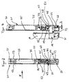
- FIGS. 5 and 6 A lower section of the door 3 is shown enlarged in FIGS. 5 and 6.
- the receiving part 19 on the cooking appliance side is only indicated by dash-dotted lines. Accordingly, protrudes the fixed pivot part 15 together with the rotary latch 61 through the Passage opening 13 of the door frame 11.
- the first locking stop 63 is in contact with the Counter stop 69 on the door side.
- the second locking stop 65 is in contact with the door side Counter stop 65, whereby the door 3 in its substantially horizontal open position is held.
- arrow A also shows an expansion path for the inner window pane 11 indicated.
- the inner pane 7 is approximately perpendicular to the door frame 11 detachable from this.
- the arrow V indicates an adjustment path of the rotary latch 61 between the first and second locking positions I, II and the locking position III.
- the expansion path A of the inner door panel 7 is independent of the adjustment path V of the rotary latch 61.
Landscapes
- Engineering & Computer Science (AREA)
- Chemical & Material Sciences (AREA)
- Combustion & Propulsion (AREA)
- Mechanical Engineering (AREA)
- General Engineering & Computer Science (AREA)
- Electric Ovens (AREA)
Abstract
Description
Claims (13)
- Tür zum Verschließen eines Nutzraumes (5) eines Haushaltsgerätes (1), insbesondere eines Gargerätes, die über zumindest ein Türscharnier (17) horizontal schwenkbar an dem Haushaltsgerät (1) gelagert ist, welches Türscharnier (17) einen türseitigen schwenkbaren Scharnierteil (21), einen haushaltsgeräteseitigen ortsfesten Scharnierteil (15), eine Schließfeder (35) zur Ausübung einer entgegen der Gewichtskraft der Tür wirkenden Federkraft auf die Tür und ein verstellbares Riegelelement (61) aufweist, das in einer ersten Arretierposition (I) die Tür in einer ersten Schwenkstellung entgegen der Federkraft gegen Schließen sichert, dadurch gekennzeichnet, dass das Riegelelement (61) in einer zusätzlichen zweiten Arretierposition (II) die Tür in einer zur ersten Schwenkstellung unterschiedlichen zweiten Schwenkstellung entgegen der Federkraft gegen ein selbsttätiges Schließen sichert.
- Tür nach Anspruch 1, dadurch gekennzeichnet, dass die Tür in der zusätzlichen zweiten Schwenkstellung in einer stabilen Endlage ist.
- Tür nach Anspruch 1 oder 2, dadurch gekennzeichnet, dass das Riegelelement (61) einen ersten Arretieranschlag (63) aufweist, der in der ersten Arretierposition (I) des Riegelelements (61) die Tür in der ersten Schwenkstellung hält.
- Tür nach einem der vorhergehenden Ansprüche, dadurch gekennzeichnet, dass das Riegelelement (61) einen zweiten Arretieranschlag (65) aufweist, der in der zweiten Arretierposition (II) des Riegelelements (61) die Tür in der zweiten Schwenkstellung hält.
- Tür nach Anspruch 4, dadurch gekennzeichnet, dass dem ersten und zweiten Arretieranschlag (63, 65) ein gemeinsamer türseitiger Gegenanschlag (69) zugeordnet ist, und dass je nach Position des Riegelelements (61) einer der beiden Arretieranschläge (59, 67) mit dem türseitigen Gegenanschlag (69) in Anlage ist.
- Tür nach einem der vorhergehenden Ansprüche, dadurch gekennzeichnet, dass das Riegelelement (61) in einer zusätzlichen Verriegelungsposition (III) das ortsfeste Scharnierteil (15) des Türscharniers an dem Haushaltsgerät verriegelt.
- Tür nach Anspruch 6, dadurch gekennzeichnet, dass der zweite Arretieranschlag (65) des Riegelelements (61) in der Verriegelungsposition (III) mit einem haushaltsgeräteseitigen Gegenanschlag (67) in Anlage ist zur Verriegelung des ortsfesten Scharnierteiles an dem Haushaltsgerät.
- Tür nach einem der vorhergehenden Ansprüche, dadurch gekennzeichnet, dass das Türscharnier (17) zumindest ein mit dem Riegelelement (61) zusammenwirkendes Rastelement (68) aufweist, mit dem das Riegelelement (61) in der ersten Arretierposition (I), der zweiten Arretierposition (II) oder in der Verriegelungsposition (III) in Eingriff ist.
- Tür nach einem der vorhergehenden Ansprüche, dadurch gekennzeichnet, dass die Tür eine entnehmbare Türinnenscheibe (7) aufweist.
- Tür nach Anspruch 9, dadurch gekennzeichnet, dass die Türinnenscheibe mit dem Riegelelement derart zusammenwirkt, dass bei der Entnahme der Türinnenscheibe sich das Riegelelement in die zweite Arretierposition verstellt, wodurch bei der Entnahme der Türinnenscheibe die Tür automatisch entgegen der Federkraft der Schließfeder gegen ein selbsttätiges Schließen gesichert ist.
- Tür nach Anspruch 9, dadurch gekennzeichnet, dass ein Ausbauweg (A) der Türinnenscheibe (7) unabhängig ist von einem Verstellweg (V) des Riegelelements (61), so dass bereits vor der Entnahme der Türinnenscheibe (7) die Tür in der zweiten Schwenkstellung gegen ein selbsttätiges Schließen gesichert ist.
- Haushaltsgerät mit einer Tür nach einem der vorhergehenden Ansprüche.
- Türscharnier für eine Tür zum Verschließen eines Nutzraums (5) eines Haushaltsgerätes (1), insbesondere eines Gargerätes mit einem haushaltsgeräteseitigen ortsfesten Scharnierteil (15), an dem ein türseitiger schwenkbarer Scharnierteil (21) zwischen einer Offenstellung und einer Schließstellung schwenkbar gelagert ist, und mit einer Schließfeder (35), die das schwenkbare Scharnierteil (21) in die Schließstellung vorspannt, welches Türscharnier (17) ein verstellbares Riegelelement (61) aufweist, das in einer ersten Arretierposition (I) das schwenkbare Scharnierteil (21) gegenüber dem ortsfesten Scharnierteil (15) entgegen der Federkraft der Schließfeder (35) in einer ersten Schwenkstellung gegen Schließen sichert, dadurch gekennzeichnet, dass das Riegelelement (61) in einer zusätzlichen zweiten Arretierposition (II) das schwenkbare Scharnierteil (21) in einer zur ersten Schwenkstellung unterschiedlichen zweiten Schwenkstellung gegenüber dem haushaltsgeräteseitigen Scharnierteil (15) entgegen der Federkraft sichert.
Applications Claiming Priority (2)
| Application Number | Priority Date | Filing Date | Title |
|---|---|---|---|
| DE10218101A DE10218101A1 (de) | 2002-04-23 | 2002-04-23 | Türscharnier sowie Haushaltsgerätetür |
| DE10218101 | 2002-04-23 |
Publications (1)
| Publication Number | Publication Date |
|---|---|
| EP1363079A1 true EP1363079A1 (de) | 2003-11-19 |
Family
ID=29264784
Family Applications (1)
| Application Number | Title | Priority Date | Filing Date |
|---|---|---|---|
| EP03009257A Withdrawn EP1363079A1 (de) | 2002-04-23 | 2003-04-23 | Türscharnier sowie Haushaltsgerätetür |
Country Status (2)
| Country | Link |
|---|---|
| EP (1) | EP1363079A1 (de) |
| DE (1) | DE10218101A1 (de) |
Cited By (1)
| Publication number | Priority date | Publication date | Assignee | Title |
|---|---|---|---|---|
| FR2906869A1 (fr) * | 2006-10-05 | 2008-04-11 | Brandt Ind Sas | Dispositif de blocage d'une porte de four de cuisson domestique |
Families Citing this family (1)
| Publication number | Priority date | Publication date | Assignee | Title |
|---|---|---|---|---|
| DE102019211686A1 (de) * | 2019-08-05 | 2021-02-11 | BSH Hausgeräte GmbH | Einbauhaushaltsgerät mit einer Befestigungsplatte |
Citations (3)
| Publication number | Priority date | Publication date | Assignee | Title |
|---|---|---|---|---|
| US3453996A (en) * | 1967-09-26 | 1969-07-08 | Charles W Agee | Oven door hinge assembly |
| US4817240A (en) * | 1983-06-03 | 1989-04-04 | Ace Manufacturing Co. | Appliance door hinge |
| DE19824148A1 (de) * | 1997-05-30 | 1998-12-03 | Brera Cerniere S R I | Scharnier für Ofenklappen von Elektro-, Gas- und Mikrowellenherden oder ähnlichen Geräten |
-
2002
- 2002-04-23 DE DE10218101A patent/DE10218101A1/de not_active Withdrawn
-
2003
- 2003-04-23 EP EP03009257A patent/EP1363079A1/de not_active Withdrawn
Patent Citations (3)
| Publication number | Priority date | Publication date | Assignee | Title |
|---|---|---|---|---|
| US3453996A (en) * | 1967-09-26 | 1969-07-08 | Charles W Agee | Oven door hinge assembly |
| US4817240A (en) * | 1983-06-03 | 1989-04-04 | Ace Manufacturing Co. | Appliance door hinge |
| DE19824148A1 (de) * | 1997-05-30 | 1998-12-03 | Brera Cerniere S R I | Scharnier für Ofenklappen von Elektro-, Gas- und Mikrowellenherden oder ähnlichen Geräten |
Cited By (1)
| Publication number | Priority date | Publication date | Assignee | Title |
|---|---|---|---|---|
| FR2906869A1 (fr) * | 2006-10-05 | 2008-04-11 | Brandt Ind Sas | Dispositif de blocage d'une porte de four de cuisson domestique |
Also Published As
| Publication number | Publication date |
|---|---|
| DE10218101A1 (de) | 2003-11-20 |
Similar Documents
| Publication | Publication Date | Title |
|---|---|---|
| DE19801721C1 (de) | Schubstangenverschluß | |
| EP1548366A2 (de) | Türscharnier für eine Tür eines Haushaltsgeräts | |
| EP2096360A2 (de) | Haushaltsgerätetür und Verfahren zum Bedienen der Haushaltsgerätetür | |
| EP3621483B1 (de) | Haltevorrichtung für eine frontblende einer schublade | |
| EP2762660A2 (de) | Riegelaufnahmeteil | |
| EP3021047B1 (de) | Tür für ein haushaltsgerät und haushaltsgerät | |
| DE102012021008B3 (de) | Schnäpperschloss, insbesondere als Zusatzverriegelung einer Tür, eines Tors oder eines Fensters | |
| EP3621482B1 (de) | Haltevorrichtung für eine frontblende einer schublade | |
| DE9406610U1 (de) | Backofen | |
| EP2741015B1 (de) | Tür für ein Haushaltsgerät mit einem plattenartigen Greifteil und einem Greifteilöffner, Haushaltsgerät mit einer derartigen Tür sowie Verfahren zum Öffnen einer Tür eines Haushaltsgeräts | |
| DE2458800C2 (de) | Schnappvorrichtung | |
| EP1599650B1 (de) | Verschlusseinrichtung für die tür von grossküchengeräten | |
| DE19923994A1 (de) | Hausgerät-Scharniervorrichtung | |
| DE10218101A1 (de) | Türscharnier sowie Haushaltsgerätetür | |
| DE19902579C2 (de) | Verschlußvorrichtung für den unterschlagenden Flügel zweiflügeliger setzholzloser Fenster oder Türen | |
| EP4571020A1 (de) | Schloss mit schwenkriegel | |
| EP3688260B1 (de) | In der kippstellung verrastbarer und dennoch beim schieb-schliessen leicht bewegbarer beschlag für ein fenster oder eine tür | |
| DE10031688A1 (de) | Blende für Möbel | |
| DE3243865C2 (de) | Türscharnier für Haushaltgeräte | |
| EP2096361B1 (de) | Haushaltsgerätetür und Verfahren zum Bedienen der Haushaltsgerätetür | |
| DE19911792C2 (de) | Verschluss für eine Klappe oder Tür | |
| DE2904987C2 (de) | Beschlag für Kipp-Schwenkflügel von Fenstern, Türen od. dgl. | |
| DE2937889C2 (de) | ||
| DE19854718A1 (de) | Fenster- oder Türdrehkippbeschlag | |
| DE3500572A1 (de) | Kaminofen mit zweifluegeliger tuer |
Legal Events
| Date | Code | Title | Description |
|---|---|---|---|
| PUAI | Public reference made under article 153(3) epc to a published international application that has entered the european phase |
Free format text: ORIGINAL CODE: 0009012 |
|
| AK | Designated contracting states |
Kind code of ref document: A1 Designated state(s): AT BE BG CH CY CZ DE DK EE ES FI FR GB GR HU IE IT LI LU MC NL PT RO SE SI SK TR |
|
| AX | Request for extension of the european patent |
Extension state: AL LT LV MK |
|
| RAP1 | Party data changed (applicant data changed or rights of an application transferred) |
Owner name: BSH BOSCH UND SIEMENS HAUSGERAETE GMBH |
|
| 17P | Request for examination filed |
Effective date: 20040519 |
|
| AKX | Designation fees paid |
Designated state(s): AT BE BG CH CY CZ DE DK EE ES FI FR GB GR HU IE IT LI LU MC NL PT RO SE SI SK TR |
|
| 17Q | First examination report despatched |
Effective date: 20090520 |
|
| RIC1 | Information provided on ipc code assigned before grant |
Ipc: E05F 1/12 20060101ALI20130912BHEP Ipc: F24C 15/02 20060101AFI20130912BHEP |
|
| GRAP | Despatch of communication of intention to grant a patent |
Free format text: ORIGINAL CODE: EPIDOSNIGR1 |
|
| INTG | Intention to grant announced |
Effective date: 20140108 |
|
| STAA | Information on the status of an ep patent application or granted ep patent |
Free format text: STATUS: THE APPLICATION HAS BEEN WITHDRAWN |
|
| 18W | Application withdrawn |
Effective date: 20140120 |