EP1362824A1 - Hubfahrzeug mit teleskopischem Hebearm - Google Patents
Hubfahrzeug mit teleskopischem Hebearm Download PDFInfo
- Publication number
- EP1362824A1 EP1362824A1 EP02425305A EP02425305A EP1362824A1 EP 1362824 A1 EP1362824 A1 EP 1362824A1 EP 02425305 A EP02425305 A EP 02425305A EP 02425305 A EP02425305 A EP 02425305A EP 1362824 A1 EP1362824 A1 EP 1362824A1
- Authority
- EP
- European Patent Office
- Prior art keywords
- frame
- telescopic
- vehicle
- cylinder
- lifting
- Prior art date
- Legal status (The legal status is an assumption and is not a legal conclusion. Google has not performed a legal analysis and makes no representation as to the accuracy of the status listed.)
- Granted
Links
- 210000000056 organ Anatomy 0.000 claims abstract description 6
- 239000003381 stabilizer Substances 0.000 claims description 8
- 230000008878 coupling Effects 0.000 claims description 3
- 238000010168 coupling process Methods 0.000 claims description 3
- 238000005859 coupling reaction Methods 0.000 claims description 3
- 230000005540 biological transmission Effects 0.000 claims description 2
- 230000003019 stabilising effect Effects 0.000 claims 3
- 230000005484 gravity Effects 0.000 description 3
- 230000033001 locomotion Effects 0.000 description 1
- 239000000463 material Substances 0.000 description 1
- 238000012986 modification Methods 0.000 description 1
- 230000004048 modification Effects 0.000 description 1
- 230000006641 stabilisation Effects 0.000 description 1
Images



Classifications
-
- B—PERFORMING OPERATIONS; TRANSPORTING
- B66—HOISTING; LIFTING; HAULING
- B66F—HOISTING, LIFTING, HAULING OR PUSHING, NOT OTHERWISE PROVIDED FOR, e.g. DEVICES WHICH APPLY A LIFTING OR PUSHING FORCE DIRECTLY TO THE SURFACE OF A LOAD
- B66F9/00—Devices for lifting or lowering bulky or heavy goods for loading or unloading purposes
- B66F9/06—Devices for lifting or lowering bulky or heavy goods for loading or unloading purposes movable, with their loads, on wheels or the like, e.g. fork-lift trucks
- B66F9/065—Devices for lifting or lowering bulky or heavy goods for loading or unloading purposes movable, with their loads, on wheels or the like, e.g. fork-lift trucks non-masted
- B66F9/0655—Devices for lifting or lowering bulky or heavy goods for loading or unloading purposes movable, with their loads, on wheels or the like, e.g. fork-lift trucks non-masted with a telescopic boom
Definitions
- the present invention relates to a telescopic lifting vehicle comprising the characteristics expressed in the preamble to Claim 1.
- telescopic lifting vehicles have been constructed with a central telescopic arm, at the two sides whereof are mounted at one side the driver's cab and at the other the engine (as described, for example, in the Patent DE 2 739 537).
- Another characteristic that hampers the lowered positioning of the telescopic arm, in currently used lifting vehicles, consists of the shape of the frontal stabilisers of the vehicle , and in particular in the shape of the frame whereto the stabiliser feet are associated.
- Said frame has a latching portion fastened to the frame of the vehicle , and a support portion bearing the feet.
- the latching portion has a substantially rectangular coupling surface able to be fastened to the front portion of the vehicle frame, below the telescopic arm ( Figures 5 through 7).
- the presence of the latching portion thus constitutes a limit for the lowering of the arm relative to the vehicle .
- the technical task constituting the basis for the present invention is to obtain a telescopic lifting vehicle that overcomes the aforementioned drawbacks.
- a technical task of the present invention is to obtain a telescopic lifting vehicle that assures an excellent visibility to the operator sitting in the cab, whilst keeping the centre of gravity of the vehicle lower than in traditional vehicle s.
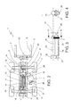
- the reference number 1 globally indicates a telescopic lifting vehicle, according to the present invention.
- the lifting vehicle 1 is constituted by a support frame 2 having a central longitudinal axis of development, at the sides whereof are mounted on one side a control cab 3, on the other an engine 4 for powering the vehicle 1.
- a telescopic arm 5 having its base portion 6 pivotally engaged to a rear portion of the frame 2 itself, according to a horizontal axis perpendicular to the longitudinal axis.
- the arm 5 further has an operative extremity 7 able to be associated to an operative organ 8, such as a lifting fork as shown in the accompanying figures.
- the vehicle 1 is further provided with a front axle 9 and with a rear axle 10 provided with wheels.
- a front axle 9 and with a rear axle 10 provided with wheels.
- the engine 4 which in the preferred embodiment has its own axis positioned horizontally and inclined towards the front part of the longitudinal axis of the vehicle 1, and each of the two axles 9, 10, are further connected, in this order, a transmission 11, a transfer case 12 and a drive shaft 13 developing horizontally under the frame 2.
- the drive shaft 13 is formed by two portions 13a (front portion) and 13b (rear portion) both connected to the transfer case 12.
- the frame 2 between the engine 4 and the cab 3, has a housing 14 open superiorly and developing over the entire length of the vehicle 1 along the longitudinal central axis, inside which can be inserted, at least partially, the telescopic arm 5, when it is in non operative position.
- the arm 5 is movable between the non operative position and an operative position in which it is inclined upwards ( Figures 16 and 18) through a lifting cylinder 15 which has a first end 16 pivotally engaged to the frame 2 and a second end 17 pivotally engaged to the telescopic arm 5, and which is positioned below the telescopic arm 5 itself.
- the frame 2 has a vertical opening 18 in correspondence with at least a part of the housing 14, opening 18 in which the lifting cylinder 15 is inserted when the telescopic arm 5 is recessed in the housing 14. In this circumstance the lifting cylinder 15 projects inferiorly from the frame 2.
- the lifting cylinder 15 is preferably positioned in front of the rear axle 10, behind the transfer case 12, above the drive shaft 13 and below the frame 2.
- the frame 2 is constituted by two lateral bodies 19, 20, each defining a lateral wall of the housing 14, and identifiable as a first body 19 positioned on the side of the cab 3 and a second body 20 positioned on the side of the engine 4, connected to a plurality of brackets 21 having horizontal development, transverse to the longitudinal axis of the vehicle 1, and positioned below the housing 14.
- Each axle 9, 10 is supported by a pair of brackets 21, positioned one in front and one behind it.
- first end 16 of the lifting cylinder 15 is pivotally engaged to one of the brackets 21 supporting the rear axle 10, specifically to the front one 23 of the two.
- the telescopic lifting vehicle I further comprises means 24 for levelling the operative organ 8 to maintain the operative organ 8 parallel to itself during the motions of the arm 5, means which are constituted by a levelling cylinder 25 fastened to the operative end 7 of the arm 5, and by a compensating cylinder 26 hydraulically connected to the levelling cylinder 25.
- the compensation cylinder 26 has a primary end 27 pivotally engaged to the frame 2 and a secondary end 28 pivotally engaged to the telescopic arm 5, and it is positioned parallel and horizontally coplanar to the lifting cylinder 15 below the telescopic arm 5, in such a way as to be also inserted in the opening 17 when the arm 5 is inserted in the housing 14.
- the compensating cylinder 26 has a length equal to that of the lifting cylinder 15, so that the first end 16 of the lifting cylinder 15 and the primary end 27 of the compensating cylinder 26 are pivotally engaged to the frame 2 by means of a single first pivot pin 29, and, similarly, in such a way that the second end 17 of the lifting cylinder 15 and the secondary end 28 of the compensating cylinder are pivotally engaged to the frame 2 by means of a single second pivot pin 30.
- Each pivot pin 29, 30 is inserted through two forks set side by side, fastened to the frame 2, having a central tine in common, and destined one to the lifting cylinder 15 and one to the compensating cylinder 26.
- the telescopic lifting vehicle 1 is also provided with stabilisation means 34 mounted anteriorly to the frame 2, and constituted by a structure 35 bearing two legs 36 each provided with a stabiliser foot 37.
- the structure 35 comprises a portion 38 for latching to the frame 2 and a portion 39 for supporting the legs 36 which extends transversely relative to the vehicle 1.
- the support portion 39 has an arcuate shape going partially around the telescopic arm 5.
- the legs 36 are positioned at the lateral ends of the support portion 39 and have each an inner end 40 pivotally engaged to the support portion 39, and an outer end 41 bearing the stabiliser foot 37.
- Each leg 36 can be actuated between a locked position in which the foot 37 is set down on the ground, and a manoeuvring position in which the foot 37 is raised off the ground.
- the latching portion 38 is associated to a front portion 42 of the frame 2 whilst the supporting portion 39 is integrally connected with the latching portion 38 in its own intermediate portion.
- the supporting portion 39 is below it.
- the latching portion 38 instead is associated to the frame 2 at the two sides of the housing 14, and has, in correspondence with the related areas of coupling to the frame 2, a U shape with a side of the U fastened to the first lateral body 19 and the other side of the U fastened to the second lateral body 20.
- the latching portion 38 also has a second surface 43 able to be associated to the frame 2 below its front portion 42 ( Figure 21).
- each leg 36 The actuation of each leg 36 is performed by a hydraulic actuating cylinder 44 having its jacket and piston associated one below the telescopic arm 5 to the support portion 39 of the structure 35, the other one to the leg 36.
- the hydraulic cylinders are fed by means of a feed valve 45 associated to each cylinder 44 in correspondence with its area close to the leg 36, in such a way as not to be a hindrance for the arm 5 ( Figure 8).
- the operation of the vehicle 1 of the present invention takes place in ways similar to those of traditional telescopic lifters, and directly deducible from the description made heretofore of the vehicle 1 itself.
- the present invention achieves important advantages, since, for the same free height from the ground and the same dimensions of the arm and of the cab, a vehicle in accordance with the present invention has a lower centre of gravity than do vehicles in accordance with the prior art, whilst also assuring an excellent visibility to the operator sitting in the cab.
Landscapes
- Engineering & Computer Science (AREA)
- Transportation (AREA)
- Structural Engineering (AREA)
- Civil Engineering (AREA)
- Life Sciences & Earth Sciences (AREA)
- Geology (AREA)
- Mechanical Engineering (AREA)
- Body Structure For Vehicles (AREA)
- Vehicle Body Suspensions (AREA)
- Vehicle Cleaning, Maintenance, Repair, Refitting, And Outriggers (AREA)
- Fittings On The Vehicle Exterior For Carrying Loads, And Devices For Holding Or Mounting Articles (AREA)
- Forklifts And Lifting Vehicles (AREA)
Priority Applications (7)
| Application Number | Priority Date | Filing Date | Title |
|---|---|---|---|
| AT02425305T ATE320401T1 (de) | 2002-05-15 | 2002-05-15 | Hubfahrzeug mit teleskopischem hebearm |
| DE60209877T DE60209877T2 (de) | 2002-05-15 | 2002-05-15 | Hubfahrzeug mit teleskopischem Hebearm |
| ES02425305T ES2259368T3 (es) | 2002-05-15 | 2002-05-15 | Vehiculo elevador con un brazo de elevacion telescopico. |
| PT02425305T PT1362824E (pt) | 2002-05-15 | 2002-05-15 | Veiculo de levantamento com um braco telescopico de levantamento |
| EP02425305A EP1362824B1 (de) | 2002-05-15 | 2002-05-15 | Hubfahrzeug mit teleskopischem Hebearm |
| US10/158,859 US6699002B2 (en) | 2002-05-15 | 2002-06-03 | Telescopic lifting vehicle |
| CA002398228A CA2398228C (en) | 2002-05-15 | 2002-08-14 | Telescopic lifting vehicle |
Applications Claiming Priority (1)
| Application Number | Priority Date | Filing Date | Title |
|---|---|---|---|
| EP02425305A EP1362824B1 (de) | 2002-05-15 | 2002-05-15 | Hubfahrzeug mit teleskopischem Hebearm |
Publications (2)
| Publication Number | Publication Date |
|---|---|
| EP1362824A1 true EP1362824A1 (de) | 2003-11-19 |
| EP1362824B1 EP1362824B1 (de) | 2006-03-15 |
Family
ID=29266046
Family Applications (1)
| Application Number | Title | Priority Date | Filing Date |
|---|---|---|---|
| EP02425305A Expired - Lifetime EP1362824B1 (de) | 2002-05-15 | 2002-05-15 | Hubfahrzeug mit teleskopischem Hebearm |
Country Status (7)
| Country | Link |
|---|---|
| US (1) | US6699002B2 (de) |
| EP (1) | EP1362824B1 (de) |
| AT (1) | ATE320401T1 (de) |
| CA (1) | CA2398228C (de) |
| DE (1) | DE60209877T2 (de) |
| ES (1) | ES2259368T3 (de) |
| PT (1) | PT1362824E (de) |
Cited By (2)
| Publication number | Priority date | Publication date | Assignee | Title |
|---|---|---|---|---|
| WO2005032996A1 (ja) * | 2003-10-02 | 2005-04-14 | Hitachi Construction Machinery Co., Ltd. | 作業機械 |
| CN102180407A (zh) * | 2011-05-09 | 2011-09-14 | 三一汽车起重机械有限公司 | 一种起重机取力装置及起重机 |
Families Citing this family (6)
| Publication number | Priority date | Publication date | Assignee | Title |
|---|---|---|---|---|
| ITTO20110780A1 (it) * | 2011-08-26 | 2013-02-27 | Merlo Project Srl | Veicolo sollevatore a braccio telescopico e relativo procedimento di fabbricazione |
| USD756057S1 (en) * | 2014-09-04 | 2016-05-10 | Liebherr-Werk Nenzing Gmbh | Reachstacker |
| USD758039S1 (en) * | 2014-09-04 | 2016-05-31 | Liebherr-Werk Nenzing Gmbh | Reachstacker |
| DE102014219104A1 (de) * | 2014-09-23 | 2016-03-24 | Zf Friedrichshafen Ag | Antriebsstrang für ein Fahrzeug |
| CN107337155A (zh) * | 2017-07-13 | 2017-11-10 | 河南麻省新能石化实业有限公司 | 微型自动化叉车及应用方法 |
| CN110468705A (zh) * | 2019-08-29 | 2019-11-19 | 厦门大学嘉庚学院 | 一种可收合的桥梁检测车 |
Citations (4)
| Publication number | Priority date | Publication date | Assignee | Title |
|---|---|---|---|---|
| US5199861A (en) * | 1987-07-27 | 1993-04-06 | Merlo S.P.A. Industria Metalmeccanica | Lifting truck with a telescopic lifting arm |
| EP0692448A1 (de) * | 1994-07-15 | 1996-01-17 | J.C. Bamford Excavators Limited | Handhabungsfahrzeug für Material |
| EP0876932A2 (de) * | 1997-05-09 | 1998-11-11 | Caterpillar Inc. | Kraftübertragungseinrichtung für eine Arbeitsmachine |
| EP1084986A1 (de) * | 1999-09-16 | 2001-03-21 | J.C. Bamford Excavators Limited | Handhabungsfahrzeug für Material |
Family Cites Families (6)
| Publication number | Priority date | Publication date | Assignee | Title |
|---|---|---|---|---|
| DE2739537A1 (de) | 1976-09-03 | 1978-03-09 | Loed Corp | Schwenkgabelanordnung fuer verladeausruestungen |
| US4266909A (en) * | 1979-01-29 | 1981-05-12 | Westendorf Manufacturing Co. | Means for hydraulic self-leveling of a loader bucket |
| US4515520A (en) * | 1982-09-13 | 1985-05-07 | J. I. Case Company | Stabilizer assembly |
| GB2292930B (en) * | 1992-06-30 | 1996-10-02 | Caterpillar Inc | Material handling machine |
| GB9717892D0 (en) * | 1997-08-23 | 1997-10-29 | Jcb Special Products Ltd | Skid steer loader vehicle |
| IT1304978B1 (it) * | 1998-09-10 | 2001-04-05 | Merlo Ind Metalmecc | Veicolo utilizzabile come sollevatore e trattore agricolo. |
-
2002
- 2002-05-15 EP EP02425305A patent/EP1362824B1/de not_active Expired - Lifetime
- 2002-05-15 ES ES02425305T patent/ES2259368T3/es not_active Expired - Lifetime
- 2002-05-15 AT AT02425305T patent/ATE320401T1/de not_active IP Right Cessation
- 2002-05-15 DE DE60209877T patent/DE60209877T2/de not_active Expired - Fee Related
- 2002-05-15 PT PT02425305T patent/PT1362824E/pt unknown
- 2002-06-03 US US10/158,859 patent/US6699002B2/en not_active Expired - Fee Related
- 2002-08-14 CA CA002398228A patent/CA2398228C/en not_active Expired - Fee Related
Patent Citations (4)
| Publication number | Priority date | Publication date | Assignee | Title |
|---|---|---|---|---|
| US5199861A (en) * | 1987-07-27 | 1993-04-06 | Merlo S.P.A. Industria Metalmeccanica | Lifting truck with a telescopic lifting arm |
| EP0692448A1 (de) * | 1994-07-15 | 1996-01-17 | J.C. Bamford Excavators Limited | Handhabungsfahrzeug für Material |
| EP0876932A2 (de) * | 1997-05-09 | 1998-11-11 | Caterpillar Inc. | Kraftübertragungseinrichtung für eine Arbeitsmachine |
| EP1084986A1 (de) * | 1999-09-16 | 2001-03-21 | J.C. Bamford Excavators Limited | Handhabungsfahrzeug für Material |
Cited By (3)
| Publication number | Priority date | Publication date | Assignee | Title |
|---|---|---|---|---|
| WO2005032996A1 (ja) * | 2003-10-02 | 2005-04-14 | Hitachi Construction Machinery Co., Ltd. | 作業機械 |
| CN102180407A (zh) * | 2011-05-09 | 2011-09-14 | 三一汽车起重机械有限公司 | 一种起重机取力装置及起重机 |
| CN102180407B (zh) * | 2011-05-09 | 2012-08-08 | 三一汽车起重机械有限公司 | 一种起重机取力装置及起重机 |
Also Published As
| Publication number | Publication date |
|---|---|
| ATE320401T1 (de) | 2006-04-15 |
| PT1362824E (pt) | 2006-06-30 |
| EP1362824B1 (de) | 2006-03-15 |
| CA2398228A1 (en) | 2003-11-15 |
| ES2259368T3 (es) | 2006-10-01 |
| DE60209877D1 (de) | 2006-05-11 |
| US6699002B2 (en) | 2004-03-02 |
| CA2398228C (en) | 2009-05-19 |
| DE60209877T2 (de) | 2006-11-02 |
| US20030215321A1 (en) | 2003-11-20 |
Similar Documents
| Publication | Publication Date | Title |
|---|---|---|
| US6024191A (en) | Lift apparatus having an articulated double parallelogram boom assembly | |
| CA2307610C (en) | A lifting device with a liftable and tiltable platform | |
| CA2398228C (en) | Telescopic lifting vehicle | |
| US8684198B2 (en) | Working machine | |
| US20010022226A1 (en) | Three-point hitch for a tractor | |
| WO1989000972A1 (en) | A lifting truck with a telescopic lifting arm | |
| EP0003654B1 (de) | Last-Hebevorrichtung | |
| US4024973A (en) | Forklift truck with selectively connectable mast | |
| US4436169A (en) | Elevating and tilting mechanism for crane cab | |
| US5074622A (en) | Scissor frame lift apparatus for dump trucks | |
| CA2582491A1 (en) | Mast assembly in forklift truck | |
| IE20020724A1 (en) | Improvements in and relating to fork lift trucks | |
| NO160430B (no) | Loeftemast. | |
| JP2009057161A (ja) | マスト支持装置 | |
| US6439827B1 (en) | Load handling vehicle | |
| US5421554A (en) | Jack assembly | |
| EP2295366A1 (de) | Hubmast für Gabelstapler | |
| JP2012091901A (ja) | トラクタにおけるアタッチメント式フォークリフト | |
| EP1369376A1 (de) | Teleskopierbarer Fahrzeugmast mit Eigengewichtausgleichszylinder | |
| RU2768979C1 (ru) | Навесной вилочный погрузчик | |
| CN223659769U (zh) | 一种货叉顶升机构与叉车 | |
| GB2364992A (en) | Lifting structure for an industrial truck | |
| GB2254309A (en) | Load lifting apparatus for vehicles | |
| NO813127L (no) | Loeftemast | |
| EP1396467B9 (de) | Verbesserungen an und betreffend Gabelstablern |
Legal Events
| Date | Code | Title | Description |
|---|---|---|---|
| PUAI | Public reference made under article 153(3) epc to a published international application that has entered the european phase |
Free format text: ORIGINAL CODE: 0009012 |
|
| 17P | Request for examination filed |
Effective date: 20021104 |
|
| AK | Designated contracting states |
Kind code of ref document: A1 Designated state(s): AT BE CH CY DE DK ES FI FR GB GR IE IT LI LU MC NL PT SE TR |
|
| AX | Request for extension of the european patent |
Extension state: AL LT LV MK RO SI |
|
| AKX | Designation fees paid |
Designated state(s): AT BE CH CY DE DK ES FI FR GB GR IE IT LI LU MC NL PT SE TR |
|
| 17Q | First examination report despatched |
Effective date: 20040921 |
|
| GRAP | Despatch of communication of intention to grant a patent |
Free format text: ORIGINAL CODE: EPIDOSNIGR1 |
|
| GRAC | Information related to communication of intention to grant a patent modified |
Free format text: ORIGINAL CODE: EPIDOSCIGR1 |
|
| GRAS | Grant fee paid |
Free format text: ORIGINAL CODE: EPIDOSNIGR3 |
|
| GRAA | (expected) grant |
Free format text: ORIGINAL CODE: 0009210 |
|
| AK | Designated contracting states |
Kind code of ref document: B1 Designated state(s): AT BE CH CY DE DK ES FI FR GB GR IE IT LI LU MC NL PT SE TR |
|
| PG25 | Lapsed in a contracting state [announced via postgrant information from national office to epo] |
Ref country code: FI Free format text: LAPSE BECAUSE OF FAILURE TO SUBMIT A TRANSLATION OF THE DESCRIPTION OR TO PAY THE FEE WITHIN THE PRESCRIBED TIME-LIMIT Effective date: 20060315 |
|
| REG | Reference to a national code |
Ref country code: GB Ref legal event code: FG4D Ref country code: CH Ref legal event code: EP |
|
| REG | Reference to a national code |
Ref country code: IE Ref legal event code: FG4D |
|
| REF | Corresponds to: |
Ref document number: 60209877 Country of ref document: DE Date of ref document: 20060511 Kind code of ref document: P |
|
| PG25 | Lapsed in a contracting state [announced via postgrant information from national office to epo] |
Ref country code: IE Free format text: LAPSE BECAUSE OF NON-PAYMENT OF DUE FEES Effective date: 20060515 |
|
| PG25 | Lapsed in a contracting state [announced via postgrant information from national office to epo] |
Ref country code: MC Free format text: LAPSE BECAUSE OF NON-PAYMENT OF DUE FEES Effective date: 20060531 |
|
| REG | Reference to a national code |
Ref country code: CH Ref legal event code: NV Representative=s name: BUGNION S.A. |
|
| PG25 | Lapsed in a contracting state [announced via postgrant information from national office to epo] |
Ref country code: SE Free format text: LAPSE BECAUSE OF FAILURE TO SUBMIT A TRANSLATION OF THE DESCRIPTION OR TO PAY THE FEE WITHIN THE PRESCRIBED TIME-LIMIT Effective date: 20060615 Ref country code: DK Free format text: LAPSE BECAUSE OF FAILURE TO SUBMIT A TRANSLATION OF THE DESCRIPTION OR TO PAY THE FEE WITHIN THE PRESCRIBED TIME-LIMIT Effective date: 20060615 |
|
| REG | Reference to a national code |
Ref country code: PT Ref legal event code: SC4A Effective date: 20060426 |
|
| REG | Reference to a national code |
Ref country code: ES Ref legal event code: FG2A Ref document number: 2259368 Country of ref document: ES Kind code of ref document: T3 |
|
| ET | Fr: translation filed | ||
| PLBE | No opposition filed within time limit |
Free format text: ORIGINAL CODE: 0009261 |
|
| STAA | Information on the status of an ep patent application or granted ep patent |
Free format text: STATUS: NO OPPOSITION FILED WITHIN TIME LIMIT |
|
| 26N | No opposition filed |
Effective date: 20061218 |
|
| PG25 | Lapsed in a contracting state [announced via postgrant information from national office to epo] |
Ref country code: GR Free format text: LAPSE BECAUSE OF FAILURE TO SUBMIT A TRANSLATION OF THE DESCRIPTION OR TO PAY THE FEE WITHIN THE PRESCRIBED TIME-LIMIT Effective date: 20060616 |
|
| PG25 | Lapsed in a contracting state [announced via postgrant information from national office to epo] |
Ref country code: TR Free format text: LAPSE BECAUSE OF FAILURE TO SUBMIT A TRANSLATION OF THE DESCRIPTION OR TO PAY THE FEE WITHIN THE PRESCRIBED TIME-LIMIT Effective date: 20060315 |
|
| PG25 | Lapsed in a contracting state [announced via postgrant information from national office to epo] |
Ref country code: CY Free format text: LAPSE BECAUSE OF FAILURE TO SUBMIT A TRANSLATION OF THE DESCRIPTION OR TO PAY THE FEE WITHIN THE PRESCRIBED TIME-LIMIT Effective date: 20060315 |
|
| PGFP | Annual fee paid to national office [announced via postgrant information from national office to epo] |
Ref country code: ES Payment date: 20090605 Year of fee payment: 8 Ref country code: NL Payment date: 20090504 Year of fee payment: 8 |
|
| PGFP | Annual fee paid to national office [announced via postgrant information from national office to epo] |
Ref country code: AT Payment date: 20090514 Year of fee payment: 8 Ref country code: DE Payment date: 20090511 Year of fee payment: 8 Ref country code: FR Payment date: 20090515 Year of fee payment: 8 Ref country code: IT Payment date: 20090530 Year of fee payment: 8 Ref country code: LU Payment date: 20090616 Year of fee payment: 8 Ref country code: PT Payment date: 20090505 Year of fee payment: 8 |
|
| PGFP | Annual fee paid to national office [announced via postgrant information from national office to epo] |
Ref country code: BE Payment date: 20090525 Year of fee payment: 8 |
|
| PGFP | Annual fee paid to national office [announced via postgrant information from national office to epo] |
Ref country code: CH Payment date: 20090513 Year of fee payment: 8 |
|
| PGFP | Annual fee paid to national office [announced via postgrant information from national office to epo] |
Ref country code: GB Payment date: 20090513 Year of fee payment: 8 |
|
| REG | Reference to a national code |
Ref country code: PT Ref legal event code: MM4A Free format text: LAPSE DUE TO NON-PAYMENT OF FEES Effective date: 20101115 |
|
| BERE | Be: lapsed |
Owner name: *KOMATSU UTILITY EUROPE S.P.A. Effective date: 20100531 |
|
| REG | Reference to a national code |
Ref country code: NL Ref legal event code: V1 Effective date: 20101201 |
|
| REG | Reference to a national code |
Ref country code: CH Ref legal event code: PL |
|
| GBPC | Gb: european patent ceased through non-payment of renewal fee |
Effective date: 20100515 |
|
| PG25 | Lapsed in a contracting state [announced via postgrant information from national office to epo] |
Ref country code: AT Free format text: LAPSE BECAUSE OF NON-PAYMENT OF DUE FEES Effective date: 20100515 |
|
| REG | Reference to a national code |
Ref country code: FR Ref legal event code: ST Effective date: 20110131 |
|
| PG25 | Lapsed in a contracting state [announced via postgrant information from national office to epo] |
Ref country code: CH Free format text: LAPSE BECAUSE OF NON-PAYMENT OF DUE FEES Effective date: 20100531 Ref country code: LI Free format text: LAPSE BECAUSE OF NON-PAYMENT OF DUE FEES Effective date: 20100531 Ref country code: PT Free format text: LAPSE BECAUSE OF NON-PAYMENT OF DUE FEES Effective date: 20101115 |
|
| PG25 | Lapsed in a contracting state [announced via postgrant information from national office to epo] |
Ref country code: IT Free format text: LAPSE BECAUSE OF NON-PAYMENT OF DUE FEES Effective date: 20100515 Ref country code: BE Free format text: LAPSE BECAUSE OF NON-PAYMENT OF DUE FEES Effective date: 20100531 Ref country code: NL Free format text: LAPSE BECAUSE OF NON-PAYMENT OF DUE FEES Effective date: 20101201 |
|
| PG25 | Lapsed in a contracting state [announced via postgrant information from national office to epo] |
Ref country code: DE Free format text: LAPSE BECAUSE OF NON-PAYMENT OF DUE FEES Effective date: 20101201 |
|
| PG25 | Lapsed in a contracting state [announced via postgrant information from national office to epo] |
Ref country code: FR Free format text: LAPSE BECAUSE OF NON-PAYMENT OF DUE FEES Effective date: 20100531 |
|
| REG | Reference to a national code |
Ref country code: ES Ref legal event code: FD2A Effective date: 20110714 |
|
| PG25 | Lapsed in a contracting state [announced via postgrant information from national office to epo] |
Ref country code: GB Free format text: LAPSE BECAUSE OF NON-PAYMENT OF DUE FEES Effective date: 20100515 Ref country code: ES Free format text: LAPSE BECAUSE OF NON-PAYMENT OF DUE FEES Effective date: 20110704 |
|
| PG25 | Lapsed in a contracting state [announced via postgrant information from national office to epo] |
Ref country code: ES Free format text: LAPSE BECAUSE OF NON-PAYMENT OF DUE FEES Effective date: 20100516 |
|
| PG25 | Lapsed in a contracting state [announced via postgrant information from national office to epo] |
Ref country code: LU Free format text: LAPSE BECAUSE OF NON-PAYMENT OF DUE FEES Effective date: 20100515 |