EP1361715B1 - Verfahren zum Bestimmen der Signalausbreitungseigenschaften eines drahtlos übertragbaren Signals - Google Patents
Verfahren zum Bestimmen der Signalausbreitungseigenschaften eines drahtlos übertragbaren Signals Download PDFInfo
- Publication number
- EP1361715B1 EP1361715B1 EP02009360A EP02009360A EP1361715B1 EP 1361715 B1 EP1361715 B1 EP 1361715B1 EP 02009360 A EP02009360 A EP 02009360A EP 02009360 A EP02009360 A EP 02009360A EP 1361715 B1 EP1361715 B1 EP 1361715B1
- Authority
- EP
- European Patent Office
- Prior art keywords
- signal
- parameters
- iteration step
- partial
- parameter
- Prior art date
- Legal status (The legal status is an assumption and is not a legal conclusion. Google has not performed a legal analysis and makes no representation as to the accuracy of the status listed.)
- Expired - Lifetime
Links
- 238000000034 method Methods 0.000 title claims description 53
- 235000002020 sage Nutrition 0.000 claims abstract description 6
- 230000008859 change Effects 0.000 claims description 3
- 230000002123 temporal effect Effects 0.000 claims 1
- 238000012986 modification Methods 0.000 abstract description 2
- 230000004048 modification Effects 0.000 abstract description 2
- 238000012217 deletion Methods 0.000 abstract 1
- 230000037430 deletion Effects 0.000 abstract 1
- 230000014759 maintenance of location Effects 0.000 abstract 1
- 238000005457 optimization Methods 0.000 description 31
- 230000005855 radiation Effects 0.000 description 18
- 238000011156 evaluation Methods 0.000 description 11
- 230000006978 adaptation Effects 0.000 description 4
- 238000011161 development Methods 0.000 description 3
- 230000008569 process Effects 0.000 description 3
- 239000013598 vector Substances 0.000 description 3
- 238000004364 calculation method Methods 0.000 description 2
- 238000004891 communication Methods 0.000 description 2
- 238000013461 design Methods 0.000 description 2
- 238000012636 positron electron tomography Methods 0.000 description 2
- 230000001133 acceleration Effects 0.000 description 1
- 230000008901 benefit Effects 0.000 description 1
- 238000007796 conventional method Methods 0.000 description 1
- 230000007547 defect Effects 0.000 description 1
- 238000001514 detection method Methods 0.000 description 1
- 238000001228 spectrum Methods 0.000 description 1
- 230000007480 spreading Effects 0.000 description 1
Classifications
-
- H—ELECTRICITY
- H04—ELECTRIC COMMUNICATION TECHNIQUE
- H04L—TRANSMISSION OF DIGITAL INFORMATION, e.g. TELEGRAPHIC COMMUNICATION
- H04L25/00—Baseband systems
- H04L25/02—Details ; arrangements for supplying electrical power along data transmission lines
- H04L25/0202—Channel estimation
Definitions
- the invention relates to a method for determining the signal propagation properties a wirelessly transmitted signal, in particular mobile radio signal, in which a Signal emitted in at least one radiation area in at least one reception area is received and values of parameters of a given signal model Adaptation of a signal estimated on the basis of the signal model to the received one Signal are optimized in a sequence of iteration steps, and a digital storage medium with which Help the procedure can be carried out.
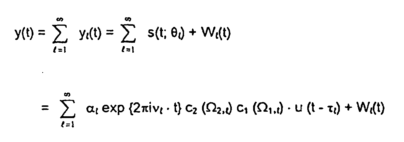
- the signal y (t) received in a reception area is composed of a multiplicity of partial signals y l (t), each of which has a signal component s (t; ⁇ l caused by the emitted signal ) and has a noise component W l (t).
- ⁇ l denotes the complex amplitude of the partial signal l
- ⁇ l the Doppler shift of the partial signal l with respect to the radiated signal caused by reflection on a possibly movable reflector, the emission of the signal by a movable transmitter and / or the reception of the signal by a movable receiver Signal
- ⁇ 2, l the angle of incidence of the partial signal l in the reception area
- ⁇ 1, l the radiation direction of the partial signal l from the radiation area c 2 the reception characteristic of the reception area
- c 1 the radiation characteristic of the radiation area
- ⁇ l the signal propagation time of the partial signal l from the radiation area to the reception area
- ⁇ l the parameter vector [ ⁇ 1, l , ⁇ 2, l , ⁇ l , ⁇ l , ⁇ l , ⁇ l ] of the partial signal l.
- the partial signals y l (t) can be signals emitted by a radiation area and reached the reception area via different signal propagation paths and / or signals emitted by different radiation areas to the reception area.
- the number of partial signals taken into account in the signal evaluation is designated by L.
- the parameter vector ⁇ and ML ( y ) with which the signal estimated on the basis of the signal model can be optimally adapted to the received signal y (t) can be assumed to be the value of ⁇ for which the function ⁇ ( ⁇ ; y) is maximal becomes:
- the "Expectation Maximization Algorithm" already mentioned above for solving the optimization task was specified, in which the parameter sets ⁇ l for the individual partial signals are optimized independently of one another so that the 8L-dimensional optimization problem in L is broken down into eight-dimensional problems.
- the SAGE algorithm which was also mentioned above, was proposed in that the individual eight-dimensional optimization problems for each partial signal are resolved into eight one-dimensional problems.
- the object of the invention based on specifying a further development of the known methods, which a realistic Description of the signal propagation properties with given signal models allowed and to specify and a device for performing such methods to provide appropriate digital storage medium.
- This invention is based on the incredibly simple finding that the im Problems observed in the prior art are primarily caused by that in conventional methods with regard to the available computer capacity both the number of iteration steps and the number of considered Partial signals is determined before the start of iterative optimization. That can break off iterative optimization before reaching a satisfactory system description lead to sufficient convergence.
- the number of iteration steps is not determined in advance, but after each iteration step depending on the result of the iterative optimization, an evaluation is carried out, whether a sufficient system description has been achieved. Provided that this requirement is not satisfied, the iterative optimization is continued.
- a limit for the integral Deviation of the estimated signal from the received signal can be set.
- a limit value for the maximum can also be used as the termination criterion Deviation can be determined. If the relevant limit values are undershot the iterative optimization is then canceled.
- the iterative optimization are examined whether individual parameter sets are predetermined Convergence criteria meet, i.e. whether the parameter values of the individual parameter sets in the evaluated iteration step a predetermined limit for a deviation from the corresponding parameter value determined in a previous iteration step below.
- the evaluation step carried out in the method according to the invention requires additional evaluation capacity. Furthermore, the variable design of the number of Iteration steps without further modification of the known methods lead to a disproportionately long evaluation time is required. In extreme cases, without further Changes to the known methods do not meet the specified convergence criteria, so that the process of iterative optimization is not completed.
- adjustments can include taking into account new partial signals. The may be necessary if the initially specified number of partial signals is used realistic description of the signal propagation environment is not sufficient. alternative or additionally during the execution of the method according to the invention iterative optimization, individual parameters are also ignored, i.e. at one or No further optimization was carried out after several successive iteration steps become. Corresponding partial signals can either be completely from that of the iterative Optimization underlying signal model removed or in this signal model can be assumed to be constant.
- the complete removal of the corresponding Partial signal from the signal model can be used in the context of the method according to the invention then take place when the amplitude of the corresponding partial signal falls below a predetermined limit value, possibly via a predetermined number of successive iteration steps.
- a temporary one Ignoring individual parameters or parameter sets can be done within the scope of the invention Procedure take place when the corresponding parameters at a given Number of successive iteration steps none a predetermined limit have undergone a transitional change. This limit can be like the others limit values mentioned above can be made variable, so that in one Iteration step ignored parameters in a later iteration step become.
- the parameter values usually in each iteration step to adapt the estimated signal to the measuring signal varies step by step. This can further accelerate the process can be achieved if at least one parameter value in at least one iteration step only in a specified sub-range of a possible value range for this Parameter is varied.
- Such a measure can be useful, for example, if the physical environment for signal propagation is the propagation path for a or makes several partial signals appear particularly probable and for these partial signals individual parameter values depending on the environment are particularly reliable can be predicted.
- the sub-ranges of corresponding parameter values other sub-signals are determined by making the sub-range particularly reliable predictable partial signal is excluded from the possible value range. In this way, even partial signals outside of the most likely signal propagation paths can be reliably determined.
- a further acceleration in the execution of methods according to the invention can be achieved if for at least one parameter value of the signal model Step size for the variation within at least one iteration step and / or between successive iteration steps is varied.
- the embodiment according to the invention The method expediently assumed that the measured signal after predetermined signal model from a plurality of each by a corresponding one Parameter set defined partial signals is formed and the optimization of the adaptation of the individual parameter values can be executed in a sequence of partial iteration steps, in each of which an optimization of the values for a parameter set assuming constant values for the parameters of the other parameter sets.
- the Results of the partial iteration steps within a sequence of partial iteration steps having the complete iteration step are already taken into account if in a Sub-iteration step determined parameter values of a parameter set for a subsequent one Partial iteration step of the same iteration step as constant values for this parameter set be accepted. This can significantly speed up the process can be achieved.
- the parameter values of in the corresponding iteration step parameter sets not yet dealt with in at least one partial iteration step are at least partially adopted from the previous iteration step.
- Partial signals already taken into account in the method at least with regard to a plurality hide a parameter of similar partial signals. This can generally. be recognized by that a parameter value of a parameter set is between two successive ones Iteration steps changed particularly strongly.
- Embodiment of the invention characterized in that in the step of evaluating in the corresponding iteration step optimized values of the parameters of at least one Parameter set with the values optimized for in a previous iteration step the parameters of the same parameter set are compared and one above predetermined limit value change of at least one parameter value in in a subsequent iteration step, a new parameter set of the signal model is taken into account becomes.
- the method according to the invention can be used with particular advantage using the SAGE algorithm for parameter optimization, in which, in at least one partial iteration step, the optimization of the adaptation of the parameter values of a parameter set is carried out in a sequence of subiteration steps, in each of which an optimization of the adaptation of a subset of the Parameter values of the same parameter set are made assuming constant values for the other parameters of this parameter set.
- the signal model specified above is generally assumed, in which it is assumed that the measured signal y (t) is present as a superposition of a number of partial signals y l (t).
- the determination of the initial values for the iterative optimization carried out in the course of the method according to the invention can be further improved if the initial values for the parameters of a parameter set are successively determined using the received signal and the previously determined initial values of the parameters of this parameter set.
- initial values for parameter sets that belong to partial signals that are only taken into account after execution of at least one iteration step can be determined using previously determined parameter values of the other partial signals.
- the partial signal y l (t) is preferably first determined on the basis of the measured signal and the already determined initial values of the parameter sets.
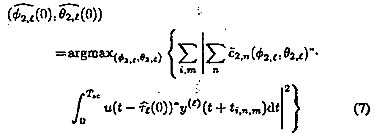
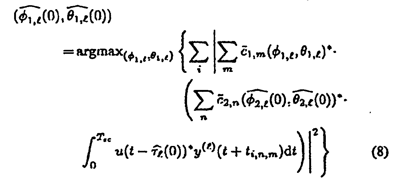
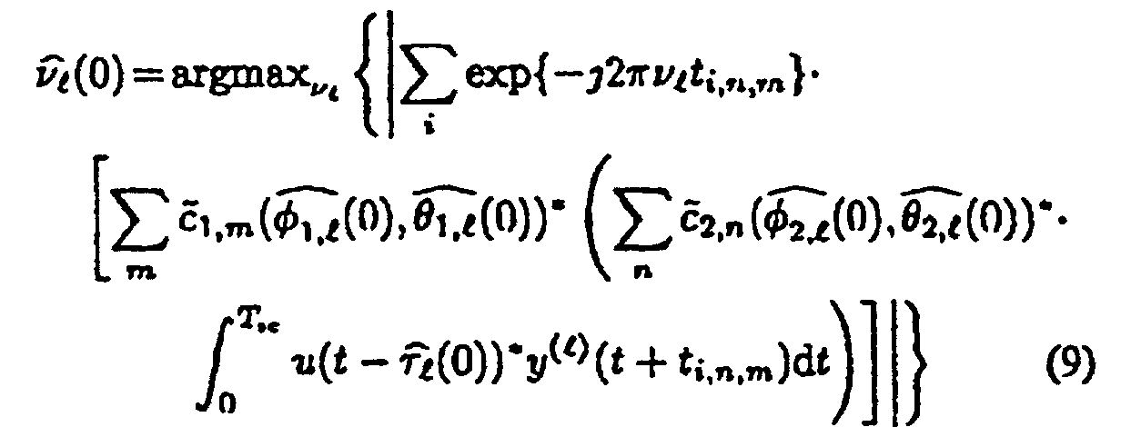
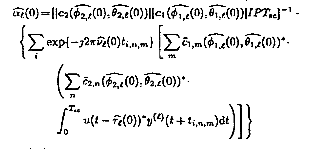
- the coordinate pairs ( ⁇ 1, l , ⁇ 1, l ) and ( ⁇ 2, l , ⁇ 2, l ) denote the direction of incidence or the radiation direction of the corresponding partial signal, polar coordinates, t i, n, m the start time of one in one Measuring cycle i from a radiation element n emitted and received by a receiving element m code signal, T sc the duration for which the subchannel with the radiation element n and the receiving element m is switched for evaluation and standardized steering vectors for the radiation area and the reception area.
- the evaluation device for Execution of the variable iterative optimization method explained above is operable is.
Landscapes
- Engineering & Computer Science (AREA)
- Power Engineering (AREA)
- Computer Networks & Wireless Communication (AREA)
- Signal Processing (AREA)
- Radio Transmission System (AREA)
- Inspection Of Paper Currency And Valuable Securities (AREA)
- Analysing Materials By The Use Of Radiation (AREA)
- Radar Systems Or Details Thereof (AREA)
- Monitoring And Testing Of Transmission In General (AREA)
Description


Für ℓ = 1,...,L


Claims (18)
- Verfahren zum Bestimmen der Signalausbreitungseigenschaften eines drahtlos übertragenen Signals, insbesondere Mobilfunksignals, bei dem ein mindestens in einem Abstrahlbereich abgestrahltes Signal in mindestens einem Empfangsbereich empfangen wird und Werte von Parametern eines vorgegebenen Signalmodells zur Anpassung eines auf Grundlage des Signalmodells geschätzten Signals an das empfangene Signal in einer Folge von Iterationsschritten optimiert werden, dadurch gekennzeichnet, daß das Ergebnis der iterativen Optimierung nach jedem Iterationsschritt bewertet und in Abhängigkeit von dem Ergebnis der Bewertung festgelegt wird, oba) die iterative Optimierung abgebrochen oderb1) für den nächsten Iterationsschritt mindestens ein neuer Parameter des Signalmodells berücksichtigt und/oderb2) mindestens ein Parameter des Signalmodells beim nächsten Iterationsschritt ignoriert wird oderb3) der nächste Iterationsschritt ohne Änderung der berücksichtigten Parameter durchgeführt wird.
- Verfahren nach Anspruch 1, dadurch gekennzeichnet, daß mindestens ein in einem Iterationsschritt ignorierter Parameter in einem späten Iterationsschritt wieder berücksichtigt wird.
- Verfahren nach Anspruch 1 oder 2, dadurch gekennzeichnet, daß die Werte der Parameter in jedem Iterationsschritt zur Anpassung des geschätzten Signals an das gemessene Signal schrittweise variiert werden.
- Verfahren nach Anspruch 3, dadurch gekennzeichnet, daß mindestens ein Parameterwert in mindestens einem Iterationsschritt nur in einem vorgegebenen Teilbereich eines möglichen Wertebereichs für diesen Parameter variiert wird.
- Verfahren nach Anspruch 3 oder 4, dadurch gekennzeichnet, daß für mindestens einen Parameterwert des Signalmodells die Schrittweite bei der Variation innerhalb mindestens eines Iterationsschrittes und/oder zwischen aufeinanderfolgenden Iterationsschritten variiert wird.
- Verfahren nach einem der vorhergehenden Ansprüche, dadurch gekennzeichnet, daß das gemessene Signal nach dem vorgegebenen Signalmodell aus einer Mehrzahl von jeweils durch einen entsprechenden Parametersatz definierten Teilsignalen gebildet ist und die Optimierung der Anpassung in einer Folge von Teiliterationsschritten ausgeführt wird, in denen jeweils eine Optimierung der Anpassung der Werte für einen Parametersatz unter der Annahme konstanter Werte für die Parameter der übrigen Parametersätze erfolgt.
- Verfahren nach Anspruch 6, dadurch gekennzeichnet, daß in einem Teiliterationsschritt ermittelte Parameterwerte eines Parametersatzes bei einem folgenden Teiliterationsschritt desselben Iterationsschrittes als konstante Werte für diesen Parametersatz angenommen werden und/oder mindestens ein in einem vorhergehenden Iterationsschritt ermittelter Parameterwert bei mindestens einem Teiliterationsschritt als konstanter Wert angenommen wird.
- Verfahren nach Anspruch 7, dadurch gekennzeichnet, daß die Reihenfolge der Ausführung der Teiliterationsschritte eines Iterationsschrittes in Abhängigkeit von den in einem vorhergehenden Iterationsschritt optimierten Parameterwerten der Parametersätze bestimmt wird.
- Verfahren nach Anspruch 8, dadurch gekennzeichnet, daß die Teiliterationsschritte in einem Iterationsschritt in einer der in einem vorhergehenden Iterationsschritt optimierten Amplituden der Teilsignale entsprechenden Reihenfolge beginnend mit dem die höchste/kleinste Amplitude aufweisenden Teilsignal ausgeführt werden.
- Verfahren nach den Ansprüchen 6 bis 9, dadurch gekennzeichnet, daß bei der Bewertung in einem Iterationsschritt optimierte Werte der Parameter mindestens eines Parametersatzes mit den in einem vorhergehenden Iterationsschritt optimierten Werten für die Parameter desselben Satzes verglichen werden und bei einer oberhalb eines vorgegebenen Grenzwertes liegenden Änderung eines Parameterwertes in einem folgenden Iterationsschritt ein neuer Parametersatz des Signalmodells berücksichtigt wird.
- Verfahren nach den Ansprüchen 6 bis 10, dadurch gekennzeichnet, daß in mindestens einem Teiliterationsschritt die Optimierung der Anpassung in einer Folge von Unteriterationsschritten ausgeführt wird, in denen jeweils eine Optimierung der Anpassung einer Teilmenge der Parameterwerte desselben Parametersatzes unter Annahme konstanter Werte für die übrigen Parameter dieses Parametersatzes erfolgt, insbesondere nach dem SAGE-Algorithmus.
- Verfahren nach Anspruch 11, dadurch gekennzeichnet, daß jeder Parameter eines Parametersatzes einer physikalisch meßbaren Größe des entsprechenden Teilsignals, wie etwa einer Verzögerungszeit, einer Dopplerfrequenz oder einer Einfallsrichtung zugeordnet ist, und die Unteriterationsschritte in der Reihenfolge der natürlichen Auflösungen der entsprechenden physikalischen Größe, beginnend mit dem der physikalischen Größe höchster natürlicher Auflösung entsprechenden Parameter ausgeführt werden.
- Verfahren nach einem der vorhergehenden Ansprüche, dadurch gekennzeichnet, daß das gemessene Signal y (t) nach dem folgenden Signalmodell ggf. unter zusätzlicher Berücksichtigung weiterer Signaleigenschaften beschrieben wird:wobei gilt:
- αℓ =
- komplexe Amplitude des Teilsignals ℓ
- νℓ =
- Dopplerverschiebung des Teilsignals ℓ
- Ω2,ℓ =
- Einfallsrichtung des Teilsignals ℓ in den Empfangsbereich
- Ω1,ℓ =
- Abstrahlrichtung des Teilsignals ℓ vom Abstrahlbereich
- τℓ =
- Signallaufzeit des Teilsignals ℓ vom Abstrahlbereich zum Empfangsbereich
- c2 =
- Empfangscharakteristik des Empfangsbereichs
- c1 =
- Abstrahlcharakteristik des Abstrahlbereichs
- ℓ =
- [Ω1,ℓ, Ω2,ℓ, τℓ, νℓ, αℓ]
- Wℓ =
- räumlich und zeitlich weißes Rauschen
- u =
- abgestrahltes Testsignal
- Verfahren zum Bestimmen der Signalausbreitungseigenschaften eines drahtlos übertragbaren Signals, nach einem der vorhergehenden Ansprüche, bei dem ein in einem Abstrahlbereich abgestrahltes Signal in einem Empfangsbereich empfangen wird und
Parameter eines vorgegebenen Signalmodells zur Anpassung eines auf Grundlage des Signalmodells geschätzten Signals an das empfangene Signal iterativ optimiert werden,
dadurch gekennzeichnet, daß der Anfangswert der iterativen Optimierung für mindestens einen Parameter des Signalmodells unter Verwendung des empfangenen Signals bestimmt wird. - Verfahren nach Anspruch 14, dadurch gekennzeichnet, daß die Anfangswerte für die einzelnen Parametersätze des Signalmodells nacheinander bestimmt werden, wobei bei der Bestimmung der Anfangswerte für mindestens einen Parametersatz das empfangene Signal und bereits zuvor bestimmte Anfangswerte mindestens eines anderen Parametersatzes berücksichtigt werden.
- Verfahren nach Anspruch 14 oder 15, bei dem die Anfangswerte für die Parameter eines Parametersatzes nacheinander unter Verwendung des empfangenen Signals und der zuvor bereits bestimmten Anfangswerte der Parameter dieses Parametersatzes bestimmt werden.
- Verfahren nach den Ansprüchen 14 bis 15, dadurch gekennzeichnet, daß die Anfangswerte (τ andℓ(0); Ω and2,ℓ(0); Ω1,ℓ(0); νℓ(0); αℓ(0)) für die Parametersätze (τℓ,Ω2,ℓ, Ω1,ℓ, νℓ, αℓ ) der einzelnen Teilsignale yℓ(t) wie folgt bestimmt werden:
Für ℓ = 1,...,L

- Digitales Speichermedium, insbesondere Diskette oder CD-ROM, mit elektronisch auslesbaren Steuersignalen, die so mit einem programmierbaren Computersystem einer Abstrahleinrichtung und einer Empfangseinrichtung zusammenwirken können, daß ein Verfahren nach einem der Ansprüche 1 bis 17 ausgeführt wird.
Priority Applications (4)
| Application Number | Priority Date | Filing Date | Title |
|---|---|---|---|
| AT02009360T ATE264582T1 (de) | 2002-05-03 | 2002-05-03 | Verfahren zum bestimmen der signalausbreitungseigenschaften eines drahtlos übertragbaren signals |
| DE50200358T DE50200358D1 (de) | 2002-05-03 | 2002-05-03 | Verfahren zum Bestimmen der Signalausbreitungseigenschaften eines drahtlos übertragbaren Signals |
| EP02009360A EP1361715B1 (de) | 2002-05-03 | 2002-05-03 | Verfahren zum Bestimmen der Signalausbreitungseigenschaften eines drahtlos übertragbaren Signals |
| DK02009360T DK1361715T3 (da) | 2002-05-03 | 2002-05-03 | Fremgangsmåde til bestemmelse af signaludbredelsesegenskaberne for et trådlöst transmitterbart signal |
Applications Claiming Priority (1)
| Application Number | Priority Date | Filing Date | Title |
|---|---|---|---|
| EP02009360A EP1361715B1 (de) | 2002-05-03 | 2002-05-03 | Verfahren zum Bestimmen der Signalausbreitungseigenschaften eines drahtlos übertragbaren Signals |
Publications (2)
| Publication Number | Publication Date |
|---|---|
| EP1361715A1 EP1361715A1 (de) | 2003-11-12 |
| EP1361715B1 true EP1361715B1 (de) | 2004-04-14 |
Family
ID=29225599
Family Applications (1)
| Application Number | Title | Priority Date | Filing Date |
|---|---|---|---|
| EP02009360A Expired - Lifetime EP1361715B1 (de) | 2002-05-03 | 2002-05-03 | Verfahren zum Bestimmen der Signalausbreitungseigenschaften eines drahtlos übertragbaren Signals |
Country Status (4)
| Country | Link |
|---|---|
| EP (1) | EP1361715B1 (de) |
| AT (1) | ATE264582T1 (de) |
| DE (1) | DE50200358D1 (de) |
| DK (1) | DK1361715T3 (de) |
Families Citing this family (2)
| Publication number | Priority date | Publication date | Assignee | Title |
|---|---|---|---|---|
| EP3900284B1 (de) * | 2018-12-17 | 2023-11-08 | U-blox AG | Schätzung von einem oder mehreren merkmalen eines kommunikationskanals |
| CN112671489B (zh) * | 2020-12-17 | 2022-07-12 | 重庆邮电大学 | 基于沃特森模型的短波航空移动信道建模方法 |
Family Cites Families (1)
| Publication number | Priority date | Publication date | Assignee | Title |
|---|---|---|---|---|
| FR2794589B1 (fr) * | 1999-06-02 | 2001-08-24 | France Telecom | Procede de communications radiomobiles amrt iteratif |
-
2002
- 2002-05-03 DE DE50200358T patent/DE50200358D1/de not_active Expired - Lifetime
- 2002-05-03 AT AT02009360T patent/ATE264582T1/de active
- 2002-05-03 EP EP02009360A patent/EP1361715B1/de not_active Expired - Lifetime
- 2002-05-03 DK DK02009360T patent/DK1361715T3/da active
Also Published As
| Publication number | Publication date |
|---|---|
| ATE264582T1 (de) | 2004-04-15 |
| DE50200358D1 (de) | 2004-05-19 |
| EP1361715A1 (de) | 2003-11-12 |
| DK1361715T3 (da) | 2004-05-10 |
Similar Documents
| Publication | Publication Date | Title |
|---|---|---|
| DE69937268T2 (de) | Funkkommunikationssystem mit einer Raum-Zeit-Architektur unter Verwendung von Multielementantennen sowohl beim Sender als auch beim Empfänger | |
| EP1327314B1 (de) | Strahlformungsverfahren | |
| DE3808172C2 (de) | ||
| DE20311842U1 (de) | Gerät zur Lokalisierung mobiler Endgeräte auf Grundlage von Winkelmessungen | |
| DE60303693T2 (de) | Radarsystem | |
| DE102013106402A1 (de) | Zielobjekt-Erfassungsvorrichtung und Echosignal-Verarbeitungsverfahren | |
| DE112010003247T5 (de) | Reifeninformation-Überwachungsvorrichtung | |
| DE112015006184T5 (de) | Empfangsvorrichtung und Empfangsverfahren | |
| DE69634466T2 (de) | Mehrbenutzerempfang für CDMA | |
| DE60125723T2 (de) | Schätzung des antenneneinfallswinkels unter verwendung des gewichtsvektors für die aufwärtsverbindung | |
| DE19962949A1 (de) | Vorrichtung zur abtaststrahlungsbasierten Oberflächenzustandserkennung insbesondere von Straßen | |
| WO1998043459A2 (de) | Verfahren zum kanalschätzen aus über einen funkkanal übertragenen empfangssignalen | |
| EP2351267B1 (de) | Vorrichtung und verfahren zur frequenzselektiven belegungserfassung | |
| DE102010011415B3 (de) | Verfahren zur Ermittlung und zum Tracking von Eigenschaften eines Funkübertragungskanals | |
| EP0970388A2 (de) | Verfahren zum richtungsschätzen | |
| DE69912448T2 (de) | Iterativer rake-empfänger und entsprechendes empfangsverfahren | |
| DE102013111633B4 (de) | Verfahren und Vorrichtung für Funkortung | |
| EP1361715A1 (de) | Verfahren zum Bestimmen der Signalausbreitungseigenschaften eines drahtlos übertragbaren Signals | |
| DE69903957T2 (de) | Funkverfahren zur bestimmung der geschwindigkeit einer mobilstation | |
| DE69520508T2 (de) | Verfahren zur verbesserung von durch radar erfassten daten | |
| DE60035099T2 (de) | Verfahren zur bestimmung der rahmenfrequenz eines datenrahmens in einem kommunikationssystem | |
| DE102004041121B3 (de) | Verfahren zum Untersuchen eines Funkkanals | |
| DE102012209113A1 (de) | Verfahren zur rechnergestützten Verarbeitung von SAR-Rohdaten | |
| DE102012219225B4 (de) | Synthetik-Apertur-Radarverfahren und Synthetik-Apertur-Radarvorrichtung | |
| EP3249426A1 (de) | Synthetik-apertur-radarverfahren |
Legal Events
| Date | Code | Title | Description |
|---|---|---|---|
| GRAP | Despatch of communication of intention to grant a patent |
Free format text: ORIGINAL CODE: EPIDOSNIGR1 |
|
| PUAI | Public reference made under article 153(3) epc to a published international application that has entered the european phase |
Free format text: ORIGINAL CODE: 0009012 |
|
| GRAS | Grant fee paid |
Free format text: ORIGINAL CODE: EPIDOSNIGR3 |
|
| 17P | Request for examination filed |
Effective date: 20030310 |
|
| AK | Designated contracting states |
Kind code of ref document: A1 Designated state(s): AT BE CH CY DE DK ES FI FR GB GR IE IT LI LU MC NL PT SE TR |
|
| AX | Request for extension of the european patent |
Extension state: AL LT LV MK RO SI |
|
| GRAA | (expected) grant |
Free format text: ORIGINAL CODE: 0009210 |
|
| AK | Designated contracting states |
Kind code of ref document: B1 Designated state(s): AT CH DE DK FR GB LI SE |
|
| REG | Reference to a national code |
Ref country code: GB Ref legal event code: FG4D Free format text: NOT ENGLISH |
|
| REG | Reference to a national code |
Ref country code: CH Ref legal event code: EP |
|
| REG | Reference to a national code |
Ref country code: DK Ref legal event code: T3 |
|
| REG | Reference to a national code |
Ref country code: CH Ref legal event code: NV Representative=s name: WERNER FENNER PATENTANWALT |
|
| REF | Corresponds to: |
Ref document number: 50200358 Country of ref document: DE Date of ref document: 20040519 Kind code of ref document: P |
|
| REG | Reference to a national code |
Ref country code: IE Ref legal event code: FG4D Free format text: GERMAN |
|
| REG | Reference to a national code |
Ref country code: SE Ref legal event code: TRGR |
|
| AKX | Designation fees paid |
Designated state(s): AT CH DE DK FR GB LI SE |
|
| GBT | Gb: translation of ep patent filed (gb section 77(6)(a)/1977) |
Effective date: 20040719 |
|
| LTIE | Lt: invalidation of european patent or patent extension |
Effective date: 20040414 |
|
| ET | Fr: translation filed | ||
| REG | Reference to a national code |
Ref country code: IE Ref legal event code: FD4D |
|
| PLBE | No opposition filed within time limit |
Free format text: ORIGINAL CODE: 0009261 |
|
| STAA | Information on the status of an ep patent application or granted ep patent |
Free format text: STATUS: NO OPPOSITION FILED WITHIN TIME LIMIT |
|
| 26N | No opposition filed |
Effective date: 20050117 |
|
| REG | Reference to a national code |
Ref country code: GB Ref legal event code: 732E |
|
| REG | Reference to a national code |
Ref country code: CH Ref legal event code: PUE Owner name: ELEKTROBIT TESTING LTD. Free format text: ELEKTROBIT AG#ROSSWIESSTRASSE 29#8608 BUBIKON (CH) -TRANSFER TO- ELEKTROBIT TESTING LTD.#AUTOMAATIOTIE 1#90460 OULUNSALO (FI) |
|
| REG | Reference to a national code |
Ref country code: FR Ref legal event code: TP |
|
| REG | Reference to a national code |
Ref country code: CH Ref legal event code: PUE Owner name: JOT AUTOMATION OY Free format text: ELEKTROBIT TESTING LTD.#AUTOMAATIOTIE 1#90460 OULUNSALO (FI) -TRANSFER TO- JOT AUTOMATION OY#PAULAHARJUNTIE 20#90530 OULU (FI) |
|
| REG | Reference to a national code |
Ref country code: CH Ref legal event code: NV Representative=s name: WERNER FENNER PATENTANWALT |
|
| REG | Reference to a national code |
Ref country code: GB Ref legal event code: 732E |
|
| REG | Reference to a national code |
Ref country code: FR Ref legal event code: CD Ref country code: FR Ref legal event code: TP |
|
| PGFP | Annual fee paid to national office [announced via postgrant information from national office to epo] |
Ref country code: AT Payment date: 20120511 Year of fee payment: 11 |
|
| PGFP | Annual fee paid to national office [announced via postgrant information from national office to epo] |
Ref country code: DK Payment date: 20130521 Year of fee payment: 12 Ref country code: SE Payment date: 20130521 Year of fee payment: 12 Ref country code: CH Payment date: 20130523 Year of fee payment: 12 |
|
| PGFP | Annual fee paid to national office [announced via postgrant information from national office to epo] |
Ref country code: FR Payment date: 20130603 Year of fee payment: 12 |
|
| REG | Reference to a national code |
Ref country code: CH Ref legal event code: PL |
|
| REG | Reference to a national code |
Ref country code: DK Ref legal event code: EBP Effective date: 20140531 |
|
| REG | Reference to a national code |
Ref country code: AT Ref legal event code: MM01 Ref document number: 264582 Country of ref document: AT Kind code of ref document: T Effective date: 20140503 |
|
| PG25 | Lapsed in a contracting state [announced via postgrant information from national office to epo] |
Ref country code: SE Free format text: LAPSE BECAUSE OF NON-PAYMENT OF DUE FEES Effective date: 20140504 Ref country code: LI Free format text: LAPSE BECAUSE OF NON-PAYMENT OF DUE FEES Effective date: 20140531 Ref country code: CH Free format text: LAPSE BECAUSE OF NON-PAYMENT OF DUE FEES Effective date: 20140531 |
|
| REG | Reference to a national code |
Ref country code: SE Ref legal event code: EUG |
|
| PG25 | Lapsed in a contracting state [announced via postgrant information from national office to epo] |
Ref country code: AT Free format text: LAPSE BECAUSE OF NON-PAYMENT OF DUE FEES Effective date: 20140503 |
|
| REG | Reference to a national code |
Ref country code: FR Ref legal event code: ST Effective date: 20150130 |
|
| PG25 | Lapsed in a contracting state [announced via postgrant information from national office to epo] |
Ref country code: DK Free format text: LAPSE BECAUSE OF NON-PAYMENT OF DUE FEES Effective date: 20140531 |
|
| PG25 | Lapsed in a contracting state [announced via postgrant information from national office to epo] |
Ref country code: FR Free format text: LAPSE BECAUSE OF NON-PAYMENT OF DUE FEES Effective date: 20140602 |
|
| REG | Reference to a national code |
Ref country code: DE Ref legal event code: R082 Ref document number: 50200358 Country of ref document: DE Representative=s name: LEINWEBER & ZIMMERMANN, DE Ref country code: DE Ref legal event code: R082 Ref document number: 50200358 Country of ref document: DE Ref country code: DE Ref legal event code: R081 Ref document number: 50200358 Country of ref document: DE Owner name: KEYSIGHT TECHNOLOGIES SINGAPORE (SALES) PTE. L, SG Free format text: FORMER OWNER: ELEKTROBIT SYSTEM TEST LTD., OULUNSALO, FI Ref country code: DE Ref legal event code: R082 Ref document number: 50200358 Country of ref document: DE Representative=s name: OLSWANG GERMANY LLP, DE Ref country code: DE Ref legal event code: R081 Ref document number: 50200358 Country of ref document: DE Owner name: KEYSIGHT TECHNOLOGIES SINGAPORE (HOLDINGS) PTE, SG Free format text: FORMER OWNER: ELEKTROBIT SYSTEM TEST LTD., OULUNSALO, FI |
|
| REG | Reference to a national code |
Country of ref document: DE Ref country code: DE Ref legal event code: R082 Ref document number: 50200358 Representative=s name: LEINWEBER & ZIMMERMANN, DE Ref country code: DE Ref legal event code: R081 Ref document number: 50200358 Country of ref document: DE Owner name: KEYSIGHT TECHNOLOGIES SINGAPORE (SALES) PTE. L, SG Free format text: FORMER OWNER: ANITE TELECOMS OY, OULUNSALO, FI Ref country code: DE Ref legal event code: R081 Ref document number: 50200358 Country of ref document: DE Owner name: KEYSIGHT TECHNOLOGIES SINGAPORE (SALES) PTE. L, SG Free format text: FORMER OWNER: ANITE TELECOMS OY, OULU, FI Ref country code: DE Ref legal event code: R082 Ref document number: 50200358 Country of ref document: DE Representative=s name: OLSWANG GERMANY LLP, DE Ref country code: DE Ref legal event code: R081 Ref document number: 50200358 Country of ref document: DE Owner name: KEYSIGHT TECHNOLOGIES SINGAPORE (HOLDINGS) PTE, SG Free format text: FORMER OWNER: ANITE TELECOMS OY, OULUNSALO, FI Ref country code: DE Ref legal event code: R081 Ref document number: 50200358 Country of ref document: DE Owner name: KEYSIGHT TECHNOLOGIES SINGAPORE (HOLDINGS) PTE, SG Free format text: FORMER OWNER: ANITE TELECOMS OY, OULU, FI |
|
| REG | Reference to a national code |
Ref country code: GB Ref legal event code: 732E Free format text: REGISTERED BETWEEN 20160107 AND 20160113 |
|
| PGFP | Annual fee paid to national office [announced via postgrant information from national office to epo] |
Ref country code: GB Payment date: 20160427 Year of fee payment: 15 |
|
| GBPC | Gb: european patent ceased through non-payment of renewal fee |
Effective date: 20170503 |
|
| PG25 | Lapsed in a contracting state [announced via postgrant information from national office to epo] |
Ref country code: GB Free format text: LAPSE BECAUSE OF NON-PAYMENT OF DUE FEES Effective date: 20170503 |
|
| REG | Reference to a national code |
Ref country code: DE Ref legal event code: R082 Ref document number: 50200358 Country of ref document: DE Representative=s name: OLSWANG GERMANY LLP, DE Ref country code: DE Ref legal event code: R082 Ref document number: 50200358 Country of ref document: DE Ref country code: DE Ref legal event code: R081 Ref document number: 50200358 Country of ref document: DE Owner name: KEYSIGHT TECHNOLOGIES SINGAPORE (SALES) PTE. L, SG Free format text: FORMER OWNER: KEYSIGHT TECHNOLOGIES SINGAPORE (HOLDINGS) PTE. LTD., SINGAPORE, SG |
|
| REG | Reference to a national code |
Ref country code: DE Ref legal event code: R082 Ref document number: 50200358 Country of ref document: DE |
|
| PGFP | Annual fee paid to national office [announced via postgrant information from national office to epo] |
Ref country code: DE Payment date: 20210408 Year of fee payment: 20 |
|
| REG | Reference to a national code |
Ref country code: DE Ref legal event code: R071 Ref document number: 50200358 Country of ref document: DE |