EP1361132A1 - Druckluftverteilungseinrichtung für Kfz-Druckluftanlagen - Google Patents
Druckluftverteilungseinrichtung für Kfz-Druckluftanlagen Download PDFInfo
- Publication number
- EP1361132A1 EP1361132A1 EP20030010298 EP03010298A EP1361132A1 EP 1361132 A1 EP1361132 A1 EP 1361132A1 EP 20030010298 EP20030010298 EP 20030010298 EP 03010298 A EP03010298 A EP 03010298A EP 1361132 A1 EP1361132 A1 EP 1361132A1
- Authority
- EP
- European Patent Office
- Prior art keywords
- valve
- overflow
- compressed air
- valves
- solenoid valve
- Prior art date
- Legal status (The legal status is an assumption and is not a legal conclusion. Google has not performed a legal analysis and makes no representation as to the accuracy of the status listed.)
- Granted
Links
- 238000009434 installation Methods 0.000 title 1
- 230000008929 regeneration Effects 0.000 description 4
- 238000011069 regeneration method Methods 0.000 description 4
- 239000000725 suspension Substances 0.000 description 4
- 238000011144 upstream manufacturing Methods 0.000 description 4
- 238000009423 ventilation Methods 0.000 description 4
- 230000000694 effects Effects 0.000 description 3
- 230000005281 excited state Effects 0.000 description 3
- 238000000034 method Methods 0.000 description 3
- 238000007789 sealing Methods 0.000 description 2
- 238000012549 training Methods 0.000 description 2
- 230000009286 beneficial effect Effects 0.000 description 1
- 238000005352 clarification Methods 0.000 description 1
- 238000004891 communication Methods 0.000 description 1
- 230000007547 defect Effects 0.000 description 1
- 230000002950 deficient Effects 0.000 description 1
- 238000013461 design Methods 0.000 description 1
- 210000003746 feather Anatomy 0.000 description 1
- 239000012528 membrane Substances 0.000 description 1
- 238000012545 processing Methods 0.000 description 1
Images


Classifications
-
- B—PERFORMING OPERATIONS; TRANSPORTING
- B01—PHYSICAL OR CHEMICAL PROCESSES OR APPARATUS IN GENERAL
- B01D—SEPARATION
- B01D53/00—Separation of gases or vapours; Recovering vapours of volatile solvents from gases; Chemical or biological purification of waste gases, e.g. engine exhaust gases, smoke, fumes, flue gases, aerosols
- B01D53/02—Separation of gases or vapours; Recovering vapours of volatile solvents from gases; Chemical or biological purification of waste gases, e.g. engine exhaust gases, smoke, fumes, flue gases, aerosols by adsorption, e.g. preparative gas chromatography
- B01D53/04—Separation of gases or vapours; Recovering vapours of volatile solvents from gases; Chemical or biological purification of waste gases, e.g. engine exhaust gases, smoke, fumes, flue gases, aerosols by adsorption, e.g. preparative gas chromatography with stationary adsorbents
- B01D53/0454—Controlling adsorption
-
- B—PERFORMING OPERATIONS; TRANSPORTING
- B01—PHYSICAL OR CHEMICAL PROCESSES OR APPARATUS IN GENERAL
- B01D—SEPARATION
- B01D53/00—Separation of gases or vapours; Recovering vapours of volatile solvents from gases; Chemical or biological purification of waste gases, e.g. engine exhaust gases, smoke, fumes, flue gases, aerosols
- B01D53/26—Drying gases or vapours
- B01D53/261—Drying gases or vapours by adsorption
-
- B—PERFORMING OPERATIONS; TRANSPORTING
- B60—VEHICLES IN GENERAL
- B60G—VEHICLE SUSPENSION ARRANGEMENTS
- B60G17/00—Resilient suspensions having means for adjusting the spring or vibration-damper characteristics, for regulating the distance between a supporting surface and a sprung part of vehicle or for locking suspension during use to meet varying vehicular or surface conditions, e.g. due to speed or load
- B60G17/02—Spring characteristics, e.g. mechanical springs and mechanical adjusting means
- B60G17/04—Spring characteristics, e.g. mechanical springs and mechanical adjusting means fluid spring characteristics
- B60G17/052—Pneumatic spring characteristics
- B60G17/0523—Regulating distributors or valves for pneumatic springs
-
- B—PERFORMING OPERATIONS; TRANSPORTING
- B60—VEHICLES IN GENERAL
- B60T—VEHICLE BRAKE CONTROL SYSTEMS OR PARTS THEREOF; BRAKE CONTROL SYSTEMS OR PARTS THEREOF, IN GENERAL; ARRANGEMENT OF BRAKING ELEMENTS ON VEHICLES IN GENERAL; PORTABLE DEVICES FOR PREVENTING UNWANTED MOVEMENT OF VEHICLES; VEHICLE MODIFICATIONS TO FACILITATE COOLING OF BRAKES
- B60T11/00—Transmitting braking action from initiating means to ultimate brake actuator without power assistance or drive or where such assistance or drive is irrelevant
- B60T11/10—Transmitting braking action from initiating means to ultimate brake actuator without power assistance or drive or where such assistance or drive is irrelevant transmitting by fluid means, e.g. hydraulic
- B60T11/28—Valves specially adapted therefor
- B60T11/32—Automatic cut-off valves for defective pipes
- B60T11/326—Automatic cut-off valves for defective pipes in pneumatic systems
-
- B—PERFORMING OPERATIONS; TRANSPORTING
- B60—VEHICLES IN GENERAL
- B60T—VEHICLE BRAKE CONTROL SYSTEMS OR PARTS THEREOF; BRAKE CONTROL SYSTEMS OR PARTS THEREOF, IN GENERAL; ARRANGEMENT OF BRAKING ELEMENTS ON VEHICLES IN GENERAL; PORTABLE DEVICES FOR PREVENTING UNWANTED MOVEMENT OF VEHICLES; VEHICLE MODIFICATIONS TO FACILITATE COOLING OF BRAKES
- B60T17/00—Component parts, details, or accessories of power brake systems not covered by groups B60T8/00, B60T13/00 or B60T15/00, or presenting other characteristic features
- B60T17/002—Air treatment devices
- B60T17/004—Draining and drying devices
-
- B—PERFORMING OPERATIONS; TRANSPORTING
- B60—VEHICLES IN GENERAL
- B60T—VEHICLE BRAKE CONTROL SYSTEMS OR PARTS THEREOF; BRAKE CONTROL SYSTEMS OR PARTS THEREOF, IN GENERAL; ARRANGEMENT OF BRAKING ELEMENTS ON VEHICLES IN GENERAL; PORTABLE DEVICES FOR PREVENTING UNWANTED MOVEMENT OF VEHICLES; VEHICLE MODIFICATIONS TO FACILITATE COOLING OF BRAKES
- B60T17/00—Component parts, details, or accessories of power brake systems not covered by groups B60T8/00, B60T13/00 or B60T15/00, or presenting other characteristic features
- B60T17/02—Arrangements of pumps or compressors, or control devices therefor
-
- B—PERFORMING OPERATIONS; TRANSPORTING
- B60—VEHICLES IN GENERAL
- B60T—VEHICLE BRAKE CONTROL SYSTEMS OR PARTS THEREOF; BRAKE CONTROL SYSTEMS OR PARTS THEREOF, IN GENERAL; ARRANGEMENT OF BRAKING ELEMENTS ON VEHICLES IN GENERAL; PORTABLE DEVICES FOR PREVENTING UNWANTED MOVEMENT OF VEHICLES; VEHICLE MODIFICATIONS TO FACILITATE COOLING OF BRAKES
- B60T17/00—Component parts, details, or accessories of power brake systems not covered by groups B60T8/00, B60T13/00 or B60T15/00, or presenting other characteristic features
- B60T17/04—Arrangements of piping, valves in the piping, e.g. cut-off valves, couplings or air hoses
-
- B—PERFORMING OPERATIONS; TRANSPORTING
- B01—PHYSICAL OR CHEMICAL PROCESSES OR APPARATUS IN GENERAL
- B01D—SEPARATION
- B01D2257/00—Components to be removed
- B01D2257/80—Water
-
- B—PERFORMING OPERATIONS; TRANSPORTING
- B01—PHYSICAL OR CHEMICAL PROCESSES OR APPARATUS IN GENERAL
- B01D—SEPARATION
- B01D2259/00—Type of treatment
- B01D2259/40—Further details for adsorption processes and devices
- B01D2259/40003—Methods relating to valve switching
-
- B—PERFORMING OPERATIONS; TRANSPORTING
- B01—PHYSICAL OR CHEMICAL PROCESSES OR APPARATUS IN GENERAL
- B01D—SEPARATION
- B01D2259/00—Type of treatment
- B01D2259/40—Further details for adsorption processes and devices
- B01D2259/40083—Regeneration of adsorbents in processes other than pressure or temperature swing adsorption
- B01D2259/40086—Regeneration of adsorbents in processes other than pressure or temperature swing adsorption by using a purge gas
-
- B—PERFORMING OPERATIONS; TRANSPORTING
- B01—PHYSICAL OR CHEMICAL PROCESSES OR APPARATUS IN GENERAL
- B01D—SEPARATION
- B01D2259/00—Type of treatment
- B01D2259/45—Gas separation or purification devices adapted for specific applications
- B01D2259/4566—Gas separation or purification devices adapted for specific applications for use in transportation means
-
- B—PERFORMING OPERATIONS; TRANSPORTING
- B01—PHYSICAL OR CHEMICAL PROCESSES OR APPARATUS IN GENERAL
- B01D—SEPARATION
- B01D53/00—Separation of gases or vapours; Recovering vapours of volatile solvents from gases; Chemical or biological purification of waste gases, e.g. engine exhaust gases, smoke, fumes, flue gases, aerosols
- B01D53/02—Separation of gases or vapours; Recovering vapours of volatile solvents from gases; Chemical or biological purification of waste gases, e.g. engine exhaust gases, smoke, fumes, flue gases, aerosols by adsorption, e.g. preparative gas chromatography
- B01D53/04—Separation of gases or vapours; Recovering vapours of volatile solvents from gases; Chemical or biological purification of waste gases, e.g. engine exhaust gases, smoke, fumes, flue gases, aerosols by adsorption, e.g. preparative gas chromatography with stationary adsorbents
- B01D53/0407—Constructional details of adsorbing systems
- B01D53/0415—Beds in cartridges
-
- B—PERFORMING OPERATIONS; TRANSPORTING
- B60—VEHICLES IN GENERAL
- B60G—VEHICLE SUSPENSION ARRANGEMENTS
- B60G2206/00—Indexing codes related to the manufacturing of suspensions: constructional features, the materials used, procedures or tools
- B60G2206/01—Constructional features of suspension elements, e.g. arms, dampers, springs
- B60G2206/011—Modular constructions
- B60G2206/0116—Integrated distribution control units with valves, accumulators, PCB's or the like
-
- B—PERFORMING OPERATIONS; TRANSPORTING
- B60—VEHICLES IN GENERAL
- B60G—VEHICLE SUSPENSION ARRANGEMENTS
- B60G2500/00—Indexing codes relating to the regulated action or device
- B60G2500/20—Spring action or springs
- B60G2500/203—Distributor valve units comprising several elements, e.g. valves, pump or accumulators
-
- Y—GENERAL TAGGING OF NEW TECHNOLOGICAL DEVELOPMENTS; GENERAL TAGGING OF CROSS-SECTIONAL TECHNOLOGIES SPANNING OVER SEVERAL SECTIONS OF THE IPC; TECHNICAL SUBJECTS COVERED BY FORMER USPC CROSS-REFERENCE ART COLLECTIONS [XRACs] AND DIGESTS
- Y10—TECHNICAL SUBJECTS COVERED BY FORMER USPC
- Y10T—TECHNICAL SUBJECTS COVERED BY FORMER US CLASSIFICATION
- Y10T137/00—Fluid handling
- Y10T137/8593—Systems
- Y10T137/877—With flow control means for branched passages
- Y10T137/87877—Single inlet with multiple distinctly valved outlets
-
- Y—GENERAL TAGGING OF NEW TECHNOLOGICAL DEVELOPMENTS; GENERAL TAGGING OF CROSS-SECTIONAL TECHNOLOGIES SPANNING OVER SEVERAL SECTIONS OF THE IPC; TECHNICAL SUBJECTS COVERED BY FORMER USPC CROSS-REFERENCE ART COLLECTIONS [XRACs] AND DIGESTS
- Y10—TECHNICAL SUBJECTS COVERED BY FORMER USPC
- Y10T—TECHNICAL SUBJECTS COVERED BY FORMER US CLASSIFICATION
- Y10T137/00—Fluid handling
- Y10T137/8593—Systems
- Y10T137/877—With flow control means for branched passages
- Y10T137/87893—With fluid actuator
Definitions
- the invention relates to a compressed air distribution device for automotive compressed air systems with the in the preamble of Claim 1 specified features.
- Such compressed air distribution devices have at least one multi-circuit protection valve. But it can also be compressed air treatment devices act, which usually next to a multi-circuit protection valve additionally have a pressure regulator and an air dryer. Depending on the embodiment, these parts are common Unit assembled. Such a common assembly can, for example, as a compressed air treatment device Compressor downstream of a compressed air supply system his.
- a compressed air distribution device in training as Compressed air treatment device of the type described in the introduction is known from DE 195 44 621 C1.
- a common Housing which can also be divided, is a Pressure regulator and an air dryer with their corresponding elements accommodated.
- the multi-circuit protection valve is for several Circles formed and arranged that branch from the housing.
- Each circuit has a relief valve with limited Backflow.
- each overflow valve has one movable wall, which is supported on a spring. On the on the other side there is an active surface on the upstream side is acted upon by an inflow space that is in constant communication to a central hole for the distribution of the incoming Compressed air is there.
- the movable wall of the relief valve with limited backflow has two active surfaces on the inflow side on, namely the one already described active surface and the other active surface that comes into the open state or is also applied.
- the movable wall is on one Supported spring, which is surrounded by a spring chamber. Between A bypass line is provided for the flow area and spring area, in which a solenoid valve with its own vent connection is arranged is. This solenoid valve is in a de-energized state closed so that the spring chamber of the overflow valve to the Atmosphere is connected. When the solenoid valve is activated it switches to its other position, i.e. H.
- the overflow valve thus has multiple functions. It works when the rear area is connected the atmosphere in the usual way, d. H. provides the beneficial Functions of an overflow valve with limited backflow.
- the back space is at the same pressure supplies like the control room on the other side of the movable Wall, then the force of the spring in the back area ensures that the overflow valve is closed, so to speak as Shut-off valve comes into operation. This makes it possible to to specifically shut off the relevant circle, especially in the event of a defect.
- Benefit circles, d. H. emergency operation can also take place in the event of a fault be maintained for these other circles.
- Farther can the multi-circuit protection valve or respective overflow valve also for the purpose of pressure limitation be used.
- the disadvantage is that the overflow valve with limited backflow before reaching its opening pressure cannot be opened.
- Another major disadvantage the known compressed air treatment device consists in that when using different pressures in each Circling and using an overflow valve as a pressure limiter this circuit with the limited pressure in the event of electrical failure Supply or switch off the ignition of the vehicle gets an increased pressure that is not legally permitted is.
- Another disadvantage is that the spill valve with limited backflow below its opening pressure arbitrary, d. H. if necessary or to achieve one special function, cannot be opened.
- Another compressed air treatment device is from DE 44 21 575 C2 known. Also here are a pressure regulator, an air dryer and a multi-circuit protection valve put together.
- the individual circuits are secured by check valves that by an actuating piston to be switched via a solenoid valve can be pushed open.
- the circles can also secured by overflow valves with limited backflow his.
- each overflow valve of each circuit is on Assigned solenoid valve.
- the solenoid valve is not energized State open, d. H. the spring chamber of the overflow valve is included connected to the inflow space.
- the overflow valve thus has a comparatively increased opening pressure. In excited State, the solenoid valve switches over and vents the spring chamber.
- DE 195 15 895 A1 shows a compressed air treatment device with a pressure regulator, an air dryer and an integrated Multi-circuit protection valve. That is in the filling line Air dryer downstream of a check valve on which a central ventilation space begins, through which the overflow valves of the individual circles can be supplied with compressed air.
- the overflow valves with limited backflow have upstream the two known active areas.
- Each overflow valve points a movable wall, which is supported on a spring.
- An actuator is provided on the side of this spring chamber, which acts on or bleeds via a pilot valve can be.
- the supply of the pilot valves with Compressed air does not come from the beginning after the check valve common flow area of the overflow valves, but branches off in front of the check valve, so that in this line branch No control air is available during each idle phase stands.
- the pilot valves can also have a second one Supply line with compressed air supplied to the circuit I is removed. If the circuit I is defective, for example has a leak, the pilot valves in the Idle phase is not supplied with compressed air and can therefore in this state, an arbitrary closing of the overflow valves not effect. An arbitrary opening of the overflow valves of the individual circles below the opening pressure of the overflow valves can not.
- the invention has for its object a compressed air distribution device of the type described in the introduction, that the relief valve of at least one circuit is arbitrary, d. H. if necessary or to achieve a special one Function that can be opened and closed.
- the aim is to have several overflow valves in the to control described way, advantageously the number of the solenoid valves used for control is reduced.
- this is the case with a compressed air distribution device of the type described above achieved in that at least the overflow valve having the third active surface of a circle has a fourth effective area, which over a other than the solenoid valve assigned to the third active surface is controllable, and that that assigned to the third active surface Solenoid valve to open the overflow valve and that of the fourth Solenoid valve assigned to the effective area for closing the overflow valve of the circle or vice versa.
- the invention is based on the idea of opening and Closing options for the overflow valves of individual circuits to expand.
- the aim is to open an overflow valve depends on this, below the opening pressure of the overflow valve to be able to bring about in his normal training.
- opening should also be possible if the relevant one Overflow valve has previously been closed arbitrarily.
- the third and / or the fourth effective surface on the movable wall of the overflow valve can be provided on the upstream or downstream side.
- the third effective area on the movable wall of the overflow valve may the active surface be the one for the arbitrary opening of the Overflow valve is used, while the fourth effective area
- the effective area may be that for the arbitrary closing of the concerned Overflow valve is used.
- the functions of the the third and fourth active areas are also reversed applicable.
- two separate solenoid valves are required, one of which Solenoid valve to open the overflow valve and the other Solenoid valve is designed to close the overflow valve.
- Solenoid valve to open the overflow valve and the other Solenoid valve is designed to close the overflow valve.
- There are different combinations like these two solenoid valves can be trained and used.
- the solenoid valve assigned to the third effective area and the solenoid valve assigned to the fourth active surface to train and use so that these two solenoid valves are closed when de-energized, d. H. the to the third effective area bypass line leading from the central ventilation branches off, being cordoned off while at the same time the effective area of the third effective area is connected to the atmosphere is.
- the movable wall of the overflow valve is different Possibilities.
- the third effective area can be on one Side of the movable wall of the relief valve and the fourth Effective area on the other side of the movable wall of the overflow valve be arranged. In connection with this, it makes sense the two assigned to the third and fourth active surfaces Select solenoid valves so that they are all either closed or open when de-energized.
- the two have an overflow valve associated solenoid valves not only this one overflow valve of a circle, but at the same time several overflow valves are assigned to several circles, so that a common circuit the overflow valves of several circuits can be effected.
- the two service brake circuits it is recommended to use the two service brake circuits to be able to open together, i.e. the overflow valves of the two Service brake circuits I and II open together. In connection this means that these two service brake circuits can also work together getting closed.
- the movable wall can advantageously be used as a stepped piston form, on which then also the third and fourth effective area are realized.
- the movable wall but can also be designed as a membrane piston.
- a circuit overflow valve can also a pressure limiter can be connected downstream. It can be about the overflow valve with only two active surfaces, but also around an overflow valve with a total of three or four active surfaces act.
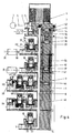
- Fig. 1 is a compressed air treatment device for automotive compressed air systems shown schematically common housing 1 can be seen in or on the essential Elements of the processing device are housed.
- the housing 1 has a connection 2, to which one of connected to a compressor 3 connecting line 4 is.
- the connection 2 leads to a distribution space 5, of which the compressed air brought in on the one hand via an air dryer 6 flows and arrives in front of a check valve 7. at Opened check valve 7, the compressed air enters Central bore 8, to which the individual circles are connected are.
- a Integrated pressure regulator 10 which here as an electrical pressure regulator is trained.
- the pressure regulator 10 has an outlet valve 11 whose piston 12 is supported on a closing spring 13.
- the outlet valve 11 includes a solenoid valve 14, which with Compressed air is supplied from the central bore 8, its own Vent port 15 and over the compressed air a line 16 can reach an actuating piston 17 in order to open the exhaust valve 11.
- the invention can also be used when only a multi-circuit protection valve or preferably a multi-circuit protection valve 9 is arranged in a housing 1 and for example an air dryer 6 and a pressure regulator 10 in one other part of the device can be realized.
- the overflow valve 18 has a movable wall 20, here in the form of a step piston 21 is realized.
- the movable wall 20 and the Step piston 21 has a first active surface 22 on the inflow side on, in front of which an inflow space 23 is formed, which over the Line 19 in permanent connection to the central bore 8 stands.
- the movable wall 20 or the stepped piston 21 carries on the front side a sealing plate 24 with a retracted Edge 25 forms a passage valve 24, 25.
- the stepped piston 21 has a seal 26, so that the active surface 22 between this seal 26 and the retracted edge 25 is limited.
- the stepped piston 21 has a second active surface 27, which of surrounded the retracted edge 25 as a circular area and thus is set. This second active surface 27 is continuously on the outflow side acted upon, d. H. from it leads a line 28 a connection 29 to a reservoir 30, the circuit I assigned.
- the stepped piston 21 or the movable wall 20 is on the back facing away from the inflow chamber 23 on a Supported spring 31, the bearing side and over a spring plate with adjustable adjustment screw can be. Connected by the set force of the spring 31 with the dimensioning of the first effective surface 22 Opening pressure of the overflow valve 18 is set at which the passage valve 24, 25 opens.
- the stepped piston 21 or the movable wall 20 has one further seal 32 on a stepped part with an enlarged Diameter is formed. Between the seals 26 and 32, a third active surface 33 is realized. This too third active surface 33 is on the flow chamber 23 facing Side of the step piston 21 arranged.
- the spring 31 is in one Rear room 34 arranged.
- On the step piston 21 or the movable one Wall 20 is a fourth after the rear space 34 Effective area 35 is provided. The four effective areas are for clarification 22, 27, 33, 35 on the overflow valve 18 of the circuit II shown again separately.
- the two overflow valves 18 of circuits I and II are two Solenoid valves 36 and 37 assigned. It is understood that the Assignment to only one overflow valve 18 of circuit I. can apply.
- the solenoid valve 36 is the third active surface 33 assigned.
- the solenoid valve 37 is the fourth active surface 35 assigned.
- the solenoid valve 36 is used for arbitrary opening of the overflow valve 18, here the two overflow valves 18 Circles I and II.
- a supply line leads from the central bore 8 38 to the solenoid valve 36. With this solenoid valve 36 is one which, as shown in FIG. 1, is closed in the de-energized state, i.e. the supply line 38 cordoned off while simultaneously the third Active surfaces 33 leading lines 39 through a common Vent line 40 are connected to the atmosphere.
- the situation is similar with the solenoid valve 37.
- the solenoid valve 37 is through a supply line 41 from the central bore 8 supplied with compressed air after the check valve 7 branches or starts. Lines lead from the solenoid valve 37 42 to the fourth active surface 35 on the two overflow valves of circles I and II.
- the fourth effective area is 35 provided on the outflow side, that is in the region of the rear space 34 and is thus on the other side of the movable wall 20 compared to the third effective area 33.
- the solenoid valve 37 is used to arbitrarily close the overflow valves Circles I and II. The combination is shown here in FIG. 1, in which the third and fourth active surfaces 33, 35 on different Sides of the movable wall 21 of the relief valves 18 are arranged.
- two solenoid valves 36, 37 used, both of which are closed when de-energized, shut off the supply lines 38 and 41.
- the pressure regulator 10 is on has its own solenoid valve 43, ie a separate solenoid valve 43 in addition to solenoid valves 36 and 37.
- the solenoid valve 36 which is used to open the overflow valves at will 18 of circles I and II serves, additionally fulfills the function of controlling a regeneration via a Regeneration line 44, in which a check valve 45 is arranged is. It is understood that this is just an additional one Function of the solenoid valve 36 is, which are also eliminated or also can be realized in another way.
- the circuit III also has an overflow valve 18 with limited Backflow on.
- This overflow valve 18 has in addition to two active surfaces 22 and 27, the third active surface 33, not but the fourth effective area 35.
- the overflow valve 18 des Circuit III is assigned a further solenoid valve 46, which in addition to and independently of the solenoid valves 36 and 37 is provided.
- the solenoid valve 46 serves the overflow valve 18 of the circle III open if necessary. This opening regardless of an opening of the overflow valves 18 Circles I and II take place via the solenoid valve 36.
- the overflow valve 18 of the circle III can a pressure limiter 47 downstream.
- the pressure limiter 47 has a piston 48 on which is supported on a limiting spring 49. Also the The force of the limiting spring 49 can be made adjustable.
- the piston 48 of the pressure limiter 47 is fixed to the housing stored insert 50 which, as shown in the drawing can be seen, sealed and arranged.
- the piston 48 forms an edge 51 of the insert body 50 Pass valve for compressed air, which is connected via a line 52 from the Overflow valve 18 is brought up. From the pressure limiter 47 here leads a line 28 to the reservoir in question 30 of the circle in question (not shown).
- the limit spring 49 is housed in an actuating space 53.
- the Actuating space 53 is connected via a connecting line 54 to the Effective area of the third effective area 33 of the overflow valve in question 18 connected, so that a switching movement of the Solenoid valve 46 also on the downstream pressure limiter 47 effect.
- the circle IV is designed, namely with an overflow valve 18 and a downstream one Pressure limiter 47.
- the circuit V has an overflow valve 18 with limited backflow in a normal design. It's just that realized two effective surfaces 22 and 27. At the circle V can the vehicle's air suspension must be connected.
- Fig. 1 shows an embodiment in which all solenoid valves 36, 37, 43, 46 are such solenoid valves that are closed when de-energized are.
- This relates in particular to the solenoid valve 36 to open the overflow valves 18 of the circles I and II and on the solenoid valve 37 for closing the overflow valves 18 of the Circles I and II.
- the third effective area 33 and the fourth effective area 35 are on different sides of the movable wall 20 arranged.
- the solenoid valve 36 is excited Position transferred before the normal opening pressure of the relief valves 18 of districts I and II is reached.
- the third active surface 33 applied additional force open the Overflow valves 18 of circuits I and II before reaching Opening pressure, so that the reservoir 30 of the circles I and II prefers to be replenished while maintaining the circles III to V have not yet been filled.
- the storage containers of the Circles III to V are only filled with compressed air when the opening pressures of the overflow valves 18 of these circles III to V are exceeded.
- the solenoid valve 36 can be switched over again, because then anyway Overflow valves 18 remain in the open position.
- the solenoid valve 46 of the circuit III can be operated via the control device 55.
- the arbitrary opening of the solenoid valves 18 of circuits I and II via the solenoid valve 36 and the arbitrary closing via the Solenoid valve 37 can not only be used when filling is preferred but also in other situations, for example when a leak in one of the two service brake circuits I or II occurs. It may then become necessary to do this in a targeted manner allow an air exchange between individual circles, so the corresponding switchover of the Allow solenoid valves 36 and 37 for a short time or for longer.
- FIG. 2 shows a further embodiment of a compressed air treatment device depicted in wide areas similar to the embodiment of FIG. 1 and is built, which is why on the description of the arrangement there and mode of action can be pointed out.
- the solenoid valve 37 does not only serve here Circles I and II, but also circles III and IV.
- the third effective area 33 and the fourth effective area 35 are here, too, on different sides of the movable wall 20 arranged, as also in the embodiment of FIG. 1 is the case. All solenoid valves, especially the solenoid valves 36 and 37 are those that are closed when de-energized, as shown in Fig. 2.
- the mode of operation of the compressed air treatment device according to Fig. 2 allows a particularly fast preferred filling of the circuit V of the air suspension by driving the solenoid valve 37 and is brought into the excited state. With that the overflow valves 18 of the circles I to IV closed for so long held until the preferred filling of the circle V is completed is. After that, there are those already described Switching options in a corresponding manner.
- the solenoid valve 36 is used here for the arbitrary opening of the Overflow valves 18 of circuits I and II.
- Solenoid valve 37 is used to arbitrarily close the overflow valves 18 of the Circles I, II and IV.
- the solenoid valve 46 is used to open the Overflow valve 18 of the circuit III with simultaneous application of the pressure limiter 47.
- the overflow valves 18 of the Circles I, II and III have the third effective area 33.
- the Overflow valves 18 of circuits I, II and IV have the fourth Effective area 35. It can be seen that here is the third effective area 33 and the fourth active surface 35 on the same side of the movable wall 20 or the stepped piston 21, namely on the inflow side, are provided.
- the solenoid valve 36 which can be opened the overflow valve 18 is one that is de-energized closed is.
- the solenoid valve 37 which is used to close the Overflow valves of circuits I, II and IV is one such which is open when de-energized.
- the solenoid valve 37 When switching the solenoid valve 37, the additional force of the fourth effective area 35 removed.
- the solenoid valve 37 can thus also referred to as an indirectly working solenoid valve become.
- the solenoid valve 36 is used for arbitrarily opening the overflow valves 18 of the two Circles I and II. It is a solenoid valve 36 which is open when de-energized.
- the solenoid valve 37 is used to close the overflow valves 18 of the circuits I to IV is a solenoid valve 37 which is closed when de-energized is shut off the connecting line and the ventilation brings about the relevant active surface 35 in this position or allows. It can be seen that the active surfaces 33 and 35 on the same side of the movable wall 20, namely on the Side of the rear space 34 are arranged.
- Solenoid valve 36 also serves to control a regeneration phase, and via a relay valve 56. This additional function too is compatible with the main function of the solenoid valve 36, namely the arbitrary opening of the overflow valves 18 Circles I and II.
- the embodiment of the compressed air treatment device according to 5 shows a further variation possibility of the overflow valves 18 of circles I and II.
- the solenoid valve 37 is used for Closing the overflow valves 18 of the circuits I to IV.
- the solenoid valve 46 of FIGS. 1 and 2 serves to open the overflow valve 18 of district III.
- the active surfaces 33, 35 are here different sides of the movable wall 20 of the relief valves 18 arranged.
- Solenoid valves 36 and 37 are here those that are open when de-energized. Deviating from this is appropriate the pressure regulator 10 is controlled via the solenoid valve 43, which is closed without current. It is understood that at all embodiments of the pressure regulator 10 and / or the dryer 6 can also be omitted, so that in such a case Compressed air distribution device is present.
Landscapes
- Engineering & Computer Science (AREA)
- Mechanical Engineering (AREA)
- Transportation (AREA)
- Chemical & Material Sciences (AREA)
- Analytical Chemistry (AREA)
- General Chemical & Material Sciences (AREA)
- Oil, Petroleum & Natural Gas (AREA)
- Chemical Kinetics & Catalysis (AREA)
- Vehicle Body Suspensions (AREA)
- Fluid-Pressure Circuits (AREA)
Abstract
Description
- Fig. 1
- eine schematisierte Schnittdarstellung durch eine Druckluftaufbereitungseinrichtung mit der Darstellung der für die Realisierung der Erfindung wesentlichen Elemente,
- Fig. 2
- eine ähnliche Schnittdarstellung wie Fig. 1, jedoch bei einer zweiten Ausführungsform,
- Fig. 3
- eine dritte Ausführungsform einer Druckluftaufbereitungseinrichtung,
- Fig. 4
- eine vierte Ausführungsform einer Druckluftaufbereitungseinrichtung, und
- Fig. 5
- eine fünfte Ausführungsform einer Druckluftaufbereitungseinrichtung.
- 1 -
- Gehäuse
- 2 -
- Anschluss
- 3 -
- Kompressor
- 4 -
- Verbindungsleitung
- 5 -
- Verteilungsraum
- 6 -
- Lufttrockner
- 7 -
- Rückschlagventil
- 8 -
- Zentralbohrung
- 9 -
- Mehrkreisschutzventil
- 10 -
- Druckregler
- 11 -
- Auslassventil
- 12 -
- Kolben
- 13 -
- Schließfeder
- 14 -
- Magnetventil
- 15 -
- Entlüftungsanschluss
- 16 -
- Leitung
- 17 -
- Betätigungskolben
- 18 -
- Überströmventil
- 19 -
- Leitung
- 20 -
- bewegliche Wand
- 21 -
- Stufenkolben
- 22 -
- erste Wirkfläche
- 23 -
- Anströmraum
- 24 -
- Dichtungsplatte
- 25 -
- Rand
- 26 -
- Dichtung
- 27 -
- zweite Wirkfläche
- 28 -
- Leitung
- 29 -
- Anschluss
- 30 -
- Vorratsbehälter
- 31 -
- Feder
- 32 -
- Dichtung
- 33 -
- dritte Wirkfläche
- 34 -
- Rückraum
- 35 -
- vierte Wirkfläche
- 36 -
- Magnetventil
- 37 -
- Magnetventil
- 38 -
- Versorgungsleitung
- 39 -
- Leitung
- 40 -
- Entlüftungsleitung
- 41 -
- Versorgungsleitung
- 42 -
- Leitungen
- 43 -
- Magnetventil
- 44 -
- Regenerationsleitung
- 45 -
- Rückschlagventil
- 46 -
- Magnetventil
- 47 -
- Druckbegrenzer
- 48 -
- Kolben
- 49 -
- Begrenzungsfeder
- 50 -
- Einsatzkörper
- 51 -
- Rand
- 52 -
- Leitung
- 53 -
- Betätigungsraum
- 54 -
- Verbindungsleitung
- 55 -
- Steuereinrichtung
- 56 -
- Relaisventil
Claims (9)
- Druckluftverteilungseinrichtung für Kraftfahrzeug-Druckluftanlagen, mit einem Mehrkreisschutzventil (9) und vorzugsweise einem Druckregler (10) und einem Lufttrockner (6), wobei das Mehrkreisschutzventil (9) für mehrere Kreise je ein Überströmventil (18) mit begrenzter Rückströmung und mindestens zwei Magnetventile (36, 37) mit eigenem Entlüftungsanschluss beinhaltet, jedes Überströmventil (18) eine bewegliche Wand (20) aufweist, die einen Anströmraum (23) von einem Rückraum (34) mit Feder (31) abteilt, und die bewegliche Wand (20) zumindest eines Überströmventils (18) eines Kreises außer den beiden anströmseitigen Wirkflächen (22, 27) eine weitere über eines der Magnetventile (36, 37) beaufschlagbare dritte Wirkfläche (33) aufweist, dadurch gekennzeichnet, dass zumindest das die dritte Wirkfläche (33) aufweisende Überströmventil (18) eines Kreises eine vierte Wirkfläche (35) aufweist, die über ein anderes als das der dritten Wirkfläche (33) zugeordnete Magnetventil (36) ansteuerbar ist, und dass das der dritten Wirkfläche (33) zugeordnete Magnetventil (36) zum Öffnen des Überströmventils (18) und das der vierten Wirkfläche (35) zugeordnete Magnetventil (37) zum Schließen des Überströmventils (18) des Kreises ausgebildet ist.
- Druckluftverteilungseinrichtung nach Anspruch 1, dadurch gekennzeichnet, dass die dritte Wirkfläche (33) auf der einen Seite der beweglichen Wand (20) des Überströmventils (18) und die vierte Wirkfläche (35) auf der anderen Seite der beweglichen Wand (20) des Überströmventils (18) angeordnet sind und dass die beiden der dritten und der vierten Wirkfläche (33, 35) zugeordneten Magnetventile (36, 37) stromlos zu oder stromlos offen ausgebildet sind.
- Druckluftverteilungseinrichtung nach Anspruch 1, dadurch gekennzeichnet, dass die dritte Wirkfläche (33) und die vierte Wirkfläche (35) auf der gleichen Seite der beweglichen Wand (20) des Überströmventils (18) angeordnet sind und dass das eine Magnetventil (36) stromlos zu und das andere Magnetventil (37) stromlos offen ausgebildet ist.
- Druckluftverteilungseinrichtung nach einem oder mehreren der Ansprüche 1 bis 3, dadurch gekennzeichnet, dass das der dritten Wirkfläche (33) zugeordnete Magnetventil (36) und/oder das der vierten Wirkfläche (35) zugeordnete Magnetventil (37) zur Ansteuerung mindesten zweier Überströmventile (18) zweier Kreise ausgebildet ist.
- Druckluftverteilungseinrichtung nach Anspruch 4, dadurch gekennzeichnet, dass das der dritten Wirkfläche (33) zugeordnete Magnetventil (36) und das der vierten Wirkfläche (35) zugeordnete Magnetventil (37) zur Ansteuerung der beiden Kreise I und II ausgebildet sind.
- Druckluftverteilungseinrichtung nach einem oder mehreren der Ansprüche 1 bis 5, dadurch gekennzeichnet, dass die bewegliche Wand (20) des Überströmventils (18), dem zwei Magnetventile (36, 37) zur Ansteuerung zugeordnet sind, als Stufenkolben (21) ausgebildet ist.
- Druckluftverteilungseinrichtung nach Anspruch 5, dadurch gekennzeichnet, dass neben den beiden Magnetventilen (36, 37), die der oder den dritten Wirkflächen (33) und der oder den vierten Wirkflächen (35) zugeordnet sind, ein drittes Magnetventil (46) zum Öffnen des Überströmventils (18) des Kreises III unterhalb des eingestellten Öffnungsdruckes vorgesehen ist.
- Druckluftverteilungseinrichtung nach Anspruch 7, dadurch gekennzeichnet, dass einem oder mehreren der Überströmventile (18) ein Druckbegrenzer (47) nachgeschaltet ist, der einen in Öffnungsrichtung auf einer Begrenzungsfeder (49) abgestützten Kolben (48) und auf der der Begrenzungsfeder (49) zugekehrten Seite eine Betätigungsfläche aufweist, deren Betätigungsraum (53) über eine Verbindungsleitung (54) an den Wirkraum der dritten Wirkfläche (33) des Überströmventils (18) angeschlossen ist.
- Druckluftverteilungseinrichtung nach einem oder mehreren der Ansprüche 1 bis 8, dadurch gekennzeichnet, dass das der vierten Wirkfläche (35) zugeordnete Magnetventil (37) zur Ansteuerung der Überströmventile (18) der Kreise I bis IV ausgebildet ist.
Applications Claiming Priority (2)
| Application Number | Priority Date | Filing Date | Title |
|---|---|---|---|
| DE2002120791 DE10220791A1 (de) | 2002-05-10 | 2002-05-10 | Druckluftverteilungseinrichtung für Kfz-Druckluftanlagen |
| DE10220791 | 2002-05-10 |
Publications (2)
| Publication Number | Publication Date |
|---|---|
| EP1361132A1 true EP1361132A1 (de) | 2003-11-12 |
| EP1361132B1 EP1361132B1 (de) | 2005-07-27 |
Family
ID=29225132
Family Applications (1)
| Application Number | Title | Priority Date | Filing Date |
|---|---|---|---|
| EP03010298A Expired - Lifetime EP1361132B1 (de) | 2002-05-10 | 2003-05-07 | Druckluftverteilungseinrichtung für Kfz-Druckluftanlagen |
Country Status (3)
| Country | Link |
|---|---|
| US (1) | US6868866B2 (de) |
| EP (1) | EP1361132B1 (de) |
| DE (2) | DE10220791A1 (de) |
Cited By (3)
| Publication number | Priority date | Publication date | Assignee | Title |
|---|---|---|---|---|
| WO2008025403A1 (de) * | 2006-08-31 | 2008-03-06 | Wabco Gmbh | Pneumatisches modul |
| EP2050596A1 (de) * | 2007-10-20 | 2009-04-22 | WABCO GmbH | Elektronische Luftaufbereitungsanlage |
| WO2010149244A1 (de) * | 2009-06-23 | 2010-12-29 | Wabco Gmbh | Druckluftversorgungssystem für einen druckluftverbraucherkreis, insbesondere für ein luftfederungssystem |
Families Citing this family (5)
| Publication number | Priority date | Publication date | Assignee | Title |
|---|---|---|---|---|
| DE10333182A1 (de) | 2003-07-22 | 2005-02-10 | Daimlerchrysler Ag | Anhänger- und Aufliegerbremsventil mit integrierter Ansteuerung der Luftfederung |
| DE10338162B3 (de) † | 2003-08-20 | 2005-06-02 | Haldex Brake Products Gmbh | Verfahren zum Betreiben einer Druckluftbeschaffungsanlage eines Kraftfahrzeuges sowie Druckluftaufbereitungseinrichtung |
| JP5336400B2 (ja) | 2010-02-04 | 2013-11-06 | ナブテスコオートモーティブ株式会社 | 車両用圧縮空気供給装置 |
| DE102010044910A1 (de) | 2010-09-09 | 2012-03-15 | Knorr-Bremse Systeme für Nutzfahrzeuge GmbH | Luftaufbereitungseinrichtung und Fahrzeug mit einer Luftaufbereitungseinrichtung |
| US9375679B2 (en) | 2013-08-30 | 2016-06-28 | Haldex Brake Products Corporation | Air dryer assembly with manifold system |
Citations (3)
| Publication number | Priority date | Publication date | Assignee | Title |
|---|---|---|---|---|
| DE3603742A1 (de) * | 1985-02-06 | 1986-08-14 | Aisin Seiki K.K., Kariya, Aichi | Hydraulik-pumpen-aufbau in verbindung mit einem speicher |
| DE19710814C1 (de) * | 1997-03-15 | 1998-07-09 | Grau Gmbh | Druckluftaufbereitungseinrichtung für Druckluftbeschaffungsanlagen auf Kraftfahrzeugen |
| DE19854205A1 (de) * | 1998-11-24 | 2000-05-31 | Haldex Brake Prod Gmbh & Co Kg | Mehrkreisschutzventil für Druckluftbeschaffungsanlagen von Kraftfahrzeugen |
Family Cites Families (8)
| Publication number | Priority date | Publication date | Assignee | Title |
|---|---|---|---|---|
| DE4421575C2 (de) | 1994-06-21 | 1997-07-03 | Grau Gmbh | Druckregler für Druckluftbeschaffungsanlagen von Kraftfahrzeugen |
| DE19515895A1 (de) * | 1995-04-29 | 1996-10-31 | Bosch Gmbh Robert | Druckluft-Versorgungseinrichtung für Fahrzeug-Druckluftanlagen sowie Verfahren zum Steuern der Druckluft-Versorgungseinrichtung |
| DE19544621C1 (de) | 1995-11-30 | 1997-01-30 | Grau Gmbh | Druckluftaufbereitungseinrichtung für Kraftfahrzeug-Druckluftanlagen |
| US5678900A (en) * | 1995-12-19 | 1997-10-21 | Grau Gmbh | Unloader for a source of air under pressure on vehicles |
| DE19700243C1 (de) * | 1997-01-07 | 1998-04-02 | Grau Gmbh | Druckluftaufbereitungseinrichtung für Kraftfahrzeug-Druckluftanlagen |
| DE19710059C1 (de) * | 1997-03-12 | 1998-07-09 | Grau Gmbh | Druckluftaufbereitungseinrichtung für Druckluftbeschaffungsanlagen auf Kraftfahrzeugen |
| DE19835638A1 (de) * | 1998-08-06 | 2000-02-17 | Knorr Bremse Systeme | Elektronische Druckluftaufbereitungsanlage |
| US6340034B1 (en) * | 2000-02-09 | 2002-01-22 | Daniel A. Holt | Gas regulator with multiple regulated outlet ports |
-
2002
- 2002-05-10 DE DE2002120791 patent/DE10220791A1/de not_active Withdrawn
-
2003
- 2003-05-07 EP EP03010298A patent/EP1361132B1/de not_active Expired - Lifetime
- 2003-05-07 DE DE50300836T patent/DE50300836D1/de not_active Expired - Lifetime
- 2003-05-09 US US10/434,538 patent/US6868866B2/en not_active Expired - Fee Related
Patent Citations (3)
| Publication number | Priority date | Publication date | Assignee | Title |
|---|---|---|---|---|
| DE3603742A1 (de) * | 1985-02-06 | 1986-08-14 | Aisin Seiki K.K., Kariya, Aichi | Hydraulik-pumpen-aufbau in verbindung mit einem speicher |
| DE19710814C1 (de) * | 1997-03-15 | 1998-07-09 | Grau Gmbh | Druckluftaufbereitungseinrichtung für Druckluftbeschaffungsanlagen auf Kraftfahrzeugen |
| DE19854205A1 (de) * | 1998-11-24 | 2000-05-31 | Haldex Brake Prod Gmbh & Co Kg | Mehrkreisschutzventil für Druckluftbeschaffungsanlagen von Kraftfahrzeugen |
Cited By (5)
| Publication number | Priority date | Publication date | Assignee | Title |
|---|---|---|---|---|
| WO2008025403A1 (de) * | 2006-08-31 | 2008-03-06 | Wabco Gmbh | Pneumatisches modul |
| EP2050596A1 (de) * | 2007-10-20 | 2009-04-22 | WABCO GmbH | Elektronische Luftaufbereitungsanlage |
| WO2010149244A1 (de) * | 2009-06-23 | 2010-12-29 | Wabco Gmbh | Druckluftversorgungssystem für einen druckluftverbraucherkreis, insbesondere für ein luftfederungssystem |
| RU2536000C2 (ru) * | 2009-06-23 | 2014-12-20 | Вабко Гмбх | Система, снабженная сжатым воздухом, контура потребителя сжатого воздуха, в частности пневмоподвески |
| US9783019B2 (en) | 2009-06-23 | 2017-10-10 | Wabco Gmbh | Compressed air supply system for a compressed air consumer circuit |
Also Published As
| Publication number | Publication date |
|---|---|
| US20030209276A1 (en) | 2003-11-13 |
| EP1361132B1 (de) | 2005-07-27 |
| DE10220791A1 (de) | 2003-11-27 |
| DE50300836D1 (de) | 2005-09-01 |
| US6868866B2 (en) | 2005-03-22 |
Similar Documents
| Publication | Publication Date | Title |
|---|---|---|
| EP3724013B1 (de) | Druckluftversorgungsanlage zum betreiben einer pneumatikanlage, verfahren und fahrzeug | |
| DE3006771C2 (de) | ||
| EP3724515B1 (de) | Druckluftversorgungsanlage zum betreiben einer pneumatikanlage, verfahren und fahrzeug | |
| EP0031082B1 (de) | In Kraftfahrzeugen zu verwendendes Mehrkreisschutzventil | |
| DE19821420C1 (de) | Druckluftaufbereitungseinrichtung für Druckluftbeschaffungsanlagen auf Kraftfahrzeugen | |
| DE3434884C2 (de) | Schutzsystem für eine Kraftfahrzeug-Druckluftanlage | |
| DE1916266A1 (de) | Elektrohydraulisches Stellgeraet | |
| EP1508488B2 (de) | Verfahren zum Betreiben einer Druckluftbeschaffungsanlage eines Kraftfahrzeuges sowie Druckluftaufbereitungseinrichtung | |
| DE19918070B4 (de) | Druckregelvorrichtung für elektro-pneumatische Bremsanlagen von Fahrzeugen, insbesondere Nutzfahrzeugen | |
| EP1361131B1 (de) | Druckluftaufbereitungseinrichtung für Kfz-Druckluftanlagen | |
| EP1361132B1 (de) | Druckluftverteilungseinrichtung für Kfz-Druckluftanlagen | |
| DE19710814C1 (de) | Druckluftaufbereitungseinrichtung für Druckluftbeschaffungsanlagen auf Kraftfahrzeugen | |
| EP2171287B1 (de) | Vorrichtung zum stellen eines aktuators | |
| DE10220790C1 (de) | Druckluftaufbereitungseinrichtung für Kfz-Druckluftanlagen | |
| DE10158065A1 (de) | Redundanzdruck-Umschaltventil für elektronisch-pneumatische Bremsanlage | |
| EP2789512B1 (de) | Druckluftaufbereitungseinrichtung für ein Nutzfahrzeug | |
| EP1018460B1 (de) | Mehrkreisschutzventil für Druckluftbeschaffungsanlagen von Kraftfahrzeugen | |
| DE2929578C2 (de) | ||
| EP0717201B1 (de) | Schutzsystem für eine Druckmittelanlage | |
| EP2371644B1 (de) | Druckluftanlage | |
| EP2222965A1 (de) | Ventilvorrichtung | |
| DE102016212306A1 (de) | Zwischenblock und Kompaktachse mit einem Zwischenblock | |
| DE4125964C1 (en) | Braking system in vehicle - has multi-circuit safety valve using piston with three parallel working surfaces | |
| DE2701960C2 (de) | Stufbares Handbremsventil | |
| DE2754219B2 (de) | Mehrkreisschutzventil für Bremsanlagen von Kraftfahrzeugen |
Legal Events
| Date | Code | Title | Description |
|---|---|---|---|
| PUAI | Public reference made under article 153(3) epc to a published international application that has entered the european phase |
Free format text: ORIGINAL CODE: 0009012 |
|
| AK | Designated contracting states |
Kind code of ref document: A1 Designated state(s): AT BE BG CH CY CZ DE DK EE ES FI FR GB GR HU IE IT LI LU MC NL PT RO SE SI SK TR |
|
| AX | Request for extension of the european patent |
Extension state: AL LT LV MK |
|
| 17P | Request for examination filed |
Effective date: 20040511 |
|
| AKX | Designation fees paid |
Designated state(s): DE FR IT |
|
| 17Q | First examination report despatched |
Effective date: 20040806 |
|
| GRAP | Despatch of communication of intention to grant a patent |
Free format text: ORIGINAL CODE: EPIDOSNIGR1 |
|
| GRAS | Grant fee paid |
Free format text: ORIGINAL CODE: EPIDOSNIGR3 |
|
| GRAA | (expected) grant |
Free format text: ORIGINAL CODE: 0009210 |
|
| AK | Designated contracting states |
Kind code of ref document: B1 Designated state(s): DE FR IT |
|
| REF | Corresponds to: |
Ref document number: 50300836 Country of ref document: DE Date of ref document: 20050901 Kind code of ref document: P |
|
| ET | Fr: translation filed | ||
| PLBE | No opposition filed within time limit |
Free format text: ORIGINAL CODE: 0009261 |
|
| STAA | Information on the status of an ep patent application or granted ep patent |
Free format text: STATUS: NO OPPOSITION FILED WITHIN TIME LIMIT |
|
| 26N | No opposition filed |
Effective date: 20060428 |
|
| REG | Reference to a national code |
Ref country code: FR Ref legal event code: PLFP Year of fee payment: 13 |
|
| PGFP | Annual fee paid to national office [announced via postgrant information from national office to epo] |
Ref country code: IT Payment date: 20150519 Year of fee payment: 13 Ref country code: FR Payment date: 20150519 Year of fee payment: 13 |
|
| REG | Reference to a national code |
Ref country code: DE Ref legal event code: R082 Ref document number: 50300836 Country of ref document: DE Representative=s name: REHBERG HUEPPE + PARTNER PATENTANWAELTE PARTG , DE Ref country code: DE Ref legal event code: R081 Ref document number: 50300836 Country of ref document: DE Owner name: HALDEX BRAKE PRODUCTS AKTIEBOLAG, SE Free format text: FORMER OWNER: HALDEX BRAKE PRODUCTS GMBH, 69123 HEIDELBERG, DE |
|
| PG25 | Lapsed in a contracting state [announced via postgrant information from national office to epo] |
Ref country code: IT Free format text: LAPSE BECAUSE OF NON-PAYMENT OF DUE FEES Effective date: 20160507 |
|
| REG | Reference to a national code |
Ref country code: FR Ref legal event code: ST Effective date: 20170131 |
|
| PG25 | Lapsed in a contracting state [announced via postgrant information from national office to epo] |
Ref country code: FR Free format text: LAPSE BECAUSE OF NON-PAYMENT OF DUE FEES Effective date: 20160531 |
|
| PGFP | Annual fee paid to national office [announced via postgrant information from national office to epo] |
Ref country code: DE Payment date: 20220408 Year of fee payment: 20 |
|
| REG | Reference to a national code |
Ref country code: DE Ref legal event code: R071 Ref document number: 50300836 Country of ref document: DE |