EP1361111A2 - Tensioning strap support - Google Patents
Tensioning strap support Download PDFInfo
- Publication number
- EP1361111A2 EP1361111A2 EP03007868A EP03007868A EP1361111A2 EP 1361111 A2 EP1361111 A2 EP 1361111A2 EP 03007868 A EP03007868 A EP 03007868A EP 03007868 A EP03007868 A EP 03007868A EP 1361111 A2 EP1361111 A2 EP 1361111A2
- Authority
- EP
- European Patent Office
- Prior art keywords
- holder
- receiving part
- tension belt
- belt
- longitudinal axis
- Prior art date
- Legal status (The legal status is an assumption and is not a legal conclusion. Google has not performed a legal analysis and makes no representation as to the accuracy of the status listed.)
- Withdrawn
Links
- 229910000639 Spring steel Inorganic materials 0.000 claims description 3
- 239000000463 material Substances 0.000 abstract description 3
- 241000047428 Halter Species 0.000 description 4
- 239000000853 adhesive Substances 0.000 description 2
- 230000001070 adhesive effect Effects 0.000 description 2
- 230000001419 dependent effect Effects 0.000 description 1
- 238000003780 insertion Methods 0.000 description 1
- 230000037431 insertion Effects 0.000 description 1
- 239000002184 metal Substances 0.000 description 1
- 239000011347 resin Substances 0.000 description 1
- 229920005989 resin Polymers 0.000 description 1
- 239000000725 suspension Substances 0.000 description 1
- 230000001960 triggered effect Effects 0.000 description 1
Images

Classifications
-
- B—PERFORMING OPERATIONS; TRANSPORTING
- B60—VEHICLES IN GENERAL
- B60P—VEHICLES ADAPTED FOR LOAD TRANSPORTATION OR TO TRANSPORT, TO CARRY, OR TO COMPRISE SPECIAL LOADS OR OBJECTS
- B60P7/00—Securing or covering of load on vehicles
- B60P7/06—Securing of load
- B60P7/08—Securing to the vehicle floor or sides
- B60P7/0823—Straps; Tighteners
- B60P7/0853—Tools for manipulating straps or tighteners
-
- B—PERFORMING OPERATIONS; TRANSPORTING
- B60—VEHICLES IN GENERAL
- B60P—VEHICLES ADAPTED FOR LOAD TRANSPORTATION OR TO TRANSPORT, TO CARRY, OR TO COMPRISE SPECIAL LOADS OR OBJECTS
- B60P7/00—Securing or covering of load on vehicles
- B60P7/06—Securing of load
- B60P7/08—Securing to the vehicle floor or sides
- B60P7/0823—Straps; Tighteners
Definitions
- the invention relates to a holder for tension belts according to the preamble of the claim 1.
- the invention has for its object to find a solution with the Load can be secured easily and safely.
- a lashing strap is not placed over the load until the loading area has been loaded should be, but that the lashing strap is already above the for the Load space available should be designed. Because the hold of the Transport vehicles can be surrounded on the sides and above by holding rods These linkage holders are arranged to hold the lashing strap during loading hold. After placing the load, the tension belt is removed from the Holders dropped onto the load.
- the holders In a second inventive step it was recognized that the holders must include a release device which due to a sufficiently high tension on the tension belt or possibly due to another release actuation the belt transversely to its longitudinal direction let out the holder.
- the holder comprises a fastening device 8 for attaching the holder to a linkage and a receiving part with a receiving area extending along a longitudinal axis for receiving a lashing strap and with a release device which the lashing strap can release from the holder transversely to the longitudinal axis.
- an im Section of the c-shaped receiving part possibly partially made of spring material, in particular Spring steel, provided so that the strap at the open section of the c-shaped Receiving part can be pulled out, the free ends of the C-shaped part may move resiliently away from the continuous area and thus allow the belt to exit.
- the release facility will thus from the open section and / or the resilient free ends of the c-shaped Receiving part formed.
- the holder In addition to the receiving part for the belt, the holder must have a fastening device include with which it can be attached to a part of the support rod.
- a tension in the transverse direction of the loading area is, for example, at a upper crossbar of the support rod two holders arranged.
- the tension belt is guided through these two holders or inserted into them. This allows the Strap on one side of the vehicle attached to the vehicle and by the two brackets held above the cargo to the other side of the vehicle.
- the release device allows it to be dropped of the belt on the load.
- the free end of the belt pulled into a tensioning device at the free end of a short tension belt section is arranged.
- the short tension belt section is with the other End hung on a hanging element and together with the over the Loaded belt tensioned.
- the fastening device comprises a contact area for contacting one Linkage area and a fixing device for fixing the contact area.
- the contact area is, for example, form-fitting to the linkage area customized. In the case of a rod in the form of a rectangular profile, the contact area is about a rectangular profile with an open side so that it is on the linkage can be attached.
- the fixing device includes, for example at least one clamping screw, but possibly also at least one Latching. With a clamping screw, the holder on the linkage is immovable set. To attach and remove a holder, the Screw a little bit in or out.
- a locking device with a locking element can be designed so that the holder is attached to the linkage and can optionally be moved along the linkage.
- FIG. 1 shows a transport vehicle 1 with a loading area 2 and a holding rod 3, which vertical columns 3a, horizontal side members 3b and horizontal cross members includes.
- the holding rod 3 is used to carry a closing the cargo space Blache.
- the tension belt 5 is approximately by two at an end portion of the cross member 3c arranged holder 4 out, or inserted into this.
- On one side of the vehicle the tension belt 5 is fastened to the vehicle 1 via a connection arrangement 6. When load 7 is placed under the tension belt 5 on the loading surface 2, the tension belt dropped from the holders onto the load.
- Holder 4 a release device, which due to a sufficiently high train at the free end 5a of the tension belt 5 or possibly due to another Release the belt to emerge from the two holders 4. Subsequently the free end of the tension belt 5 in a not shown Tensioner retracted at the free end of a short strap section is arranged. The short tension belt section is with the other End hung on a suspension element 6a and together with the over Load 7 placed tension belt 5 tensioned.
- Fig. 2 shows a holder 4 with a tension belt section 5a held therein.
- the holder 4 comprises a C-shaped section, the strap 5a partially enclosing the receiving part 4a, which optionally partially, but preferably completely, from spring material, in particular made of spring steel.
- the receiving part 4a forms a Cross-section slit-shaped receiving area for receiving a tape.
- the Tension belt can from the open section 4b of the c-shaped receiving part 4a the holder 4 are pulled out, the free ends of the c-shaped part move resiliently as spring lips 4f away from the continuous area and so enable or facilitate the exit of the tension belt 5a.
- the receiving part 4a is slightly wider than the tension belt 5a, often tension belts 5 with a width of 50mm can be used.
- the spring property of the spring lips 4f and Size of the open section 4b of the c-shaped receiving part 4a must be so be chosen that the tension belt 5a is held sufficiently on the side and if necessary, can be tightened by the holder 4 without leaving the holder 4 to jump.
- the spring property of the spring lips 4f and / or the edge shape and the The size of the open section 4b must also be chosen so that an am one end of the fastening strap 5 by pulling the free end out of the holder 4 can be torn.
- the open section 4b preferably has a width in the range from 10 to 30 mm, but especially from 15 to 25mm.
- the open section preferably extends over an area from 20 to 60%, but in particular from 35 to 57%, of the width of the receiving part 4a. In the illustrated embodiment, the open section 4b is in the middle of the receiving part 4a arranged.
- the open Section 4b can also be formed displaced towards one side, in that the two spring lips 4f are of different sizes.
- the Holding property of the receiving part 4a and the possibility of the tension belt Tear out the receiving part 4a also depend on the transverse stiffness of the Tension belt.
- the holder 4 are preferably designed so that they with the common tension belts achieve the desired holding and release properties.
- the holder 4, in particular the receiving part 4a has in its longitudinal direction preferably an expansion in a range from 30 to 90 mm, in particular of essentially 50mm.
- the spring lips 4f are thereby sufficiently stable to survive a large number of tear-out cycles without damage or breakage.
- the holder 4 comprises a fastening device 8, with which it can be attached to part of the holding rod 3 can.
- the fastening device 8 shown includes a form-fitting the rod area adapted contact area 8a in the form of a rectangular profile with an open side so that it fits onto a rectangular profile of the boom 3 can be plugged on.
- the fastening device 8 comprises a fastening device, for example at least a thread with a clamping screw 8b, which is screwed against the rod 3 becomes.
- the fastening device 8 is in the example shown with a Welded or soldered connection attached to the receiving part 4a. It goes without saying itself that a screw or rivet connection can also be used for this.
- FIG. 3 shows a holder 4, the receiving part 4a of which is two via a swivel joint 9 interconnected legs 10 and 11 comprises.
- a snap-in connection 12 for example in the form of a Push-button connection, connectable.
- the snap connection 12 is designed that a tension belt opens the snap-in connection 12 with a sufficiently high tension.
- a second leg 11 pivots below and releases the tension belt.
- a first leg 10 is with the fastening device 8 connected.
- the connection is as Swivel connection 13 formed, wherein a protruding pin of the fastening device 8 is positively attached to an opening of the first leg 10.
- the fastening device 8 is U-shaped and comprises two latching elements 14, the side when plugging the holder 4 on a rectangular profile spring out and then snap into place on the profile. To remove a holder 4 be the snap-in elements 14 are pressed somewhat outwards.
- a holder 4 according to FIG. 3 can be made at least partially of plastic. When using of plastic, its components must have a greater thickness than for a metal version.
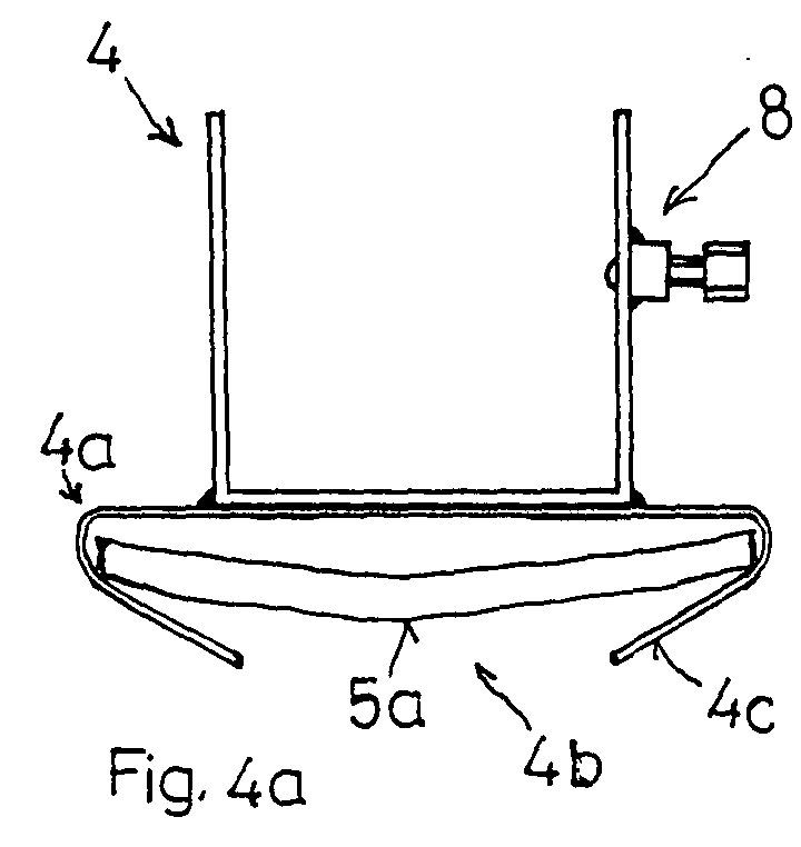
- FIG. 4a and 4b A particularly simple and practical holder 4 is shown in Fig. 4a and 4b.
- On the fastening device 8 is a c-shaped receiving part in section 4a arranged in which a tension belt section 5a is held.
- Both sides of the open section 4b adjoining fixed lips 4c hold the Tension belt back because of its transverse stiffness with small forces does not slip out of the holder 4 towards the bottom. Only with a sufficiently large one Withdrawal force, the tension belt falls out of shape under deformation in the transverse direction Receiving part 4a.
- the alignment of the fixed lips 4c and the expansion of the open section are chosen so that the inserted tension belt at the desired tensile force slides out of the receiving part 4a.
- the angle between a fixed lip 4c and the connection surface between the two lips is approximately in the range from 20 ° to 50 °, preferably from 35 ° to 47 °. It has shown, that the shape of the fixed lips 4c shown in Fig. 4c the desired Hold and release properties achieved. The width of the fixed lips 4c increases towards the open section 4b. The insertion and removal of the Tension belt is possible with little effort in the illustrated embodiment. Damage to the tension belt when pulling out is avoided.
Landscapes
- Engineering & Computer Science (AREA)
- Transportation (AREA)
- Mechanical Engineering (AREA)
- Fittings On The Vehicle Exterior For Carrying Loads, And Devices For Holding Or Mounting Articles (AREA)
- Clamps And Clips (AREA)
Abstract
Am Haltegestänge (3), das den Laderaum eines Transportfahrzeuges (1) umgibt,
werden Halter (4) angeordnet, die es ermöglichen einen Spanngurt (5, 5a) bereits
vor dem Laden über dem für das Ladegut (7) bereitstehenden Raum auszulegen
und mit dem einen Ende am Fahrzeug (1) zu befestigen. Nach dem Plazieren des
Ladegutes (7) wird der Spanngurt (5, 5a) durch ziehen am freien Ende aus den
Haltern (4) auf das Ladegut (7) fallen gelassen. Jeder Halter (4) umfasst eine Befestigungseinrichtung
(8) zum Befestigen des Halters (4) am Gestänge (3) und einen
Aufnahmeteil (4a) mit einem sich entlang einer Längsachse erstreckenden Aufnahmebereich
zum Aufnehmen eines Spanngurtes (5, 5a) sowie mit einer Freigabeeinrichtung,
welche den Spanngurt quer zur Längsachse vom Halter (4) freigeben
kann.
Description
Die Erfindung betrifft einen Halter für Spanngurte nach dem Oberbegriff des Anspruches 1.The invention relates to a holder for tension belts according to the preamble of the claim 1.
Beim Beladen der Ladefläche von Transportfahrzeugen wird das Transportgut auf der Ladefläche plaziert und anschliessend mit Spanngurten fixiert. Dabei müssen Spanngurte über das Transportgut gelegt, beidseitig fixiert und gespannt werden. Häufig ist es schwierig und zeitaufwendig einen Spanngurt über das Transportgut zu legen. Wenn dazu eine Person auf das Transportgut klettert, so ist dies gefährlich, weil das Transportgut kippen und/oder diese Person vom Transportgut fallen könnte. Wenn die Person seitlich am äussersten Rand der Ladefläche steht und versucht den Spanngurt über das Transportgut zu werfen, kann sie sich dabei nur mit einer Hand halten und es besteht die Gefahr, dass die Person das Gleichgewicht verliert, oder der Spanngurt nicht am richtigen Ort zu liegen kommt.When loading the loading area of transport vehicles, the cargo is opened placed on the loading area and then fixed with tension belts. Doing so Tension belts are placed over the goods to be transported, fixed on both sides and tensioned. It is often difficult and time-consuming to put a tension belt over the cargo to lay. If a person climbs on the cargo, this is dangerous, because the transported goods tip over and / or this person falls off the transported goods could. When the person stands at the very edge of the loading area and If she tries to throw the tension belt over the goods to be transported, she can only do so Hold it with one hand and there is a risk that the person's balance loses, or the tension belt does not come to the right place.
Aus der DE 44 15 042 ist lediglich ein einhändig einhäng- und spannbares Spannteil bekannt. Der Spanngurt muss, wie oben beschrieben, mit unerwünschtem Aufwand und Gefahren über das Transportgut gelegt werden.From DE 44 15 042 is only a one-handed hook and tension Clamping part known. The tension belt must, as described above, with undesirable Effort and risks are placed over the goods to be transported.
Der Erfindung liegt die Aufgabe zugrunde, eine Lösung zu finden mit der die Ladung einfach und gefahrlos gesichert werden kann.The invention has for its object to find a solution with the Load can be secured easily and safely.
Zur Lösung der Aufgabe wird ein Halter mit den Merkmalen des Anspruches 1 verwendet. Die abhängigen Ansprüche beschreiben alternative bzw. vorteilhafte Ausführungsvarianten.To achieve the object, a holder with the features of claim 1 is used. The dependent claims describe alternative or advantageous design variants.
Beim Lösen der Aufgabe wurde in einem ersten erfinderischen Schritt erkannt, dass
ein Spanngurt nicht erst nach dem Beladen der Ladefläche über das Ladegut gelegt
werden soll, sondern dass der Spanngurt bereits vor dem Laden über dem für das
Ladegut bereitstehenden Raum ausgelegt werden soll. Weil der Laderaum der
Transportfahrzeuge seitlich und oben von Haltegestängen umgeben ist, können an
diesen Gestängen Halter angeordnet werden, die den Spanngurt während des Beladens
halten. Nach dem Plazieren des Ladegutes wird der Spanngurt aus den
Haltern auf das Ladegut fallen gelassen. In einem zweiten erfinderischen Schritt
wurde erkannt, dass die Halter eine Auslöseeinrichtung umfassen müssen, welche
aufgrund eines genügend hohen Zuges am Spanngurt oder gegebenenfalls aufgrund
einer anderen Auslösebetätigung den Gurt quer zu seiner Längsrichtung aus
dem Halter austreten lassen. Dazu umfasst der Halter eine Befestigungseinrichtung
8 zum Befestigen des Halters an einem Gestänge und einen Aufnahmeteil mit
einem sich entlang einer Längsachse erstreckenden Aufnahmebereich zum Aufnehmen
einer Spanngurte sowie mit einer Freigabeeinrichtung, welche den Spanngurt
quer zur Längsachse vom Halter freigeben kann.When the task was solved, it was recognized in a first inventive step that
a lashing strap is not placed over the load until the loading area has been loaded
should be, but that the lashing strap is already above the for the
Load space available should be designed. Because the hold of the
Transport vehicles can be surrounded on the sides and above by holding rods
These linkage holders are arranged to hold the lashing strap during loading
hold. After placing the load, the tension belt is removed from the
Holders dropped onto the load. In a second inventive step
it was recognized that the holders must include a release device which
due to a sufficiently high tension on the tension belt or possibly due to
another release actuation the belt transversely to its longitudinal direction
let out the holder. For this purpose, the holder comprises a
Gemäss einer speziellen Ausführungsform wird für das Halten des Gurtes ein im Schnitt c-förmiger Aufnahmeteil gegebenenfalls teilweise aus Federmaterial, insbesondere Federstahl, vorgesehen, so dass der Gurt beim offenen Abschnitt des c-förmigen Aufnahmeteiles herausgezogen werden kann, wobei die freien Enden des c-förmigen Teiles sich gegebenenfalls federnd vom durchgängigen Bereich wegbewegen und so den Austritt des Gurtes ermöglichen. Die Freigabeeinrichtung wird somit vom offenen Abschnitt und/oder den federnden freien Enden des c-förmigen Aufnahmeteiles gebildet. Es versteht sich von selbst, dass auch andere einfach auszulösende Aufnahmeteile, beispielsweise solche mit unter Zug ausrastenden Elementen, mit Haftbereichen oder mit aufreissbaren Klettverbindungen vorgesehen werden können.According to a special embodiment, an im Section of the c-shaped receiving part, possibly partially made of spring material, in particular Spring steel, provided so that the strap at the open section of the c-shaped Receiving part can be pulled out, the free ends of the C-shaped part may move resiliently away from the continuous area and thus allow the belt to exit. The release facility will thus from the open section and / or the resilient free ends of the c-shaped Receiving part formed. It goes without saying that others are easy too receiving parts to be triggered, for example those with disengaging under tension Elements with adhesive areas or with tear-open Velcro connections can be.
Nebst dem Aufnahmeteil für den Gurt muss der Halter eine Befestigungseinrichtung umfassen, mit der er an einem Teil des Haltegestänges befestigt werden kann. Für eine Verspannung in Querrichtung der Ladefläche werden beispielsweise an einer oberen Querstange des Haltegestänges zwei Halter angeordnet. Der Spanngurt wird durch diese beiden Halter geführt, bzw. in diese eingelegt. Dadurch kann der Spanngurt auf einer Fahrzeugseite am Fahrzeug befestigt und von den beiden Haltern oberhalb des Ladegutes gehalten zur anderen Fahrzeugseite geführt werden. Nach dem Plazieren des Ladegutes ermöglicht die Auslöseeinrichtung das Fallenlassen des Gurtes auf das Ladegut. Anschliessend wird das freie Ende des Gurtes in eine Spanneinrichtung eingezogen, die am freien Ende eines kurzen Spanngurtabschnittes angeordnet ist. Der kurze Spanngurtabschnitt wird mit dem anderen Ende an einem Einhängelement eingehängt und zusammen mit dem über das Ladegut gelegten Gurt gespannt. Mit dieser Lösung kann die Ladung einfach und gefahrlos gesichert werden.In addition to the receiving part for the belt, the holder must have a fastening device include with which it can be attached to a part of the support rod. For a tension in the transverse direction of the loading area is, for example, at a upper crossbar of the support rod two holders arranged. The tension belt is guided through these two holders or inserted into them. This allows the Strap on one side of the vehicle attached to the vehicle and by the two brackets held above the cargo to the other side of the vehicle. After the load has been placed, the release device allows it to be dropped of the belt on the load. Then the free end of the belt pulled into a tensioning device at the free end of a short tension belt section is arranged. The short tension belt section is with the other End hung on a hanging element and together with the over the Loaded belt tensioned. With this solution, the cargo can be easily and be safely secured.
Die Befestigungseinrichtung umfasst einen Kontaktbereich, zum Anlegen an einen Gestängebereich und eine Festsetzeinrichtung zum Festsetzen des Kontaktbereiches. Der Kontaktbereich ist beispielsweise formschlüssig an den Gestängebereich angepasst. Bei einem Gestänge in der Form eines Rechteckprofiles ist der Kontaktbereich etwa als Rechteckprofil mit einer offenen Seite ausgebildet, so dass er auf das Gestänge aufgesteckt werden kann. Die Festsetzeinrichtung umfasst beispielsweise zumindest eine Klemmschraube, gegebenenfalls aber auch zumindest ein Einrastelement. Mit einer Klemmschraube wird der Halter am Gestänge unverschiebbar festgesetzt. Zum Befestigen und Entfernen eines Halters muss die Schraube etwas ein- bzw. ausgeschraubt werden. Eine Festsetzeinrichtung mit Einrastelement kann so ausgebildet werden, dass der Halter auf das Gestänge aufgesteckt und gegebenenfalls entlang des Gestänges verschoben werden kann. Dabei wird beim Aufstecken mindestens ein Einrastelement so am Gestänge einrasten, dass der Halter den Gurt tragen kann und der Halter auch beim Herausreissen des Gurtes am Gestänge bleibt. Durch das Lösen des mindestens einen Einrastelementes kann der Halter wieder vom Gestänge entfernt werden. Es versteht sich von selbst, dass Halter auch einfach mit einer Schraube oder gegebenenfalls einer Schweiss- oder Lötverbindung an gewünschten Stellen des Gestänges befestigt werden können.The fastening device comprises a contact area for contacting one Linkage area and a fixing device for fixing the contact area. The contact area is, for example, form-fitting to the linkage area customized. In the case of a rod in the form of a rectangular profile, the contact area is about a rectangular profile with an open side so that it is on the linkage can be attached. The fixing device includes, for example at least one clamping screw, but possibly also at least one Latching. With a clamping screw, the holder on the linkage is immovable set. To attach and remove a holder, the Screw a little bit in or out. A locking device with a locking element can be designed so that the holder is attached to the linkage and can optionally be moved along the linkage. there at least one snap-in element will snap into the linkage when that the holder can carry the belt and the holder even when the Belt on the linkage remains. By releasing the at least one latching element the holder can be removed from the boom again. It goes without saying of course, that holder is also easy with a screw or possibly a Welded or soldered connection attached to the desired positions on the rod can be.
Die Zeichnungen erläutern die erfindungsgemässe Lösung anhand eines Ausführungsbeispieles.
Dabei zeigt
Fig. 1 zeigt ein Transportfahrzeug 1 mit einer Ladefläche 2 und einem Haltegestänge 3,
welches vertikale Säulen 3a, horizontale Längsträger 3b und horizontale Querträger
umfasst. Das Haltegestänge 3 dient zum Tragen einer den Laderaum abschliessenden
Blache. Am Haltegestänge 3, insbesondere an mindestens einem Querträger 3c, können
Halter 4 angeordnet werden, die einen Spanngurt 5 während des Beladens
halten. Der Spanngurt 5 wird etwa durch zwei an je einem Endbereich des Querträgers
3c angeordnete Halter 4 geführt, bzw. in diese eingelegt. Auf einer Fahrzeugseite
wird der Spanngurt 5 über eine Verbindungsanordnung 6 am Fahrzeug 1 befestigt.
Wenn auf der Ladefläche 2 Ladegut 7 unter dem Spanngurt 5 plaziert ist, wird
der Spanngurt aus den Haltern auf das Ladegut fallen gelassen. Dazu umfassen die
Halter 4 eine Auslöseeinrichtung, welche aufgrund eines genügend hohen Zuges
am freien Ende 5a des Spanngurtes 5 oder gegebenenfalls aufgrund einer anderen
Auslösebetätigung den Gurt aus den beiden Haltern 4 austreten lassen. Anschliessend
wird das freie Ende des Spanngurtes 5 in eine nicht dargestellte
Spanneinrichtung eingezogen, die am freien Ende eines kurzen Spanngurtabschnittes
angeordnet ist. Der kurze Spanngurtabschnitt wird mit dem anderen
Ende an einem Einhängelement 6a eingehängt und zusammen mit dem über das
Ladegut 7 gelegten Spanngurt 5 gespannt.1 shows a transport vehicle 1 with a
Fig. 2 zeigt einen Halter 4 mit einem darin gehaltenen Spanngurt-Abschnitt 5a. Gemäss
der dargestellten Ausführungsform umfasst der Halter 4 einen im Schnitt c-förmigen,
den Spanngurt 5a teilweise umschliessenden, Aufnahmeteil 4a, welcher
gegebenenfalls teilweise, vorzugsweise aber vollständig aus Federmaterial,
insbesondere aus Federstahl, besteht. Der Aufnahmeteil 4a bildet einen im
Querschnitt schlitzförmigen Aufnahmebereich zum Aufnehmen eines Bandes. Der
Spanngurt kann beim offenen Abschnitt 4b des c-förmigen Aufnahmeteiles 4a aus
dem Halter 4 herausgezogen werden, wobei die freien Enden des c-förmigen Teiles
sich als Federlippen 4f federnd vom durchgängigen Bereich wegbewegen und so
den Austritt des Spanngurtes 5a ermöglichen bzw. erleichtern. Der Aufnahmeteil 4a
ist etwas breiter als der Spanngurt 5a, wobei häufig Spanngurte 5 mit einer Breite
von 50mm verwendet werden. Die Federeigenschaft der Federlippen 4f und die
Grösse des offenen Abschnittes 4b des c-förmigen Aufnahmeteiles 4a müssen so
gewählt werden, dass der Spanngurt 5a seitlich genügend gehalten ist und
gegebenenfalls durch den Halter 4 nachgezogen werden kann ohne aus dem Halter
4 zu springen.Fig. 2 shows a
Die Federeigenschaft der Federlippen 4f und/oder die Berandungsform sowie die
Grösse des offenen Abschnittes 4b müssen zudem so gewählt sein, dass ein am
einen Ende befestigter Spanngurt 5 durch Ziehen am freien Ende aus dem Halter 4
gerissen werden kann. Bei Haltern 4 mit einem etwa 50mm breiten Aufnahmeteil 4a
hat der offene Abschnitt 4b vorzugsweise eine Breite im Bereich von 10 bis 30mm,
insbesondere aber von 15 bis 25mm. Bei Spanngurten 5 mit anderen Breiten ist
auch der Aufnahmeteil 4a und die Breite des offenen Abschnitt an den Spanngurt 5
angepasst. Der offene Abschnitt erstreckt sich vorzugsweise über einen Bereich
von 20 bis 60%, insbesondere aber von 35 bis 57%, der Breite des Aufnahmeteiles
4a. In der dargestellten Ausführungsform ist der offene Abschnitt 4b in der Mitte
des Aufnahmeteiles 4a angeordnet. Es versteht sich von selbst, dass der offene
Abschnitt 4b auch gegen eine Seite hin verschoben ausgebildet werden kann,
indem die beiden Federlippen 4f unterschiedlich gross ausgebildet werden. Die
Halteeigenschaft des Aufnahmeteiles 4a und die Möglichkeit den Spanngurt aus
dem Aufnahmeteil 4a herauszureissen hängen auch von der Quer-Steifheit des
Spanngurtes ab. Die Halter 4 werden vorzugsweise so ausgelegt, dass sie mit den
gängigen Spanngurten die gewünschte Halte- und Freigabe-Eigenschaft erzielen.
Der Halter 4, insbesondere der Aufnahmeteil 4a, hat in seiner Längsrichtung
vorzugsweise eine Ausdehnung in einem Bereich von 30 bis 90mm, insbesondere
von im wesentlichen 50mm. Die Federlippen 4f sind dadurch genügend stabil um
sehr viele Ausreisszyklen ohne Beschädigung bzw. Bruch zu überstehen.The spring property of the
Nebst dem Aufnahmeteil 4a für den Spanngurt 5 umfasst der Halter 4 eine Befestigungseinrichtung
8, mit der er an einem Teil des Haltegestänges 3 befestigt werden
kann. Die dargestellte Befestigungseinrichtung 8 umfasst einen formschlüssig an
den Gestängebereich angepassten Kontaktbereich 8a in der Form eines Rechteckprofiles
mit einer offenen Seite, so dass er auf ein Rechteckprofil des Gestänges 3
aufgesteckt werden kann. Um den Kontaktbereich 8a am Gestänge 3 festzusetzen,
umfasst die Befestigungseinrichtung 8 eine Festsetzeinrichtung, beispielsweise zumindest
ein Gewinde mit einer Klemmschraube 8b, die gegen das Gestänge 3 geschraubt
wird. Die Befestigungseinrichtung 8 ist im dargestellten Beispiel mit einer
Schweiss- oder Lötverbindung am Aufnahmeteil 4a befestigt. Es versteht sich von
selbst, dass dafür auch eine Schraub- oder Nietverbindung eingesetzt werden kann.In addition to the receiving part 4a for the
Fig. 3 zeigt einen Halter 4, dessen Aufnahmeteil 4a zwei über ein Schwenkgelenk 9
miteinander verbundene Schenkel 10 und 11 umfasst. Am freien Ende der Schenkel
10, 11 sind diese über eine Einrastverbindung 12, beispielsweise in der Form einer
Druckknopf-Verbindung, verbindbar. Die Einrastverbindung 12 ist so ausgelegt,
dass ein Spanngurt unter genügend hohem Zug die Einrastverbindung 12 öffnet.
Nach dem Öffnen der Einrastverbindung 12 schwenkt ein zweiter Schenkel 11 nach
unten aus und gibt den Spanngurt frei. Ein erster Schenkel 10 ist mit der Befestigungseinrichtung
8 verbunden. Im dargestellten Beispiel ist die Verbindung als
Drehverbindung 13 ausgebildet, wobei ein vorstehender Zapfen der Befestigungseinrichtung
8 formschlüssig an einer Öffnung des ersten Schenkels 10 befestigt ist.
Die Befestigungseinrichtung 8 ist u-förmig ausgebildet und umfasst zwei Einrastelemente
14, die beim Aufstecken des Halters 4 auf ein Rechteckprofil seitlich nach
aussen federn und dann am Profil einrasten. Zum Entfernen eines Halters 4 werden
die Einrastelemente 14 etwas nach aussen gedrückt. Ein Halter 4 gemäss Fig. 3
kann zumindest teilweise aus Kunststoff hergestellt werden. Bei der Verwendung
von Kunststoff müssen seine Komponenten eine grössere Mächtigkeit aufweisen als
bei einer Ausführung aus Metall.3 shows a
Es versteht sich von selbst, dass anstelle der Einrastverbindung 12 auch eine Klettverbindung
vorgesehen werden könnte. Bei einer Klettverbindung wäre es zweckmässig
anstelle des Schwenkgelenkes 9 und des zweiten Schenkels 11 lediglich ein
Band einzusetzen, das sich vom ersten Schenkel 10 um den Spanngurt erstreckt
und am freien Ende eine Klettfläche aufweist, die mit einer entsprechenden Klettfläche
am ersten Schenkel 10 zusammenwirkt. Es wäre aber auch möglich, am
ersten Schenkel 10 lediglich eine Haftfläche, beispielsweise mit einem Harz auszubilden,
an welche der Spanngurt angedrückt wird. Die anhand der Beispiele beschriebenen
Merkmale können beliebig kombiniert werden.It goes without saying that instead of the snap-in
Ein besonders einfach aufgebauter und zweckmässiger Halter 4 ist auf Fig. 4a und
4b dargestellt. An der Befestigungseinrichtung 8 ist ein im Schnitt c-förmiger Aufnahmeteil
4a angeordnet, in dem ein Spanngurt-Abschnitt 5a gehalten ist. Die beidseits
des offenen Abschnittes 4b anschliessenden festen Lippen 4c halten den
Spanngurt zurück, weil dieser aufgrund seiner Quersteifigkeit bei kleinen Kräften
gegen unten nicht aus dem Halter 4 hinaus rutscht. Erst bei einer genügend grossen
Entnahmekraft fällt der Spanngurt unter Verformung in Querrichtung aus dem
Aufnahmeteil 4a hinaus. Die Ausrichtung der festen Lippen 4c und die Ausdehnung
des offenen Abschnittes sind so gewählt, dass der eingelegte Spanngurt bei der
gewünschten Zugkraft aus dem Aufnahmeteil 4a heraus gleitet. Der Winkel zwischen
einer festen Lippe 4c und der Verbindungsfläche zwischen den beiden Lippen
liegt etwa im Bereich von 20° bis 50°, vorzugsweise von 35° bis 47°. Es hat sich gezeigt,
dass die in Fig. 4b dargestellte Form der festen Lippen 4c die gewünschten
Halte- und Freigabeeigenschaften erzielt. Die Breite der festen Lippen 4c nimmt
gegen den offenen Abschnitt 4b hin ab. Das Einlegen und Herausziehen des
Spanngurtes ist bei der dargestellten Ausführungsform mit kleinem Aufwand möglich.
Eine Beschädigung de Spanngurtes beim Herausziehen wird vermieden.A particularly simple and
Claims (8)
Applications Claiming Priority (2)
| Application Number | Priority Date | Filing Date | Title |
|---|---|---|---|
| CH7442002 | 2002-05-02 | ||
| CH7442002 | 2002-05-02 |
Publications (2)
| Publication Number | Publication Date |
|---|---|
| EP1361111A2 true EP1361111A2 (en) | 2003-11-12 |
| EP1361111A3 EP1361111A3 (en) | 2006-04-05 |
Family
ID=29220558
Family Applications (1)
| Application Number | Title | Priority Date | Filing Date |
|---|---|---|---|
| EP03007868A Withdrawn EP1361111A3 (en) | 2002-05-02 | 2003-04-07 | Tensioning strap support |
Country Status (1)
| Country | Link |
|---|---|
| EP (1) | EP1361111A3 (en) |
Cited By (3)
| Publication number | Priority date | Publication date | Assignee | Title |
|---|---|---|---|---|
| DE102008019702A1 (en) * | 2008-04-18 | 2009-11-05 | Alu-Line Metallbearbeitungs Gmbh | Clamping device for tension belts for use in vehicles, has clamping rail for receiving one or multiple tension belts, where clamping rail has an opening area for detachably fastening opening loop of tension belt |
| DE102010023885A1 (en) * | 2010-05-15 | 2011-11-17 | Fahrzeugwerk Bernard Krone Gmbh | Device for fixing cargo securing elements |
| NO20130408A1 (en) * | 2013-03-20 | 2014-08-04 | Hilandt Odd Arne Hildebrandt | Strap holder |
Family Cites Families (5)
| Publication number | Priority date | Publication date | Assignee | Title |
|---|---|---|---|---|
| WO1991000196A1 (en) * | 1989-07-03 | 1991-01-10 | Spanset Inter Ag | Motor-driven tensioning and take-up device for lashing straps with incorporated adjustment of the lashing tension |
| DE9407926U1 (en) * | 1994-05-11 | 1994-07-14 | Rud-Kettenfabrik Rieger & Dietz Gmbh U. Co, 73432 Aalen | Load suspension or preparation device |
| DE29614479U1 (en) * | 1996-08-21 | 1996-10-17 | Fliegl Fahrzeugbau, 07819 Triptis | Annular fastener |
| US5807045A (en) * | 1997-03-07 | 1998-09-15 | Profit; Grant | Interlocking flatbed trailer load strap fastening system |
| DE10024623B4 (en) * | 2000-05-18 | 2004-02-26 | Franz Miederhoff Ohg | Device for tensioning a side tarpaulin of a vehicle body |
-
2003
- 2003-04-07 EP EP03007868A patent/EP1361111A3/en not_active Withdrawn
Cited By (5)
| Publication number | Priority date | Publication date | Assignee | Title |
|---|---|---|---|---|
| DE102008019702A1 (en) * | 2008-04-18 | 2009-11-05 | Alu-Line Metallbearbeitungs Gmbh | Clamping device for tension belts for use in vehicles, has clamping rail for receiving one or multiple tension belts, where clamping rail has an opening area for detachably fastening opening loop of tension belt |
| DE102008019702B4 (en) * | 2008-04-18 | 2010-02-18 | Alu-Line Metallbearbeitungs Gmbh | Clamping device for releasably securing a tension belt |
| DE102010023885A1 (en) * | 2010-05-15 | 2011-11-17 | Fahrzeugwerk Bernard Krone Gmbh | Device for fixing cargo securing elements |
| DE102010023885A8 (en) * | 2010-05-15 | 2012-10-31 | Fahrzeugwerk Bernard Krone Gmbh | Device for fixing cargo securing elements |
| NO20130408A1 (en) * | 2013-03-20 | 2014-08-04 | Hilandt Odd Arne Hildebrandt | Strap holder |
Also Published As
| Publication number | Publication date |
|---|---|
| EP1361111A3 (en) | 2006-04-05 |
Similar Documents
| Publication | Publication Date | Title |
|---|---|---|
| DE69126147T2 (en) | Fastening device for a tarpaulin | |
| DE1655250A1 (en) | Anchoring rail for a hanging device | |
| DE2830676C2 (en) | Ski holding device | |
| DE3707782C2 (en) | ||
| DE19829332B4 (en) | belt holder | |
| DE202018106361U1 (en) | Fitting for load securing | |
| DE112004001361T5 (en) | belt clip | |
| AT522586A4 (en) | Vehicle body with a device for securing loads | |
| DE1557477A1 (en) | Buckle for connecting two sections of webbing | |
| EP1361111A2 (en) | Tensioning strap support | |
| EP0471325B1 (en) | Fixing device | |
| EP2998158A1 (en) | Perforated sheet path | |
| EP3238990A1 (en) | Lashing anchor and use of a lashing anchor | |
| EP2397364B1 (en) | Device for fixing load securing elements | |
| AT576U1 (en) | LASHING DEVICE | |
| DE2727784C3 (en) | Device for fixing goods on the surface of a loading platform of vehicles | |
| DE102012108578B4 (en) | Load securing hook, combination of a load securing hook and a stop and box body for a commercial vehicle | |
| DE202013005581U1 (en) | Device for fastening objects in a luggage or load compartment of a motor vehicle | |
| CH648813A5 (en) | Device for connecting formwork panels stacked one on top of the other | |
| DE102008019702B4 (en) | Clamping device for releasably securing a tension belt | |
| DE202008005468U1 (en) | Clamping device for releasably securing a tension belt | |
| DE19910178C1 (en) | Roof load carrier for motor vehicle has telescopic longitudinals and cross members connected to vehicle roof rail | |
| DE60305161T2 (en) | LUGGAGE RACK FOR ONE VEHICLE | |
| DE102017117986B4 (en) | Transport device for securing goods to be transported on vehicles | |
| DE19747099C2 (en) | Ski holder for roof boxes |
Legal Events
| Date | Code | Title | Description |
|---|---|---|---|
| PUAI | Public reference made under article 153(3) epc to a published international application that has entered the european phase |
Free format text: ORIGINAL CODE: 0009012 |
|
| AK | Designated contracting states |
Kind code of ref document: A2 Designated state(s): AT BE BG CH CY CZ DE DK EE ES FI FR GB GR HU IE IT LI LU MC NL PT RO SE SI SK TR |
|
| AX | Request for extension of the european patent |
Extension state: AL LT LV MK |
|
| RAP1 | Party data changed (applicant data changed or rights of an application transferred) |
Owner name: WILHELM, WALTER |
|
| PUAL | Search report despatched |
Free format text: ORIGINAL CODE: 0009013 |
|
| AK | Designated contracting states |
Kind code of ref document: A3 Designated state(s): AT BE BG CH CY CZ DE DK EE ES FI FR GB GR HU IE IT LI LU MC NL PT RO SE SI SK TR |
|
| AX | Request for extension of the european patent |
Extension state: AL LT LV MK |
|
| 17P | Request for examination filed |
Effective date: 20060906 |
|
| RAP1 | Party data changed (applicant data changed or rights of an application transferred) |
Owner name: WILHELM, WALTER |
|
| 17Q | First examination report despatched |
Effective date: 20061017 |
|
| AKX | Designation fees paid |
Designated state(s): AT BE BG CH CY CZ DE DK EE ES FI FR GB GR HU IE IT LI LU MC NL PT RO SE SI SK TR |
|
| GRAP | Despatch of communication of intention to grant a patent |
Free format text: ORIGINAL CODE: EPIDOSNIGR1 |
|
| RIN1 | Information on inventor provided before grant (corrected) |
Inventor name: WILHELM, WALTER |
|
| STAA | Information on the status of an ep patent application or granted ep patent |
Free format text: STATUS: THE APPLICATION IS DEEMED TO BE WITHDRAWN |
|
| 18D | Application deemed to be withdrawn |
Effective date: 20090415 |