EP1360091B1 - A temperature regulating system - Google Patents
A temperature regulating system Download PDFInfo
- Publication number
- EP1360091B1 EP1360091B1 EP02740062A EP02740062A EP1360091B1 EP 1360091 B1 EP1360091 B1 EP 1360091B1 EP 02740062 A EP02740062 A EP 02740062A EP 02740062 A EP02740062 A EP 02740062A EP 1360091 B1 EP1360091 B1 EP 1360091B1
- Authority
- EP
- European Patent Office
- Prior art keywords
- oil
- temperature regulating
- regulating system
- vehicle
- arrangement
- Prior art date
- Legal status (The legal status is an assumption and is not a legal conclusion. Google has not performed a legal analysis and makes no representation as to the accuracy of the status listed.)
- Expired - Lifetime
Links
- 230000001105 regulatory effect Effects 0.000 title claims abstract description 50
- 239000003921 oil Substances 0.000 claims abstract description 62
- 239000010720 hydraulic oil Substances 0.000 claims abstract description 52
- 239000002826 coolant Substances 0.000 claims description 29
- 238000005086 pumping Methods 0.000 claims description 6
- 238000010276 construction Methods 0.000 claims description 4
- 238000005507 spraying Methods 0.000 claims description 2
- 238000001816 cooling Methods 0.000 description 11
- 238000010438 heat treatment Methods 0.000 description 5
- 238000005461 lubrication Methods 0.000 description 5
- 239000010687 lubricating oil Substances 0.000 description 4
- 230000005540 biological transmission Effects 0.000 description 3
- 238000002485 combustion reaction Methods 0.000 description 3
- 238000010586 diagram Methods 0.000 description 3
- 230000006870 function Effects 0.000 description 3
- 230000001276 controlling effect Effects 0.000 description 2
- 239000007788 liquid Substances 0.000 description 2
- 230000001050 lubricating effect Effects 0.000 description 2
- 238000004519 manufacturing process Methods 0.000 description 2
- 238000011144 upstream manufacturing Methods 0.000 description 2
- 238000004140 cleaning Methods 0.000 description 1
- 230000007613 environmental effect Effects 0.000 description 1
- 239000012530 fluid Substances 0.000 description 1
- 238000012423 maintenance Methods 0.000 description 1
- 239000000463 material Substances 0.000 description 1
- 238000012986 modification Methods 0.000 description 1
- 230000004048 modification Effects 0.000 description 1
- 230000007935 neutral effect Effects 0.000 description 1
- 239000002245 particle Substances 0.000 description 1
Images
Classifications
-
- F—MECHANICAL ENGINEERING; LIGHTING; HEATING; WEAPONS; BLASTING
- F16—ENGINEERING ELEMENTS AND UNITS; GENERAL MEASURES FOR PRODUCING AND MAINTAINING EFFECTIVE FUNCTIONING OF MACHINES OR INSTALLATIONS; THERMAL INSULATION IN GENERAL
- F16H—GEARING
- F16H57/00—General details of gearing
- F16H57/04—Features relating to lubrication or cooling or heating
- F16H57/0412—Cooling or heating; Control of temperature
-
- F—MECHANICAL ENGINEERING; LIGHTING; HEATING; WEAPONS; BLASTING
- F01—MACHINES OR ENGINES IN GENERAL; ENGINE PLANTS IN GENERAL; STEAM ENGINES
- F01M—LUBRICATING OF MACHINES OR ENGINES IN GENERAL; LUBRICATING INTERNAL COMBUSTION ENGINES; CRANKCASE VENTILATING
- F01M5/00—Heating, cooling, or controlling temperature of lubricant; Lubrication means facilitating engine starting
Definitions
- the present invention relates to a temperature regulating system for a vehicle, the system comprises a hydraulic arrangement which is adapted to provide components intended for rotation located in a gearbox of the vehicle and in at least one of the axles of the vehicle with hydraulic oil from the same container.
- the invention will be described below for a case where the temperature regulating system is installed in a construction vehicle in the form of a wheel loader. This is a preferred, but in no way limiting, application of the invention.
- An example of an application of the temperature regulating system is for heating/cooling a lubricating oil for the gearbox of the vehicle.
- This comprises a number of interacting gear wheels.
- They are lubricated with the oil.
- the lubricating oil functions worse when it is cold. It is therefore desirable, for example when the vehicle is cold-started, for it to be possible to heat the oil. After a period of operation of the gearbox, there is also a risk of the lubricating oil becoming so hot that the gearbox or the hydraulic system will be damaged. It is then desirable for it to be possible to cool the lubricating oil.
- DE 4140667 A discloses a system according to the preamble of claim 1, comprising a lubrication arrangement for a vehicle.
- the same lubrication oil is provided to several devices, such as the engine, the gearbox, the retarder and the axles.
- WO 99/43931 describes a temperature regulating system for a wheel loader.
- the system comprises a first hydraulic arrangement for providing the hydraulic cylinders of the vehicle, which drive the shovel of the vehicle, with hydraulic oil.
- the system also comprises an arrangement for cooling the internal combustion engine of the vehicle.
- the cooling arrangement is connected to the hydraulic arrangement via a first heat exchanger.
- a charge air cooler for the turbo compressor of the vehicle is located upstream of the heat exchanger in the flow direction of the coolant in the coolant circuit.
- This construction is advantageous, for example, when the internal combustion engine is cold-started.
- the charge air cooler cools the charge air as soon as the internal combustion engine is started, which results in rapid heating up of the hydraulic oil via the first heat exchanger.
- the hydraulic oil may become too hot to function effectively as a working fluid.
- the temperature regulating system is adapted to sense this and, in such a case, the oil is cooled. This is brought about by a further heat exchanger, namely the radiator of the vehicle, being arranged in the coolant circuit. In such a case, the coolant is cooled in this further heat exchanger.
- WO 99/43931 also describes how the temperature regulating system can comprise a second hydraulic arrangement for providing the transmission of the vehicle with oil.
- the cooling arrangement is then connected to this second hydraulic arrangement via a second heat exchanger.
- WO 99/43931 further describes how the temperature regulating system can comprise a third hydraulic arrangement for providing the axles of the vehicle with oil.
- the cooling arrangement is then connected to this third hydraulic arrangement via a third heat exchanger.
- an operating state In different operating states, the various parts which require a supply of hydraulic oil are loaded to different degrees.
- One example of an operating state is short cycle load, in which the transmission of the vehicle is hot and the axles are cold.
- Another example of an operating state is transport driving, in which the axles of the vehicle are hot and the transmission is cold.
- a first object of the invention is to produce a temperature regulating system for a vehicle, which affords opportunities for more effective operation of the vehicle with regard to efficiency in relation to the prior art.
- a further object is to bring about reduced wear, in relation to the prior art, of components of the vehicle intended for rotation, which are cooled and/or lubricated.
- a further object is that the temperature regulating system should afford opportunities for more cost-effective manufacture of the vehicle.
- the temperature regulating system is moreover intended to afford opportunities for simple and time-efficient maintenance thereof.
- the hydraulic arrangement comprises at least two pumps, namely one for suction of oil from a gearbox space housing said components and one for suction of oil from a vehicle axle space housing said components and that at least one space for housing at least one of said components is adapted for a dry sump.
- Said rotation components mean, for example, gear wheels, axles and disks in brakes. Thanks to the presence of said two pumps, which are known as drainage pumps, the gearbox and the axle will each be drained of oil irrespective of any relative difference in their oil quantities.
- each of the hydraulic arrangements for the axles, the gearbox and the hydraulic cylinders comprises a separate hydraulic tank.
- the gearbox and the axles are provided with oil from the same tank, a smaller quantity of hydraulic oil is required overall. Furthermore, opportunities are afforded for a more space-efficient hydraulic arrangement. Thanks to the smaller quantity of hydraulic oil, the invention is also advantageous from an environmental point of view. By virtue of the fact that use is made of only one container, the hydraulic oil is topped up/changed in only one place, which is time-efficient.
- the hydraulic arrangement comprises at least one first pump for pumping oil from the container to the gearbox and to the vehicle axle.
- each of the second pumps for removing oil from the gearbox and, respectively, the axle has a pump capacity which is at least the same as and preferably greater than that of the first pump for supplying oil connected to the gearbox and to the axle. Therefore, with suitable selection of the size of the second pump and the positioning and operation thereof, when hydraulic oil is supplied to, for example, the rear axle of the vehicle, the rear axle box will be continuously drained of the hydraulic oil supplied.
- the container is located apart from said rotating components forming part of the axle and from said rotating components forming part of the gearbox. In this way, power losses related to the fact that components rotate in an oil bath can be reduced. These losses are usually referred to as drag losses.
- the temperature regulating system comprises an arrangement for regulating the temperature of the oil in the hydraulic arrangement via a heat exchanger unit.
- This temperature regulating arrangement is also adapted to cool the engine of the vehicle.
- One advantage of this mode of arrangement is when what are known as cold starts take place. When the vehicle is started, the engine is set going while the gearbox is in neutral. This results in the engine heating up more rapidly than the gearbox. Thanks to the arrangement of the heat exchanger unit, heat can be transferred from the coolant of the engine to the hydraulic oil and in this way heats it up rapidly.
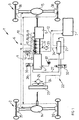
- Figure 1 shows a hydraulic oil and coolant diagram for a temperature regulating system 1 for a vehicle in the form of a wheel loader.
- the wheel loader comprises a rear axle 2, a front axle 3, a diesel engine 4- and a gearbox 5 connected to the engine.
- a transfer gearbox (not shown) for distributing the power to the rear axle and the front axle.
- rear axle or front axle 2, 3 means the whole mechanical construction which transmits the driving power to driving wheels on the right and the left side of the axle.
- the rear axle 2 comprises a rear axle box which encloses a central gear 14, by means of which the driving power is turned through 90°. From the central gear, the driving power is transmitted via driving axles to the driving wheels.
- the central gear comprises a pinion, a drive gear and a differential gear.
- a hub reduction gear in the form of a planetary gear (not shown) is also arranged at each wheel. By means of the hub reduction gear, a reduction of the speed to the driving wheels is brought about.
- the gear wheels forming part of the central gear and the hub reduction gear require lubrication.
- the rear axle box also encloses a brake 35 arranged at the respective wheel.
- the brake is what is known as a wet brake and comprises a set of brake disks enclosed in a housing. The disks are cooled by an oil.
- the temperature regulating system 1 comprises a hydraulic arrangement 6 which is adapted to provide components intended for rotation belonging to the axles 2, 3 of the vehicle with hydraulic oil from a container 7 via a hydraulic oil circuit.
- components intended for rotation means, for example, said gear wheels in the central gear 14, 15 and the hub reduction gear and also the disks in the brakes 35, 36. In other words, the same oil is used for lubricating the gear wheels and cooling the disks.
- pipes for the hydraulic oil are illustrated by broken lines.
- the tasks of the oil are to lubricate bearings and tooth engagement, to create friction in multiple disk clutches and multiple disk brakes and to transfer heat and cold.
- the hydraulic oil used is therefore intended for on the one hand temperature regulation, that is to say heating and cooling, and on the other hand lubrication of rotating components.
- a first part 9 of the hydraulic oil circuit is connected to the rear axle 2, and a second part 10 of the hydraulic oil circuit is connected to the front axle 3.
- the gearbox 5 comprises a number of shafts. Arranged on each of these is a number of gear wheels. The gear wheels are engaged and disengaged depending on the gear selected.
- the hydraulic arrangement 6 is also adapted to provide the gear wheels in the gearbox 5 of the vehicle with hydraulic oil from said container 7. A third part 11 of the hydraulic oil circuit is to this end connected to the gearbox 5.
- the hydraulic oil can also be provided to disks of the clutch means of the gearbox 5.
- the hydraulic arrangement 6 comprises said container 7 for the hydraulic oil and a first pump 8 for suction of the oil via a pipe 12, common to the hydraulic oil circuit parts 9, 10, 11, from the container 7.
- the common pipe 12 divides into the hydraulic oil circuit parts 9, 10, 11 for the gearbox 5 and for the axles 2, 3.
- a flow valve 16 is arranged on the pipe 12 in order to distribute the oil to the axles.
- the hydraulic arrangement 6 also comprises two drainage pumps 17, 18 for pumping the oil supplied to the rear axle 2 and, respectively, the front axle 3 back to the container 7.
- the pipes from the drainage pumps 17, 18 are combined at a point 19.
- the hydraulic arrangement also comprises a drainage pump 20 for pumping the oil supplied to the gearbox 5 back to the container 7.
- a pipe from the drainage pump 20 is combined with the pipes from the drainage pumps 17, 18 of the axles at the point 19.
- a common pipe 34 leads from the point 19 where the pipes are combined to a heat exchanger unit 21.
- a cleaning unit in the form of a filter, or a strainer, 33 is connected on a pipe between the axles 2, 3 and the container 7.
- the filter 33 is arranged on the pipe 34 between the drainage pumps 17, 18, 20 and the heat exchanger unit 21. In the event of damage in one of the axles, undesirable particles will be filtered out and will therefore not find their way into and dirty the hydraulic oil container 7.
- Each of the pumps 8, 17, 18, 20 is adapted to provide a flow which corresponds to the engine speed.
- the pumps 8, 17, 18, 20 are therefore arranged on a crankshaft 13 from the diesel engine 4.
- the temperature regulating system 1 comprises an arrangement 22 for regulating the temperature of the oil in the hydraulic arrangement 6 via the heat exchanger unit 21.
- the temperature regulating arrangement 22 is also adapted to cool the engine 4 of the vehicle.
- the heat exchanger unit 21 is adapted for heat exchange between the oil pumped from the gearbox 5 and the axles 2, 3 and coolant from the diesel engine 4.
- the heat exchanger unit 21 is arranged upstream of the container 7 in the flow direction of the hydraulic oil.
- pipes for the coolant are illustrated by solid lines.
- the temperature regulating arrangement 22 comprises a coolant pump 37 which pumps the coolant in a coolant circuit.
- the coolant is pumped through cooling ducts in the engine block and cylinder head of the engine 4 and, in a first part 26 of the coolant circuit, on to a radiator 23.
- the coolant is pumped from the radiator 23 to the heat exchanger unit 21 and then back to the engine 4.
- a second part 27 of the coolant circuit is connected in parallel with the radiator 23. When the coolant is led through this second part 27, it is therefore not cooled by the radiator 23.
- the temperature regulating arrangement comprises a directional valve 30 for directing the coolant to the coolant circuit parts 26, 27.
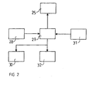
- the temperature regulating system 1 comprises a sensor 28, see figure 2, for sensing the temperature of the oil and a control unit 29 connected to the sensor.
- the control unit 29 is also connected to the directional valve 30 for controlling the position thereof.
- the temperature regulating arrangement is adapted to cool or heat the oil depending on the sensed oil temperature.
- the temperature regulating system also comprises a sensor 31 for sensing the temperature of the coolant of the engine and another directional valve 32 adapted to direct the coolant into a pipe to the heat exchanger unit 21 or past it.
- the sensor 31 and the directional valve 32 are connected to the control unit 29.
- the control unit 29 itself comprises a memory, which includes software segments, for controlling the hydraulic motor 25 and the directional valves 30, 32 depending on the temperatures of the hydraulic oil and the coolant sensed by the sensors 28 and, respectively, 31.
- the hydraulic oil When the vehicle is cold-started, the hydraulic oil is cold.
- the engine coolant is led through the pipe 27 parallel to the radiator 23 to the heat exchanger unit 21 in order to heat the oil.
- a predetermined oil temperature for example 65°C
- the directional valve 30 is switched over so that coolant is led through the radiator 23. This coolant is then cooled down by the radiator.
- the directional valve 32 is set in such a position that the liquid cooled in the radiator 23 is led past the heat exchanger unit 21, that is to say not through it.
- a second predetermined oil temperature for example 87°C
- the directional valve 32 is switched over so that the liquid cooled in the radiator 23 is led through the heat exchanger unit 21.
- the oil will then be cooled.
- the coolant when the hydraulic oil has reached a suitable working temperature, the coolant will instead lead superfluous heat away from the hydraulic oil for the purpose of keeping the hydraulic oil temperature at a suitable level.
- the oil temperature sensor 28 is, for example, arranged in the hydraulic oil container 7.
- the coolant sensor 31 is, for example, arranged in the radiator 23.
- the hydraulic oil container 7 is positioned apart from both the axles 2, 3 and the gearbox 5, and the hydraulic oil is pumped to these parts.
- the rear axle box served as a container for the hydraulic oil.
- the gear wheels in the central gear then rotated in an oil bath.
- the power losses in the form of what are known as drag or splash losses, which arise when components rotate in the oil bath can be reduced.
- the system is of the dry sump type.
- the oil is now sprayed, injected or sprinkled instead onto the components which require lubrication or cooling and the oil is subsequently sucked away from the space concerned, such as the axle box and the gearbox casing.
- the system comprises spraying means, which can consist of a nozzle or another opening connected to the hydraulic oil supply pipe.
- the system also comprises means for removing the oil in said space.
- Such oil removal means consist of one of said pumps.
- the oil removal means are adapted essentially to suck the space dry. This means that no oil or only a small quantity of oil is present in an inactive state in the space, that is to say in the bottom of the space.
- the axle box will not serve as a container for the hydraulic oil, the box can moreover be made smaller, which is cost-effective from the point of view of manufacture.
- the pumps 8, 17, 18, 20 are adapted for pumping in such a manner that hydraulic oil is pumped essentially continuously to and from the gearbox 5 and, respectively, the axles 2, 3.
- the pump 20 for pumping hydraulic oil from the gearbox 5 is adapted to pump oil essentially continuously from a vessel, located in the gearbox, for collecting the oil supplied to the gear wheels of the gearbox.
- the vehicle consists of a transport machine.
- Transport machine means, for example, a loader for transporting materials or objects, such as a truck, a wheel loader, an articulated or frame-steered vehicle (what is known as a dumper), and vehicles for transporting people, such as a bus.
- the brakes 35, 36 are cooled separately.
- the hydraulic oil is not pumped from the temperature regulating system to the wheel brakes.
- the hydraulic arrangement is also adapted to provide the transfer gearbox of the vehicle with hydraulic oil from the container 7.
- the temperature regulating system prefferably has, in addition to said container 7, one or more further containers for the hydraulic oil.
- the same oil is in such a case still used for all the components in the system.
Landscapes
- Engineering & Computer Science (AREA)
- General Engineering & Computer Science (AREA)
- Mechanical Engineering (AREA)
- General Details Of Gearings (AREA)
- Control Of Temperature (AREA)
- Adhesives Or Adhesive Processes (AREA)
Abstract
Description
The
Claims (14)
- A temperature regulating system for a vehicle, the system comprises a container (7) for hydraulic oil and a hydraulic arrangement (6) which is adapted to provide components intended for rotation located in a gearbox (5) of the vehicle and in at least one of the axles (2, 3) of the vehicle with hydraulic oil from the same container (7) characterized in that the hydraulic arrangement (6) comprises at least two pumps (17, 18, 20), namely one (20) for suction of oil from a gearbox space housing said components and one (17, 18) for suction of oil from a vehicle axle space housing said components and that at least one space for housing at least one of said components is adapted for a dry sump.
- The temperature regulating system as claimed in claim 1, characterized in that the hydraulic arrangement (6) comprises means for spraying the hydraulic oil over said components and means (17, 18, 20) for removing the oil from said space.
- The temperature regulating system as claimed in claim 2, characterized in that said oil removal means (17, 18, 20) are adapted to remove the oil continuously from the space during operation of the vehicle in such a manner that no oil or only a small quantity of oil is present in an inactive state in the space.
- The temperature regulating system as claimed in any one of the preceding claims, characterized in that the hydraulic arrangement (6) comprises at least one first pump (8) for pumping oil from the container (7) to the gearbox (5) and to the vehicle axle (2, 3).
- The temperature regulating system as claimed in claim 4, characterized in that each of the second pumps (17, 18, 20) for removing oil from the gearbox (5) and, respectively, the axle (2, 3) has a pump capacity which is at least the same as and preferably greater than that of the first pump (8) for supplying oil connected to the gearbox and to the axle.
- The temperature regulating system as claimed in any one of the preceding claims, characterized in that the container (7) is located apart from the space in which said rotating components forming part of the axle (2, 3) are arranged.
- The temperature regulating system as claimed in any one of the preceding claims, characterized in that the container (7) is located apart from the space in which said rotating components forming part of the gearbox (5) are arranged.
- The temperature regulating system as claimed in any one of the preceding claims, characterized in that said components intended for rotation located in the axles (2, 3) of the vehicle comprise on the one hand disks in a wet brake (35, 36) and on the other hand gear wheels in a gear (14, 15).
- The temperature regulating system as claimed in any one of the preceding claims, characterized in that the temperature regulating system (1) comprises an arrangement (22) for regulating the temperature of the oil in the hydraulic arrangement (6) via a heat exchanger unit (21).
- The temperature regulating system as claimed in claim 9, characterized in that the temperature regulating arrangement (22) is also adapted to cool the engine (4) of the vehicle.
- The temperature regulating system as claimed in claim 9 or 10, characterized in that the temperature regulating arrangement (22) comprises a sensor (28) for sensing the temperature of the oil and a control unit (29) connected to the sensor, and in that the temperature regulating arrangement is adapted to cool or heat the oil depending on the sensed oil temperature.
- The temperature regulating system as claimed in claims 10 and 11, characterized in that the temperature regulating arrangement (22) comprises a sensor (31) connected to the control unit (29) for sensing the temperature of the coolant of the engine.
- Use of the temperature regulating system as claimed in any one of the preceding claims, in a transport machine.
- Use of the temperature regulating system as claimed in any of claims 1-12, in a construction machine.
Applications Claiming Priority (3)
| Application Number | Priority Date | Filing Date | Title |
|---|---|---|---|
| SE0100386A SE523101C2 (en) | 2001-02-07 | 2001-02-07 | temperature regulating |
| SE0100386 | 2001-02-07 | ||
| PCT/SE2002/000010 WO2002062624A1 (en) | 2001-02-07 | 2002-01-04 | A temperature regulating system |
Publications (2)
| Publication Number | Publication Date |
|---|---|
| EP1360091A1 EP1360091A1 (en) | 2003-11-12 |
| EP1360091B1 true EP1360091B1 (en) | 2005-07-27 |
Family
ID=20282882
Family Applications (1)
| Application Number | Title | Priority Date | Filing Date |
|---|---|---|---|
| EP02740062A Expired - Lifetime EP1360091B1 (en) | 2001-02-07 | 2002-01-04 | A temperature regulating system |
Country Status (6)
| Country | Link |
|---|---|
| EP (1) | EP1360091B1 (en) |
| AT (1) | ATE300448T1 (en) |
| BR (1) | BR0206989B1 (en) |
| DE (1) | DE60205217T2 (en) |
| SE (1) | SE523101C2 (en) |
| WO (1) | WO2002062624A1 (en) |
Families Citing this family (3)
| Publication number | Priority date | Publication date | Assignee | Title |
|---|---|---|---|---|
| SE523669C2 (en) * | 2002-09-13 | 2004-05-11 | Volvo Constr Equip Holding Se | Cooling system for a vehicle and vehicle comprising the cooling system |
| DE10300637A1 (en) * | 2003-01-10 | 2004-07-22 | Zf Friedrichshafen Ag | Vehicle axle oiling device for oiling/greasing a motor vehicle's axle has an external oil circuit to maintain a link to axle units and components to be greased/oiled via pipelines and drilled holes |
| SE532421C2 (en) * | 2008-05-23 | 2010-01-19 | Scania Cv Ab | Apparatus and method for controlling the oil temperature of a gearbox and a gearbox |
Family Cites Families (2)
| Publication number | Priority date | Publication date | Assignee | Title |
|---|---|---|---|---|
| DE4140667C2 (en) * | 1991-12-10 | 1994-06-23 | Daimler Benz Ag | Lubricating oil system |
| SE509903C2 (en) * | 1998-02-27 | 1999-03-22 | Volvo Wheel Loaders Ab | Cooling and heating systems |
-
2001
- 2001-02-07 SE SE0100386A patent/SE523101C2/en not_active IP Right Cessation
-
2002
- 2002-01-04 EP EP02740062A patent/EP1360091B1/en not_active Expired - Lifetime
- 2002-01-04 DE DE60205217T patent/DE60205217T2/en not_active Expired - Lifetime
- 2002-01-04 BR BRPI0206989-0A patent/BR0206989B1/en not_active IP Right Cessation
- 2002-01-04 WO PCT/SE2002/000010 patent/WO2002062624A1/en not_active Ceased
- 2002-01-04 AT AT02740062T patent/ATE300448T1/en not_active IP Right Cessation
Also Published As
| Publication number | Publication date |
|---|---|
| EP1360091A1 (en) | 2003-11-12 |
| ATE300448T1 (en) | 2005-08-15 |
| BR0206989B1 (en) | 2011-09-06 |
| SE523101C2 (en) | 2004-03-30 |
| SE0100386D0 (en) | 2001-02-07 |
| BR0206989A (en) | 2004-02-10 |
| DE60205217D1 (en) | 2005-09-01 |
| WO2002062624A1 (en) | 2002-08-15 |
| SE0100386L (en) | 2002-08-08 |
| DE60205217T2 (en) | 2006-05-24 |
Similar Documents
| Publication | Publication Date | Title |
|---|---|---|
| US6899074B1 (en) | Temperature regulating system | |
| US6758266B1 (en) | Work machine having a hydraulic liquid cooling and heating system | |
| US6021868A (en) | Mechanical transmission cooling and lubrication using associated engine systems | |
| CN103419622B (en) | Chiller and cooling means for vehicle drive system | |
| EP1284344B1 (en) | Electronic fan control | |
| KR102305569B1 (en) | External lube system for a transmission | |
| US20130153180A1 (en) | Cooling System With Dual Reversing Fans | |
| US7845471B2 (en) | External axle cooling system | |
| US20090235781A1 (en) | Transfer case arrangement | |
| US20180058570A1 (en) | Lubricating system for a vehicle transmission component, vehicle therewith, and method of lubricating a transmission component | |
| CN101417608A (en) | Regulating transmission fluid and engine coolant temperatures in a motor vehicle | |
| CN102717699A (en) | Combined radiating system, vehicle chassis and engineering vehicle | |
| EP3267007B1 (en) | Utility vehicle fluid cooling | |
| CN116615349A (en) | Drive train of work machine, method for operating drive train, and work machine | |
| US6135065A (en) | Cooling system for a machine | |
| EP1360091A1 (en) | A temperature regulating system | |
| US7281619B2 (en) | Multiple-disk brake or clutch | |
| EP1954519B1 (en) | Power generation arrangement | |
| JP2005539169A (en) | Cooling device for vehicle and vehicle including the cooling device | |
| CN114056109A (en) | A method for improving automobile low temperature transmission efficiency and automobile electric drive system | |
| US20100236235A1 (en) | Hydraulic fluid cooling system for pair of integrated hydrostatic transmissions | |
| JP4285819B2 (en) | Mechanical cooling system | |
| CN220956747U (en) | Driving axle heat dissipation control system and operation machine | |
| CN121291346A (en) | A graded cooling system for axles, a graded cooling assembly for axles, and an engineering vehicle. | |
| JPS6233157Y2 (en) |
Legal Events
| Date | Code | Title | Description |
|---|---|---|---|
| PUAI | Public reference made under article 153(3) epc to a published international application that has entered the european phase |
Free format text: ORIGINAL CODE: 0009012 |
|
| 17P | Request for examination filed |
Effective date: 20030908 |
|
| AK | Designated contracting states |
Kind code of ref document: A1 Designated state(s): AT BE CH CY DE DK ES FI FR GB GR IE IT LI LU MC NL PT SE TR |
|
| AX | Request for extension of the european patent |
Extension state: AL LT LV MK RO SI |
|
| 17Q | First examination report despatched |
Effective date: 20040727 |
|
| GRAP | Despatch of communication of intention to grant a patent |
Free format text: ORIGINAL CODE: EPIDOSNIGR1 |
|
| GRAS | Grant fee paid |
Free format text: ORIGINAL CODE: EPIDOSNIGR3 |
|
| GRAA | (expected) grant |
Free format text: ORIGINAL CODE: 0009210 |
|
| AK | Designated contracting states |
Kind code of ref document: B1 Designated state(s): AT BE CH CY DE DK ES FI FR GB GR IE IT LI LU MC NL PT SE TR |
|
| PG25 | Lapsed in a contracting state [announced via postgrant information from national office to epo] |
Ref country code: IT Free format text: LAPSE BECAUSE OF FAILURE TO SUBMIT A TRANSLATION OF THE DESCRIPTION OR TO PAY THE FEE WITHIN THE PRESCRIBED TIME-LIMIT;WARNING: LAPSES OF ITALIAN PATENTS WITH EFFECTIVE DATE BEFORE 2007 MAY HAVE OCCURRED AT ANY TIME BEFORE 2007. THE CORRECT EFFECTIVE DATE MAY BE DIFFERENT FROM THE ONE RECORDED. Effective date: 20050727 Ref country code: BE Free format text: LAPSE BECAUSE OF FAILURE TO SUBMIT A TRANSLATION OF THE DESCRIPTION OR TO PAY THE FEE WITHIN THE PRESCRIBED TIME-LIMIT Effective date: 20050727 Ref country code: TR Free format text: LAPSE BECAUSE OF FAILURE TO SUBMIT A TRANSLATION OF THE DESCRIPTION OR TO PAY THE FEE WITHIN THE PRESCRIBED TIME-LIMIT Effective date: 20050727 Ref country code: NL Free format text: LAPSE BECAUSE OF FAILURE TO SUBMIT A TRANSLATION OF THE DESCRIPTION OR TO PAY THE FEE WITHIN THE PRESCRIBED TIME-LIMIT Effective date: 20050727 Ref country code: AT Free format text: LAPSE BECAUSE OF FAILURE TO SUBMIT A TRANSLATION OF THE DESCRIPTION OR TO PAY THE FEE WITHIN THE PRESCRIBED TIME-LIMIT Effective date: 20050727 Ref country code: FI Free format text: LAPSE BECAUSE OF FAILURE TO SUBMIT A TRANSLATION OF THE DESCRIPTION OR TO PAY THE FEE WITHIN THE PRESCRIBED TIME-LIMIT Effective date: 20050727 Ref country code: CH Free format text: LAPSE BECAUSE OF FAILURE TO SUBMIT A TRANSLATION OF THE DESCRIPTION OR TO PAY THE FEE WITHIN THE PRESCRIBED TIME-LIMIT Effective date: 20050727 Ref country code: LI Free format text: LAPSE BECAUSE OF FAILURE TO SUBMIT A TRANSLATION OF THE DESCRIPTION OR TO PAY THE FEE WITHIN THE PRESCRIBED TIME-LIMIT Effective date: 20050727 |
|
| REG | Reference to a national code |
Ref country code: GB Ref legal event code: FG4D |
|
| REG | Reference to a national code |
Ref country code: CH Ref legal event code: EP |
|
| REG | Reference to a national code |
Ref country code: IE Ref legal event code: FG4D |
|
| REF | Corresponds to: |
Ref document number: 60205217 Country of ref document: DE Date of ref document: 20050901 Kind code of ref document: P |
|
| PG25 | Lapsed in a contracting state [announced via postgrant information from national office to epo] |
Ref country code: SE Free format text: LAPSE BECAUSE OF FAILURE TO SUBMIT A TRANSLATION OF THE DESCRIPTION OR TO PAY THE FEE WITHIN THE PRESCRIBED TIME-LIMIT Effective date: 20051027 Ref country code: GR Free format text: LAPSE BECAUSE OF FAILURE TO SUBMIT A TRANSLATION OF THE DESCRIPTION OR TO PAY THE FEE WITHIN THE PRESCRIBED TIME-LIMIT Effective date: 20051027 Ref country code: DK Free format text: LAPSE BECAUSE OF FAILURE TO SUBMIT A TRANSLATION OF THE DESCRIPTION OR TO PAY THE FEE WITHIN THE PRESCRIBED TIME-LIMIT Effective date: 20051027 |
|
| PG25 | Lapsed in a contracting state [announced via postgrant information from national office to epo] |
Ref country code: PT Free format text: LAPSE BECAUSE OF FAILURE TO SUBMIT A TRANSLATION OF THE DESCRIPTION OR TO PAY THE FEE WITHIN THE PRESCRIBED TIME-LIMIT Effective date: 20051227 |
|
| PG25 | Lapsed in a contracting state [announced via postgrant information from national office to epo] |
Ref country code: GB Free format text: LAPSE BECAUSE OF NON-PAYMENT OF DUE FEES Effective date: 20060104 Ref country code: IE Free format text: LAPSE BECAUSE OF NON-PAYMENT OF DUE FEES Effective date: 20060104 |
|
| PG25 | Lapsed in a contracting state [announced via postgrant information from national office to epo] |
Ref country code: MC Free format text: LAPSE BECAUSE OF NON-PAYMENT OF DUE FEES Effective date: 20060131 Ref country code: LU Free format text: LAPSE BECAUSE OF NON-PAYMENT OF DUE FEES Effective date: 20060131 |
|
| REG | Reference to a national code |
Ref country code: CH Ref legal event code: PL |
|
| NLV1 | Nl: lapsed or annulled due to failure to fulfill the requirements of art. 29p and 29m of the patents act | ||
| PLBE | No opposition filed within time limit |
Free format text: ORIGINAL CODE: 0009261 |
|
| STAA | Information on the status of an ep patent application or granted ep patent |
Free format text: STATUS: NO OPPOSITION FILED WITHIN TIME LIMIT |
|
| 26N | No opposition filed |
Effective date: 20060428 |
|
| EN | Fr: translation not filed | ||
| PG25 | Lapsed in a contracting state [announced via postgrant information from national office to epo] |
Ref country code: FR Free format text: LAPSE BECAUSE OF FAILURE TO SUBMIT A TRANSLATION OF THE DESCRIPTION OR TO PAY THE FEE WITHIN THE PRESCRIBED TIME-LIMIT Effective date: 20060922 |
|
| GBPC | Gb: european patent ceased through non-payment of renewal fee |
Effective date: 20060104 |
|
| REG | Reference to a national code |
Ref country code: IE Ref legal event code: MM4A |
|
| PG25 | Lapsed in a contracting state [announced via postgrant information from national office to epo] |
Ref country code: FR Free format text: LAPSE BECAUSE OF FAILURE TO SUBMIT A TRANSLATION OF THE DESCRIPTION OR TO PAY THE FEE WITHIN THE PRESCRIBED TIME-LIMIT Effective date: 20050727 Ref country code: CY Free format text: LAPSE BECAUSE OF FAILURE TO SUBMIT A TRANSLATION OF THE DESCRIPTION OR TO PAY THE FEE WITHIN THE PRESCRIBED TIME-LIMIT Effective date: 20050727 |
|
| PG25 | Lapsed in a contracting state [announced via postgrant information from national office to epo] |
Ref country code: ES Free format text: LAPSE BECAUSE OF NON-PAYMENT OF DUE FEES Effective date: 20060131 |
|
| PGFP | Annual fee paid to national office [announced via postgrant information from national office to epo] |
Ref country code: DE Payment date: 20130103 Year of fee payment: 12 |
|
| REG | Reference to a national code |
Ref country code: DE Ref legal event code: R119 Ref document number: 60205217 Country of ref document: DE |
|
| PG25 | Lapsed in a contracting state [announced via postgrant information from national office to epo] |
Ref country code: DE Free format text: LAPSE BECAUSE OF NON-PAYMENT OF DUE FEES Effective date: 20140801 |
|
| REG | Reference to a national code |
Ref country code: DE Ref legal event code: R119 Ref document number: 60205217 Country of ref document: DE Effective date: 20140801 |