EP1360061B1 - Device for producing plastic pipes - Google Patents
Device for producing plastic pipes Download PDFInfo
- Publication number
- EP1360061B1 EP1360061B1 EP02712769A EP02712769A EP1360061B1 EP 1360061 B1 EP1360061 B1 EP 1360061B1 EP 02712769 A EP02712769 A EP 02712769A EP 02712769 A EP02712769 A EP 02712769A EP 1360061 B1 EP1360061 B1 EP 1360061B1
- Authority
- EP
- European Patent Office
- Prior art keywords
- distribution
- branch
- passage
- radial
- passage portions
- Prior art date
- Legal status (The legal status is an assumption and is not a legal conclusion. Google has not performed a legal analysis and makes no representation as to the accuracy of the status listed.)
- Expired - Lifetime
Links
Images


Classifications
-
- B—PERFORMING OPERATIONS; TRANSPORTING
- B29—WORKING OF PLASTICS; WORKING OF SUBSTANCES IN A PLASTIC STATE IN GENERAL
- B29C—SHAPING OR JOINING OF PLASTICS; SHAPING OF MATERIAL IN A PLASTIC STATE, NOT OTHERWISE PROVIDED FOR; AFTER-TREATMENT OF THE SHAPED PRODUCTS, e.g. REPAIRING
- B29C48/00—Extrusion moulding, i.e. expressing the moulding material through a die or nozzle which imparts the desired form; Apparatus therefor
- B29C48/25—Component parts, details or accessories; Auxiliary operations
- B29C48/36—Means for plasticising or homogenising the moulding material or forcing it through the nozzle or die
- B29C48/50—Details of extruders
- B29C48/695—Flow dividers, e.g. breaker plates
- B29C48/70—Flow dividers, e.g. breaker plates comprising means for dividing, distributing and recombining melt flows
- B29C48/705—Flow dividers, e.g. breaker plates comprising means for dividing, distributing and recombining melt flows in the die zone, e.g. to create flow homogeneity
-
- B—PERFORMING OPERATIONS; TRANSPORTING
- B29—WORKING OF PLASTICS; WORKING OF SUBSTANCES IN A PLASTIC STATE IN GENERAL
- B29C—SHAPING OR JOINING OF PLASTICS; SHAPING OF MATERIAL IN A PLASTIC STATE, NOT OTHERWISE PROVIDED FOR; AFTER-TREATMENT OF THE SHAPED PRODUCTS, e.g. REPAIRING
- B29C48/00—Extrusion moulding, i.e. expressing the moulding material through a die or nozzle which imparts the desired form; Apparatus therefor
- B29C48/001—Combinations of extrusion moulding with other shaping operations
- B29C48/0013—Extrusion moulding in several steps, i.e. components merging outside the die
- B29C48/0015—Extrusion moulding in several steps, i.e. components merging outside the die producing hollow articles having components brought in contact outside the extrusion die
-
- B—PERFORMING OPERATIONS; TRANSPORTING
- B29—WORKING OF PLASTICS; WORKING OF SUBSTANCES IN A PLASTIC STATE IN GENERAL
- B29C—SHAPING OR JOINING OF PLASTICS; SHAPING OF MATERIAL IN A PLASTIC STATE, NOT OTHERWISE PROVIDED FOR; AFTER-TREATMENT OF THE SHAPED PRODUCTS, e.g. REPAIRING
- B29C48/00—Extrusion moulding, i.e. expressing the moulding material through a die or nozzle which imparts the desired form; Apparatus therefor
- B29C48/03—Extrusion moulding, i.e. expressing the moulding material through a die or nozzle which imparts the desired form; Apparatus therefor characterised by the shape of the extruded material at extrusion
- B29C48/09—Articles with cross-sections having partially or fully enclosed cavities, e.g. pipes or channels
-
- B—PERFORMING OPERATIONS; TRANSPORTING
- B29—WORKING OF PLASTICS; WORKING OF SUBSTANCES IN A PLASTIC STATE IN GENERAL
- B29C—SHAPING OR JOINING OF PLASTICS; SHAPING OF MATERIAL IN A PLASTIC STATE, NOT OTHERWISE PROVIDED FOR; AFTER-TREATMENT OF THE SHAPED PRODUCTS, e.g. REPAIRING
- B29C48/00—Extrusion moulding, i.e. expressing the moulding material through a die or nozzle which imparts the desired form; Apparatus therefor
- B29C48/16—Articles comprising two or more components, e.g. co-extruded layers
- B29C48/18—Articles comprising two or more components, e.g. co-extruded layers the components being layers
- B29C48/21—Articles comprising two or more components, e.g. co-extruded layers the components being layers the layers being joined at their surfaces
-
- B—PERFORMING OPERATIONS; TRANSPORTING
- B29—WORKING OF PLASTICS; WORKING OF SUBSTANCES IN A PLASTIC STATE IN GENERAL
- B29C—SHAPING OR JOINING OF PLASTICS; SHAPING OF MATERIAL IN A PLASTIC STATE, NOT OTHERWISE PROVIDED FOR; AFTER-TREATMENT OF THE SHAPED PRODUCTS, e.g. REPAIRING
- B29C48/00—Extrusion moulding, i.e. expressing the moulding material through a die or nozzle which imparts the desired form; Apparatus therefor
- B29C48/25—Component parts, details or accessories; Auxiliary operations
- B29C48/30—Extrusion nozzles or dies
- B29C48/303—Extrusion nozzles or dies using dies or die parts movable in a closed circuit, e.g. mounted on movable endless support
-
- B—PERFORMING OPERATIONS; TRANSPORTING
- B29—WORKING OF PLASTICS; WORKING OF SUBSTANCES IN A PLASTIC STATE IN GENERAL
- B29C—SHAPING OR JOINING OF PLASTICS; SHAPING OF MATERIAL IN A PLASTIC STATE, NOT OTHERWISE PROVIDED FOR; AFTER-TREATMENT OF THE SHAPED PRODUCTS, e.g. REPAIRING
- B29C49/00—Blow-moulding, i.e. blowing a preform or parison to a desired shape within a mould; Apparatus therefor
- B29C49/0015—Making articles of indefinite length, e.g. corrugated tubes
- B29C49/0021—Making articles of indefinite length, e.g. corrugated tubes using moulds or mould parts movable in a closed path, e.g. mounted on movable endless supports
Definitions
- Such devices with a spray head with a distributor with perpendicular to the axis of the mold cavity extending distribution channels have the Advantage that the spray head on the one hand with a short overall length and on the other hand with small diameter can be formed, so that the distribution device, preferably formed as a plate, within the cross section of the mold cavity can be arranged. Due to the small spray head length, the Feed channel for the melt over much of its length with a relatively large Diameter be formed so that with comparatively low pressures can be worked, but still sufficient melt the annular gap or fed to the production direction one behind the other connected annular gaps.
- a device of the type mentioned with spray head is known from US 3,809,515 known.
- the spray head is not designed as a plate spray head, he points However, already perpendicular to the central axis extending distribution channels.
- the Distributing channels are directed radially with arcuate end portions, in the manner of a Open spiral distributor in the outer annular gap.
- the variability of the Degree of distribution is on the one hand by the radial orientation of the channels and on the other hand, by the design of the adjoining spiral distributor limited.
- a significant limitation arises from the fact that after Concept of US 3,809,515 the flow paths in the distribution channels be exactly the same length need to ensure a homogeneous volume flow.
- a device is formed as a plate Known spray head.
- the distribution channels of this so-called Plattenspritzkopfs are as pedigree branched channels formed. To form these channels are in a distribution plate corresponding grooves formed over a cover plate are covered.
- Disadvantage due to the tree branched distribution channels is that the variability of the number of distribution channels or the variability of the Branching degree of the distribution channels on stages forming powers of 2, is limited and therefore a continuous variation is not possible.
- Another fundamental constructive limitation results from the fact that the distribution channels be formed according to the concept of DE 198 35 189 each exactly the same length in order to ensure equal flow paths, eventually to a homogeneous Composition of emerging at the annular gap plastic strand guarantee.
- the disk spray head has a distribution plate with substantially star-shaped radial grooves, which are covered by a cover plate form radial radial distribution channels.
- the plastic melt is a to Central axis of the mold cavity concentric annular gap of this distribution plate fed.
- the melt is the outer Circumference of the distribution plate arranged annular gap with integrated therein Spiral distributor supplied.
- the in DE 27 52 932 illustrated embodiment provided that the from inner annular gap emanating star-shaped distribution channels in an annular Distribution channel open, from which further radial distribution channels increased number radiate out.
- the invention is based on the object, a device of the aforementioned Type so on form that a homogeneous composition of the am Annular gaps of the spray head exiting plastic melt jet is obtained.
- each flow path of the Inlet into the manifold to the junction of the distribution channels in the Annular gap extends.
- a branched channel results in one of the number of Branch channels corresponding number n of flow paths.
- the flow resistance in the for the individual flow paths through distribution channels i. the flow resistance the successively flowed through the channel sections of the respective distribution channels different flow paths is designed according to different.
- the inner diameter of the case The various flow paths through channel sections depending on the Length of the respective flow path are designed differently.
- Each distribution channel may have one or more branch points, from each run two or more branch channels.
- the Distribution channels in terms of their degree of branching and in terms of the length of the Channel sections are formed differently and the individual flow paths from the inlet to the mouth in the annular gap can have different length.
- the individual channel sections can be any Curve shape, but are preferably for manufacturing reasons as straight Channel sections formed.
- the end portions of the Distribution channels before their confluence in the annular gap in arcuate preferably pass over arcuate channel sections, in the manner of a Spiral distributor can be arranged and the plastic melt in the Initiate annular gap.
- the inlet opening into the manifold is coaxial to the axis of the mold cavity or to the axis of the preferably annular annular gap.
- the inlet opening in the distribution device can However, also be arranged off-center and there may be several Inlets, preferably in a common plane in the Distributor be arranged.
- the solution according to claim 3 also sees a plurality of Distribution channels, each in at least one branch point under Branch each branching two branch channel sections.
- the order the distribution channels is star-shaped from the central inlet opening in the Distributor. It is essential that the radially from the inlet opening outgoing first channel sections of the distribution channels each straight are and these straight radial first channel sections at their end respectively have a branching point in which they are in at least two Branching branch channel sections.
- the arrangement is so far symmetrical star-shaped starting from the inlet opening. If necessary, the distribution channels will follow repeated further branching finally in arcuate, preferably circular arc-shaped end portions over, in the manner of a spiral distributor the Apply plastic melt to the annular gap.
- Branching points in the star-shaped distribution channels on a concentric line around the inlet opening are arranged and in the branching points a Branching occurs in more than two branch channels, resulting in the flow paths by the branch channels of a distribution channel different length, at Versions in which the branch channels on a concentric line in to Ring gap leading equal length end sections open. This is the case when the Branch channels directly into the arcuate channel sections of the Turn over spiral distributor.
- a balance of these different lengths Flow paths can be done in special versions in that the subsequent channel sections to compensate for each corresponding have longer or shorter flow path. In this way can be achieved be that the entire flow path of the adjoining channel sections between the inlet opening and the junction in the annular gap in each case the same is long.
- the compensation of the Flow paths of different lengths take place in that in the channel sections, which are flowed through in the course of the various flow paths, the Flow resistance is designed differently according to, so that Finally, despite different lengths of flow paths in each case in the confluence in the annular gap of the same volume flow is supplied to the annular gap.
- the channel sections are preferably as straight channel sections formed and symmetrical to the axis of the radial arranged first channel section.
- the middle one is three Branch channel sections in a straight line aligned with the radial first Channel section arranged. Due to the straight training of the Channel sections and the branch in a plurality of Branch channel sections results in a high degree of distribution. this applies especially for embodiments in which all of the inlet opening Outgoing distribution channels are designed in this same way and insofar as a symmetry, preferably star structure, is present.
- the distribution device has a distribution plate in which the radial first channel sections as preferably parallel to the plane of the plate extending bores are formed.
- the branch channel sections can be formed as running parallel to the plane of the plate holes. This means that the distribution channels in these sections each by parallel to Plate level extending bores are formed.
- the Holes may also be formed as grooves, which by one or more Overlying cover plates are formed to corresponding channels.
- the distribution device may have a first Distribution plate and have a further distribution plate, wherein in this further Distribution plate sections of the distribution channels, preferably the arcuate channel sections are arranged.
- This further distribution plate can in structurally particularly simple designs as an annular distribution plate be educated.
- the inlet opening and the radial first Channel sections and preferably also the branch channel sections can in one central distribution plate arranged by the annular distribution plate is arranged surrounded.
- a particularly compact arrangement results when the central distribution plate and / or the annular distribution plate a concentric Gradation and have and the two plates complementary are arranged one above the other in terms of gradation.
- the outer annular step edge of the central plate may be the outside overlap annular annular distribution plate and rest on this.
- the arcuate channel sections may be in the outer annular distribution disc arcuate grooves to be formed by the annular step edge of the central plate are covered, so that the arcuate channel sections are formed.
- Particularly compact versions with spray heads with several in Production direction one behind the other arranged distribution devices is in the obtained central arrangement of the inlet opening in the distributor, when the Distributor obtained when the distributor off-center a passage for a supply channel for plastic melt one in the production direction Having downstream distribution device.
- the Distributor also off-center a passage for Supply facilities, e.g. Line for air, electricity, coolant, etc. have.
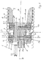
- Fig. 1 is schematically at 1, the corresponding corrugated inner wall of a Corrugator mold baking shown, wherein in the production direction 2 of the corrugated pipe several corresponding mold jaws follow each other directly.
- the Contact surface of two mold jaws is indicated by the line 3 in Fig. 1.
- the production of the multi-walled corrugated pipe is carried out in a conventional manner such that a first, from an annular gap 4 exiting, tubular stream. 5 of plastic melt by suitable means, e.g. in the room 6 applied overpressure, against the inner wall 1 of the corresponding, in Production direction 2 uniformly moving mold baking is created.
- suitable means e.g. in the room 6 applied overpressure
- On the annular gap 4 follows in the production direction 2 then another annular gap 7, from which also emerges a tubular stream 8 of a plastic melt.
- This Plastic melt tube is covered by a dome 9, whose exact training depending on the plastic used and the special pipe shape etc.
- Fig. 1 it can be seen that for this purpose, two total of 13a and 13b designated distribution device are provided. These two distribution devices are basically the same. However, the diameter of the Ring slot 4 for the outer wall 11 in the illustrated embodiment something larger than the diameter of the annular slot 7 for the inner wall 12 and Corresponding are also the diameters of the distributing devices 13a and 13b something different. This is necessary in order to prevent the already on the inner wall 1 of the mold jaws adjacent outer wall 11 of the Plastic corrugated pipe with the distributor 13b comes into contact.
- Each of the distributors 13a and 13b comprises two plate-shaped, in outer plan each circular elements, namely a disc-shaped first plate 15 serving as portions of distribution channels 14 within the Plate 15 has bores formed parallel to the plate plane, and a in plan view annular second plate 16, the groove-shaped recesses has, which rest on the in the region of the groove-shaped recesses disc-shaped plate 15 are covered and thus to the in the plate 15th connect trained holes and so the distribution channels 14th to complete.
- the circular in plan outline peripheral surface 24 of the first plate 15 is at a small distance and forming an annular gap 25 of a Outer ring 26 surrounded, the cross section of Fig. 1 can be seen.
- the two distribution devices 13a, 13b are thus from the plate or annular elements 15, 16, 26 assembled and each have Overall, a flat basically plate-shaped configuration.
- the feeding of the plastic melt from the extruder to the distribution devices 13a, 13b takes place via essentially in the production direction 2 extending Feed channels 17a, 17b, in the central axis 18 of the Korrugatorformbacken formed mold cavity run and comparatively can have large cross-section.
- These supply channels 17a, 17b end each in an inlet opening 20 of the corresponding distributor 13a, 13b, from then the distribution channels (see Fig. 2) go out.
- the second supply channel 17b passes through the first Distributor 13a off-center in the form of a plate 15 formed in the Bore 21.
- the bore 21 passes through the plate 15 off-center with distance Inlet opening 20, however, is arranged in the central region of the plate 15 is not covered by the annular plate 16.
- the bore 21 is thus in the cross-sectional area of the central recess of this annular plate 16 arranged. Therefore, the training of a separate aligned is unnecessary Bore in this annular plate 16th
- Feed channel 17b extends in the spacer block 19 which is between the Distributor 13a and downstream in the production direction Distributor 13b is arranged.
- the feed channel 17b points in its course through the spacer block 19 a to the central axis obliquely directed portion and finally opens into an arranged in the central axis 18 end portion into the central inlet 20 of the distributor 13b.
- the passage 22 is in the appropriate position as the Bore 21 off-center with distance to the inlet opening 20 in the distribution plate 15th and arranged in alignment in each distribution device 13a, 13b, so that the Supply lines parallel offset offset to the central center axis 18 Weden can.
- the passage 22 is in each case in a bore in the plate 15 at a distance arranged to the inlet opening 20. She passes through the plate 15 in a Center near area, so that the passage 22 each in the cross-sectional area the central recess of the annular plate 16 is arranged and a separate bore in the annular plate 16 is unnecessary.
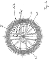
- Fig. 2 is an example of how the distribution channels 14 in the distribution device 13a can be arranged, shown schematically.
- the distribution channels 14 are in the distribution device 13a in a basically arranged star-shaped configuration. All distribution channels 14 have theirs Originating in the central opening 20 and extending in a direction perpendicular to Central axis 18 lying plane A to the periphery of the distribution device 13a out to finally einunden in the annular gap 25.
- the annular gap 25 is between the Peripheral surface 24 of the plate 15 and the radial inner side of the outer ring 26th formed and passes directly into the subsequent nozzle, at the Outlet end of the annular gap 4 is formed.
- Each distribution channel 14 consists of a first radially directed straight Channel section 14r extending from the inlet opening 20 to a Branch point 14v extends.
- Branching point 14v branches the radial channel section 14r into three also straight branch channel sections 14z, which then each pass into arcuate channel sections 14k, the art arranged in the plane
- a distributor helix arranged side by side are and in each case on the peripheral surface 24 of the plate 15 terminate by being there in open the annular gap 25.
- each radial channel section 14r intended. They are arranged crosswise to each other, with adjacent ones Channel sections 14r are each arranged at an angle of 90 °.
- the Branching points 14v are all on one to the inlet opening 20th concentric circle. This means that the radial channel sections 14r each are the same length.
- each radial channel section 14r goes in the Branch point 14v in each case three straight branch channel sections 14z over. she each end on a concentric to the inlet 20 circular line by go there in the arcuate channel sections 14 K.
- the middle Branch passage section 14z radially directed in alignment with the radial Channel section 14r.
- the two outer channel sections 14z run on both sides of the central branch channel portion 14z each at an angle of 45 ° directed to this.
- the middle branch passage portion 14z is shorter than each of them two outer branch channel sections 14z.
- the ends of the branch channel sections 14z are each arranged on the concentric circle whose center in the Axis of the inlet opening 20 and thus offset from the branch point 14v is located.
- the two outer channel sections 14z are each the same length due to the the radially directed central branch channel section symmetrical arrangement.
- the diameter of the shorter middle Branch channel portion 14 z each formed smaller than the diameter of the two longer outer channel sections 14z. The relative diameters are so chosen that the different length and the associated different flow path of the branch channel sections 14z is compensated and thus from each branch channel section into the arcuate channel sections 14k in each case the same volume flow is supplied.
- a corresponding different Constriction or extension in the branch channel sections 14z to Compensation of the different lengths of the channel sections may be provided.
- the branch channel sections 14z are not formed identically rectilinear or preferably, that the two outer branch channel sections 14z rectilinear, but the middle Branch channel section 14z is formed odd-lined.
- the Compensation and the arcuate channel sections 14k corresponding Constrictions or extensions or with different Extensions or shortenings may be formed.
- the diameter of all Radial channel sections 14r each identical and over the entire length of the Channel section 14r towards constant.
- the rectilinear adjoining middle of the two channel sections 14z each have the same diameter as the Channel portion 14r, wherein the diameter of this branch channel portion 14z is also constant over the entire length.
- the diameter of the two lateral longer channel sections 14z is each larger than the diameter the middle channel section 14z and also over the entire length of the lateral branch channel sections 14z constant.
- the to the branch channel sections 14z subsequent arcuate channel sections 14k are interconnected identically formed. Their non-circular cross-sectional area corresponds in terms of Area of the cross-sectional area of the side branch passage portions 14z.
- the area of the cross-sectional area of these arcuate channel sections 14k takes, as can be seen from Fig. 1, to the confluence in the annular gap 25 out from.
- the Diameter of the radial channel sections and / or the diameter of Branch channel sections 14z over the length of the respective channel section to Annular gap 25 decreases. The decrease can be continuous over the length of the be formed respective channel sections.
- the arcuate channel sections 14k formed by that in the annular Plate 16 on the support surface with the plate 15 side facing arcuate grooves are formed and these grooves by in this Area resting plate surface of the first distribution plate 15 are covered.
- the arcuate grooves are arranged in the annular plate 16 so that when the Plates are joined, the ends, i. the outlets in the first plate formed branch channel sections 14z respectively open therein.
- the plate 15 is for this purpose as a step plate with a central portion and a formed outer ring stage, wherein the ends of the branch channel sections in the Peripheral surface of the central portion open.
- the complementary graded outer annular plate 16 has an inner annular step and an outer Ring section, wherein the arcuate channel sections 14k forming Grooves are formed in the outer ring portion.
- step plate 15 and ring plate 16 are the arcuate Channel sections formed by support of the outer annular step of the plate 15th on for grooves of the outer ring portion of the plate 16.
- Die Branch channel sections 14z open in each case in the arcuate Channel sections 14k, so continue each of the distribution channels in this way.
- 14 Branch channel sections 14z and 14 arcuate channel sections 14k provided
- Distribution devices corresponding to distribution devices 13a or 13b of the embodiment shown can also be used if only one single-layer pipe to be produced. In this case, then just one only distribution device required. Furthermore, the distribution devices of course also be used when pipes of other types, For example, smooth, seamless tubes to be produced. In this case is It is also not absolutely necessary to provide migratory mold jaws. Here could possibly be with stationary outer shape and a corresponding Kem or Dom are worked.
- Figs. 3 to 5 arrangements are schematically shown as using of the inventive idea, i. using the special ones Distribution devices, devices for the production of corrugated pipes constructed can be.
- FIGS. 3 to 5 a movable, from circulating, is on the right Molded halves 27 formed mold 28 shown.
- this movable form 28 are - according to the embodiment of FIG. 1 - two Distributing devices 13a, 13b arranged via supply channels 17a, 17b be fed.
- the inner and outer walls of the Multi-layered corrugated pipe made of different plastics. Accordingly, two extruders, namely an extruder 29a, which are the Plastic melt for the outer wall 11 supplies, as well as an extruder 29 b for Production of the plastic melt for the inner wall 12 is provided.
- Figs. 4 and 5 are also produced two-walled corrugated pipes.
- the inner and outer walls should be made consist of the same material, which is why only one extruder 29 is provided.
- a conventional distribution box 30th is provided, which over comparatively long supply channels 17a, 17b with the Distributor 13 a, 13 b is connected, the distribution of the out of the Extruder 29 exiting plastic flow in the embodiment of the 5 via a Y-distributor 31, to which directly the supply channels 17a, 17b.
- a Y-distributor 31 to which directly the supply channels 17a, 17b.
- the device described offers a variety of ways that Properties of pipes produced with the device as a function of to influence the plastic used.
Abstract
Description
Die Erfindung betrifft eine Vorrichtung zur Herstellung von nahtlosen
Kunststoffrohren;
mit mindestens einer Extrusionseinrichtung;
mit mindestens einem der Extrusionsrichtung in Produktionsrichtung
nachgeschaltetem Spritzkopf mit mindestens einem Ringspalt;
mit mindestens einem dem Spritzkopf in Produktionsrichtung nachgeschaltetem
Formhohlraum zur Ausformung des Kunststoffrohrs aus mindestens einem aus dem
Ringspalt des Spritzkopfs austretendem Kunststoffschmelzestrom;
wobei vorgesehen ist:
wobei jeder Verteilkanal einen radialen Kanalabschnitt, der von der Eintrittsstelle ausgeht, aufweist;
wobei die insgesamt n Enden der Verteilkanäle im Bereich des Umfangs der Verteileinrichtung in den Ringspalt mit jeweils gleichem Winkelabstand benachbarter Enden unter einem Winkel von 360°/n einmünden unter Ausbildung von n Fließwegen, die sich jeweils ausgehend von der Eintrittsöffnung in einander anschließenden Kanalabschnitten der Verteilkanäle zur Einmündung in den Ringspalt erstrecken und jeweils gleich großen Volumenstrom in den Ringspalt einleiten.The invention relates to a device for producing seamless plastic pipes;
with at least one extrusion device;
with at least one of the extrusion direction downstream in the direction of production spray head with at least one annular gap;
with at least one mold cavity downstream of the spray head in the production direction for shaping the plastic pipe from at least one plastic melt stream emerging from the annular gap of the spray head;
where provided is:
each distribution channel having a radial channel portion extending from the point of entry;
wherein the total n ends of the distribution channels in the region of the circumference of the distributor in the annular gap with the same angular distance of adjacent ends at an angle of 360 ° / n open with the formation of n flow paths, each starting from the inlet opening in subsequent channel sections of the distribution channels extend to the confluence into the annular gap and each introduce the same volume flow in the annular gap.
Derartige Vorrichtungen mit einem Spritzkopf mit einer Verteileinrichtung mit senkrecht zur Achse des Formhohlraums verlaufenden Verteilkanälen haben den Vorteil, daß der Spritzkopf einerseits mit kurzer Baulänge und andererseits auch mit geringem Durchmesser ausgebildet werden kann, so daß die Verteileinrichtung, vorzugsweise als Platte ausgebildet, innerhalb des Querschnitts des Formhohlraums angeordnet werden kann. Aufgrund der geringen Spritzkopfbaulänge kann der Zuführkanal für die Schmelze über einen Großteil seiner Länge mit relativ großem Durchmesser ausgebildet sein, so daß mit vergleichsweise niedrigen Drücken gearbeitet werden kann, trotzdem aber ausreichend Schmelze dem Ringspalt bzw. den in Produktionsrichtung hintereinander geschalteten Ringspalten zugeführt wird.Such devices with a spray head with a distributor with perpendicular to the axis of the mold cavity extending distribution channels have the Advantage that the spray head on the one hand with a short overall length and on the other hand with small diameter can be formed, so that the distribution device, preferably formed as a plate, within the cross section of the mold cavity can be arranged. Due to the small spray head length, the Feed channel for the melt over much of its length with a relatively large Diameter be formed so that with comparatively low pressures can be worked, but still sufficient melt the annular gap or fed to the production direction one behind the other connected annular gaps.
Eine Vorrichtung der eingangs genannten Art mit Spritzkopf ist aus der US 3 809 515 bekannt. Der Spritzkopf ist zwar nicht als Plattenspritzkopf ausgebildet, er weist jedoch bereits senkrecht zur Mittelachse verlaufende Verteilkanäle auf. Die Verteilkanäle sind radial gerichtet mit bogenförmigen Endabschnitten, die in Art eines Wendelverteilers in den äußeren Ringspalt einmünden. Die Variierbarkeit des Verteilungsgrads ist einerseits durch die radiale Ausrichtung der Kanäle und andererseits durch die Gestaltung des daran anschließenden Wendelverteilers begrenzt. Eine wesentliche Begrenzung ergibt sich auch daraus, daß nach dem Konzept der US 3 809 515 die Fließwege in den Verteilkanälen exakt gleich lang sein müssen, um einen homogenen Volumenstrom zu gewährleisten.A device of the type mentioned with spray head is known from US 3,809,515 known. Although the spray head is not designed as a plate spray head, he points However, already perpendicular to the central axis extending distribution channels. The Distributing channels are directed radially with arcuate end portions, in the manner of a Open spiral distributor in the outer annular gap. The variability of the Degree of distribution is on the one hand by the radial orientation of the channels and on the other hand, by the design of the adjoining spiral distributor limited. A significant limitation arises from the fact that after Concept of US 3,809,515 the flow paths in the distribution channels be exactly the same length need to ensure a homogeneous volume flow.
Bei einem aus US 3 743 456 bekannten Spritzkopf, der ebenfalls nicht als Plattenspritzkopf ausgebildet ist, sind bereits gleichfalls senkrecht zur Mittelachse verlaufende Verteilkanäle vorgesehen. Diese sind in Art eines Kreuzes angeordnet und münden unmittelbar in den äußeren Ringspalt. Auch in diesem Falle ist der Grad der Verteilung begrenzt, da nur eine begrenzte Anzahl ausschließlich radialer Kanäle in dem Querschnitt konstruktiv möglich sind. In a known from US 3,743,456 spray head, which also not as Plate spray head is formed, are also perpendicular to the central axis extending distribution channels provided. These are arranged in the manner of a cross and open directly into the outer annular gap. Also in this case is the degree limited distribution, since only a limited number exclusively radial channels are structurally possible in the cross section.
Aus der DE 198 35 189 A1 ist eine Vorrichtung mit als Platte ausgebildetem Spritzkopf bekannt. Die Verteilkanäle dieses sogenannten Plattenspritzkopfs sind als stammbaumartig verzweigte Kanäle ausgebildet. Zur Ausbildung dieser Kanäle sind in einer Verteilplatte entsprechende Nuten ausgebildet, die über eine Deckplatte abgedeckt sind. Nachteil aufgrund der stammbaumartig verzweigten Verteilkanäle ist, daß die Variierbarkeit der Anzahl der Verteilkanäle bzw. die Variabilität des Verzweigungsgrads der Verteilkanäle auf Stufen, die Potenzen von 2 bilden, begrenzt ist und also eine stufenlose Variation nicht möglich ist. Eine weitere grundsätzliche konstruktive Begrenzung ergibt sich daraus, daß die Verteilkanäle nach dem Konzept der DE 198 35 189 jeweils exakt gleich lang ausgebildet sein müssen, um gleiche Fließwege sicher zu stellen, um schließlich eine homogene Zusammensetzung des am Ringspalts austretenden Kunststoffstrangs zu gewährleisten.From DE 198 35 189 A1 a device is formed as a plate Known spray head. The distribution channels of this so-called Plattenspritzkopfs are as pedigree branched channels formed. To form these channels are in a distribution plate corresponding grooves formed over a cover plate are covered. Disadvantage due to the tree branched distribution channels is that the variability of the number of distribution channels or the variability of the Branching degree of the distribution channels on stages forming powers of 2, is limited and therefore a continuous variation is not possible. Another fundamental constructive limitation results from the fact that the distribution channels be formed according to the concept of DE 198 35 189 each exactly the same length in order to ensure equal flow paths, eventually to a homogeneous Composition of emerging at the annular gap plastic strand guarantee.
Ferner ist aus der DE 27 52 932 eine Vorrichtung mit Plattenspritzkopf bekannt. Bei
dieser Vorrichtung weist der Plattenspritzkopf eine Verteilplatte mit im wesentlichen
sternförmig angeordneten radialen Nuten auf, die über eine Deckplatte abgedeckt
sternförmig radiale Verteilkanäle bilden. Die Kunststoffschmelze wird über einen zur
Mittelachse des Formhohlraums konzentrischen Ringspalt dieser Verteilplatte
zugeführt. Über die sternförmigen Verteilkanäle wird die Schmelze dem am äußeren
Umfang der Verteilplatte angeordneten Ringspalt mit darin integriertem
Wendelverteiler zugeführt. Um eine verbesserte Verteilung zu erhalten, ist bei dem in
der DE 27 52 932 dargestellten Ausführungsbeispiel vorgesehen, daß die vom
inneren Ringspalt ausgehenden sternförmigen Verteilkanäle in einen ringförmigen
Verteilkanal münden, von dem aus weitere radiale Verteilkanäle erhöhter Anzahl
strahlenförmig ausgehen. Mit dieser ringförmigen Verteilkanal ist eine homogene
störungsfreie Verteilung nicht gewährleistet. Ferner ergeben sich Nachteile daraus,
daß ausschließlich in der zentralen Achse innerhalb des Zuführungsringspalts in
konzentrischer Anordnung Raum für die Zuleitung der Schmelze und für eventuelle
Versorgungsleitungen vorhanden sein muß. Nachteil ist auch, daß zur
Gewährleistung jeweils gleich langer Fließwege die gesamte Anordnung streng
symmetrisch mit jeweils gleich langen Kanalabschnitten um die Mittelachse
ausgebildet sein muß. Furthermore, from
Der Erfindung liegt die Aufgabe zugrunde, eine Vorrichtung der eingangs genannten Art so weiter zu bilden, daß eine möglichst homogene Zusammensetzung des am Ringspalts des Spritzkopfs austretenden Kunststoffschmelzestrahls erhalten wird.The invention is based on the object, a device of the aforementioned Type so on form that a homogeneous composition of the am Annular gaps of the spray head exiting plastic melt jet is obtained.
Die Erfindung löst diese Aufgabe mit dem Gegenstand des Anspruchs 1.The invention solves this problem with the subject matter of
In der Verteileinrichtung des Spritzkopfs ist eine Mehrzahl von Verteilkanälen
vorgesehen, in denen sich je nach ihrem Verzweigungsgrad eine bestimmte Zahl von
Fließwegen für die Kunststoffschmelze ergibt, wobei sich jeder Fließweg von der
Eintrittsöffnung in den Verteiler bis zu der Einmündung der Verteilkanäle in den
Ringspalt erstreckt. Bei einem verzweigten Kanal ergibt sich eine der Zahl der
Zweigkanäle entsprechende Zahl n von Fließwegen. Wesentlich bei der Lösung
gemäß Anspruch 1 ist, daß die konstruktive Anordnung und Ausgestaltung der
Verzweigkanäle ausgehend von einer gemeinsamen Eintrittsöffnung relativ frei
gestaltet werden kann. Es ist möglich, diese Gestaltung optimal an das Platzangebot
und die räumlichen Verhältnisse im Verteiler anzupassen, ohne daß darauf geachtet
werden muß, daß sämtliche Fließwege die gleiche Länge haben. Um trotz
unterschiedlich langer Fließwege zu gewährleisten, daß über die am Ringspalt
einmündenden Enden der Verteilkanäle jeweils gleicher Volumenstrom dem
Ringspalt zugeführt wird, ist vorgesehen, daß der Strömungswiderstand in den für
die einzelnen Fließwege durchströmten Verteilkanäte, d.h. der Strömungswiderstand
der nacheinander durchströmten Kanalabschnitte der jeweiligen Verteilkanäle bei
unterschiedlichen Fließwegen entsprechend unterschiedlich ausgestaltet wird. Hierzu
können die Innendurchmesser der bei
den verschiedenen Fließwegen durchströmten Kanalabschnitte abhängig von der
Länge des jeweiligen Fließwegs unterschiedlich ausgestaltet werden.In the distributor of the spray head is a plurality of distribution channels
provided in which depending on their degree of branching a certain number of
Flow paths for the plastic melt results, each flow path of the
Inlet into the manifold to the junction of the distribution channels in the
Annular gap extends. A branched channel results in one of the number of
Branch channels corresponding number n of flow paths. Essential in the solution
according to
Damit ist es möglich, den Verzweigungsgrad der Verteilkanäle beliebig zu wählen. Jeder Verteilkanal kann eine oder mehrere Verzweigungsstellen aufweisen, von denen jeweils zwei oder mehr Zweigkanäle ausgehen. Hierbei können die Verteilkanäle hinsichtlich ihres Verzweigungsgrads und hinsichtlich der Länge der Kanalabschnitte unterschiedlich ausgebildet werden und die einzelnen Fließwege von der Eintrittsöffnung bis hin zur Einmündung in den Ringspalt können unterschiedliche Länge haben. Die einzelnen Kanalabschnitte können beliebige Kurvform aufweisen, sind aber vorzugsweise aus Fertigungsgründen als gerade Kanalabschnitte ausgebildet. Vorzugsweise können die Endabschnitte der Verteilkanäle vor ihrer Einmündung in den Ringspalt in bogenförmige, vorzugsweise kreisbogenförmige Kanalabschnitte übergehen, die in Art eines Wendelverteilers angeordnet sein können und die Kunststoffschmelze in den Ringspalt einleiten.This makes it possible to arbitrarily choose the degree of branching of the distribution channels. Each distribution channel may have one or more branch points, from each run two or more branch channels. Here, the Distribution channels in terms of their degree of branching and in terms of the length of the Channel sections are formed differently and the individual flow paths from the inlet to the mouth in the annular gap can have different length. The individual channel sections can be any Curve shape, but are preferably for manufacturing reasons as straight Channel sections formed. Preferably, the end portions of the Distribution channels before their confluence in the annular gap in arcuate, preferably pass over arcuate channel sections, in the manner of a Spiral distributor can be arranged and the plastic melt in the Initiate annular gap.
Bei bevorzugten Ausführungsformen ist die Eintrittsöffnung in den Verteiler koaxial zur Achse des Formhohlraums bzw. zur Achse des vorzugsweise kreisringförmigen Ringspalts. Die Eintrittsöffnung in die Verteileinrichtung kann jedoch auch außermittig angeordnet sein und es können auch mehrere Eintrittsöffnungen, vorzugsweise in einer gemeinsamen Ebene in der Verteileinrichtung angeordnet sein.In preferred embodiments, the inlet opening into the manifold is coaxial to the axis of the mold cavity or to the axis of the preferably annular annular gap. The inlet opening in the distribution device can However, also be arranged off-center and there may be several Inlets, preferably in a common plane in the Distributor be arranged.
Die Lösung gemäß Patentanspruch 3 sieht ebenfalls eine Mehrzahl von
Verteilkanälen vor, die sich jeweils in mindestens einer Verzweigungsstelle unter
Ausbildung von jeweils zwei Zweigkanalabschnitten verzweigen. Die Anordnung
der Verteilkanäle ist sternförmig von der mittigen Eintrittsöffnung in der
Verteileinrichtung. Wesentlich ist, daß die radial von der Eintrittsöffnung
ausgehenden ersten Kanalabschnitte der Verteilkanäle jeweils gerade ausgebildet
sind und diese geraden radialen ersten Kanalabschnitte an ihrem Ende jeweils
eine Verzweigungsstelle aufweisen, in der sie sich in mindestens zwei
Zweigkanalabschnitte verzweigen. Die Anordnung ist insoweit symmetrisch
sternförmig ausgehend von der Eintrittsöffnung. Die Verteilkanäle gehen ggf. nach
wiederholter weiterer Verzweigung schließlich in bogenförmige, vorzugsweise
kreisbogenförmige Endabschnitte über, die in Art eines Wendelverteilers die
Kunststoffschmelze dem Ringspalt zuführen. Soweit die Verzweigungsstellen in
den sternförmig angeordneten Verteilkanälen auf einer konzentrischen Linie um
die Eintrittsöffnung angeordnet sind und in den Verzweigungsstellen eine
Verzweigung in mehr als zwei Zweigkanäle erfolgt, ergeben sich für die Fließwege
durch die Zweigkanäle eines Verteilkanals unterschiedliche Länge, bei
Ausführungen, bei denen die Zweigkanäle auf einer konzentrischen Linie in zum
Ringspalt führende gleich lange Endabschnitte münden. Dies ist der Fall, wenn die
Zweigkanäle unmittelbar in die bogenförmigen Kanalabschnitte des
Wendelverteilers übergehen. Ein Ausgleich dieser unterschiedlich langen
Fließwege kann bei speziellen Ausführungen dadurch erfolgen, daß die
anschließenden Kanalabschnitte zur Kompensation einen jeweils entsprechenden
längeren oder kürzeren Fließweg aufweisen. Auf diese Weise kann erreicht
werden, daß der gesamte Fließweg der einander anschließenden Kanalabschnitte
zwischen der Eintrittsöffnung und der Einmündung in den Ringspalt jeweils gleich
lang ist. Bei anderen Ausführungsbeispielen kann die Kompensation der
unterschiedlich langen Fließwege dadurch erfolgen, daß in den Kanalabschnitten,
die im Verlauf der verschiedenen Fließwege durchströmt werden, der
Strömungswiderstand entsprechend unterschiedlich ausgestaltet wird, so daß
schließlich trotz unterschiedlich langer Fließwege jeweils in der Einmündung in
den Ringspalt der gleiche Volumenstrom dem Ringspalt zugeführt wird.The solution according to
Bei bevorzugten Ausführungsbeispielen verzweigt sich der radiale erste Kanalabschnitt an der Verzweigungsstelle in mehr als zwei Zweigkanalabschnitte, vorzugsweise in drei Kanalabschnitte. Die Kanalabschnitte sind vorzugsweise als gerade Kanalabschnitte ausgebildet und symmetrisch zur Achse des radialen ersten Kanalabschnitts angeordnet. Vorzugsweise ist der mittlere von drei Zweigkanalabschnitten in gerader Linie fluchtend mit dem radialen ersten Kanalabschnitt angeordnet. Aufgrund der jeweils geraden Ausbildung der Kanalabschnitte und der Verzweigung in einer Mehrzahl von Zweigkanalabschnitten ergibt sich ein hoher Verteilungsgrad. Dies gilt insbesondere für Ausführungen, bei denen sämtliche von der Eintrittsöffnung ausgehenden Verteilkanäle in dieser gleichen Weise ausgestaltet sind und insoweit eine Symmetrie, vorzugsweise Sternstruktur, vorliegt.In preferred embodiments, the radial branches first Channel section at the branching point into more than two branch channel sections, preferably in three channel sections. The channel sections are preferably as straight channel sections formed and symmetrical to the axis of the radial arranged first channel section. Preferably, the middle one is three Branch channel sections in a straight line aligned with the radial first Channel section arranged. Due to the straight training of the Channel sections and the branch in a plurality of Branch channel sections results in a high degree of distribution. this applies especially for embodiments in which all of the inlet opening Outgoing distribution channels are designed in this same way and insofar as a symmetry, preferably star structure, is present.
Eine besonders kompakte Anordnung wird mit Ausführungen enthalten, bei denen vorgesehen ist, daß die Verteileinrichtung eine Verteilplatte aufweist, in der die radialen ersten Kanalabschnitte als vorzugsweise parallel zur Plattenebene verlaufende Bohrungen ausgebildet sind. Auch die Zweigkanalabschnitte können als parallel zur Plattenebene verlaufende Bohrungen ausgebildet sein. Dies bedeutet, daß die Verteilkanäle in diesen Abschnitten jeweils durch parallel zur Plattenebene verlaufende Bohrungen ausgebildet sind. Alternativ können die Bohrungen auch als Nuten ausgebildet sein, die durch eine oder mehrere aufliegende Deckplatten zu entsprechende Kanäle ausgebildet werden.A particularly compact arrangement is included with embodiments in which is provided that the distribution device has a distribution plate in which the radial first channel sections as preferably parallel to the plane of the plate extending bores are formed. Also, the branch channel sections can be formed as running parallel to the plane of the plate holes. This means that the distribution channels in these sections each by parallel to Plate level extending bores are formed. Alternatively, the Holes may also be formed as grooves, which by one or more Overlying cover plates are formed to corresponding channels.
Bei bevorzugten Weiterbildungen kann die Verteileinrichtung eine erste Verteilplatte und eine weitere Verteilplatte aufweisen, wobei in dieser weiteren Verteilplatte Abschnitte der Verteilkanäle und zwar vorzugsweise die bogenförmigen Kanalabschnitte angeordnet sind. Diese weitere Verteilplatte kann bei konstruktiv besonders einfachen Ausführungen als ringförmige Verteilplatte ausgebildet sein. In dieser ringförmigen Verteilplatte können die bogenförmigen Kanalabschnitte angeordnet sein. Die Eintrittsöffnung und der radialen ersten Kanalabschnitte und vorzugsweise auch die Zweigkanalabschnitte können in einer zentralen Verteilplatte angeordnet sein, die von der ringförmigen Verteilplatte umgeben angeordnet ist. Eine besonders kompakte Anordnung ergibt sich, wenn die zentrale Verteilplatte und/oder die ringförmige Verteilplatte eine konzentrische Abstufung aufweist bzw. aufweisen und die beiden Platten komplementär hinsichtlich der Abstufung aufeinanderliegend angeordnet sind. In diesem Falle kann der äußere ringförmige Stufenrand der zentralen Platte die außen angeordnete ringförmige Verteilplatte übergreifenund auf dieser aufliegen. Zur Ausbildung der bogenförmigen Kanalabschnitte können in der äußeren ringförmigen Verteilscheibe bogenförmige Nuten ausgebildet sein, die von dem ringförmigen Stufenrand der zentralen Platte abgedeckt werden, so daß die bogenförmigen Kanalabschnitte ausgebildet werden. In preferred developments, the distribution device may have a first Distribution plate and have a further distribution plate, wherein in this further Distribution plate sections of the distribution channels, preferably the arcuate channel sections are arranged. This further distribution plate can in structurally particularly simple designs as an annular distribution plate be educated. In this annular distribution plate, the arcuate Be arranged channel sections. The inlet opening and the radial first Channel sections and preferably also the branch channel sections can in one central distribution plate arranged by the annular distribution plate is arranged surrounded. A particularly compact arrangement results when the central distribution plate and / or the annular distribution plate a concentric Gradation and have and the two plates complementary are arranged one above the other in terms of gradation. In this case For example, the outer annular step edge of the central plate may be the outside overlap annular annular distribution plate and rest on this. to Formation of the arcuate channel sections may be in the outer annular distribution disc arcuate grooves to be formed by the annular step edge of the central plate are covered, so that the arcuate channel sections are formed.
Besonders kompakte Ausführungen mit Spritzköpfen mit mehreren in Produktionsrichtung hintereinander angeordneten Verteileinrichtungen wird bei der mittigen Anordnung der Eintrittsöffnung in der Verteileinrichtung erhalten, wenn die Verteileinrichtung erhalten, wenn die Verteileinrichtung außermittig einen Durchlaß für einen Zufuhrkanal für Kunststoffschmelze einer in Produktionsrichtung nachgeschalteten Verteileinrichtung aufweist. Außerdem kann die Verteileinrichtung auch noch außermittig einen Durchlaß für Versorgungseinrichtungen, z.B. Leitung für Luft, Strom, Kühlmittel usw. aufweisen.Particularly compact versions with spray heads with several in Production direction one behind the other arranged distribution devices is in the obtained central arrangement of the inlet opening in the distributor, when the Distributor obtained when the distributor off-center a passage for a supply channel for plastic melt one in the production direction Having downstream distribution device. In addition, the Distributor also off-center a passage for Supply facilities, e.g. Line for air, electricity, coolant, etc. have.
Weitere Merkmale, Einzelheiten und Vorteile der Erfindung ergeben sich aus der folgenden Beschreibung eines Ausführungsbeispieles einer Vorrichtung zur Herstellung von zweiwandigen Wellrohren anhand der Zeichnung.Further features, details and advantages of the invention will become apparent from the following description of an embodiment of an apparatus for Production of two-walled corrugated pipes with reference to the drawing.
Es zeigen:
- Fig. 1
- schematisch und im Längsschnitt den Bereich einer Vorrichtung zur Herstellung doppelwandiger Wellrohre, in dem die Kunststoff-Schmelze aus Verteileinrichtungen austritt und in Korrugator-Formbacken zu einem Wellrohr geformt wird;
- Fig. 2
- eine Draufsicht auf den stromab liegenden Teil einer Verteileinrichtung entsprechend II-II in Fig. 1;
- Fig. 3
- schematisch eine Vorrichtung zur Herstellung eines doppelwandigen Wellrohres unter Benutzung zweier Extruder, und
- Fig. 4 und 5
- schematisch zwei unterschiedliche Anordnungen zur Herstellung doppelwandiger Wellrohre ausgehend von einem Extruder.
- Fig. 1
- schematically and in longitudinal section the area of a device for producing double-walled corrugated pipes, in which the plastic melt exits distribution devices and is formed in Korrugator mold jaws to form a corrugated pipe;
- Fig. 2
- a plan view of the downstream part of a distributor according to II-II in Fig. 1;
- Fig. 3
- schematically an apparatus for producing a double-walled corrugated tube using two extruders, and
- 4 and 5
- schematically two different arrangements for producing double-walled corrugated pipes starting from an extruder.
In Fig. 1 ist schematisch bei 1 die entsprechend gewellte Innenwand eines
Korrugator-Formbackens gezeigt, wobei in Fertigungsrichtung 2 des Wellrohres
mehrere entsprechende Formbacken unmittelbar aufeinanderfolgen. Die
Anlagefläche zweier Formbacken ist durch die Linie 3 in Fig. 1 angedeutet. In Fig. 1 is schematically at 1, the corresponding corrugated inner wall of a
Corrugator mold baking shown, wherein in the
Die Herstellung des mehrwandigen Wellrohres erfolgt in an sich bekannter Weise
derart, daß ein erster, aus einem Ringspalt 4 austretender, rohrförmiger Strom 5
von Kunststoff-Schmelze durch geeignete Mittel, z.B. in dem Raum 6
aufgebrachten Überdruck, gegen die Innenwand 1 des entsprechenden, sich in
Fertigungsrichtung 2 gleichmäßig bewegenden Formbackens angelegt wird. Auf
den Ringspalt 4 folgt in Fertigungsrichtung 2 dann ein weiterer Ringspalt 7, aus
dem ebenfalls ein rohrförmiger Strom 8 einer Kunststoff-Schmelze austritt. Dieses
Kunststoff-Schmelze-Rohr wird durch einen Dom 9, dessen genaue Ausbildung
vom jeweils verwendeten Kunststoff und der speziellen Rohrform etc. abhängig
und deswegen nicht näher erläutert ist, gegen die Bereiche 10 der Außenwand 11
des zu bildenden Wellrohres angedrückt, wobei die Temperatur während des
Andrückens des inneren Rohres 8 des Wellrohres gegen die Außenwand 11 so
gewählt wird, daß in den Bereichen 10 eine Verschweißung von Außenwand 11
und Innenwand 12 erfolgt und so ein entsprechendes Wellrohr mit gerippter
Außenwand 11 und glatter Innenwand 12 entsteht. Hinsichtlich der Bildung des
Wellrohres selbst entspricht die in Fig. 1 skizzierte Vorrichtung vollständig dem
Stand der Technik.The production of the multi-walled corrugated pipe is carried out in a conventional manner
such that a first, from an annular gap 4 exiting, tubular stream. 5
of plastic melt by suitable means, e.g. in the room 6
applied overpressure, against the
Der wesentliche Unterschied zwischen der Vorrichtung gemäß Fig. 1 und dem Stand der Technik ist in der Art zu sehen, wie die Kunststoff-Schmelze den Ringspalten 4 und 7 zugeführt wird.The main difference between the device of FIG. 1 and the The prior art is to be seen in the way the plastic melt the Annular columns 4 and 7 is supplied.
Aus Fig. 1 ist ersichtlich, daß zu diesem Zweck zwei insgesamt mit 13a bzw. 13b
bezeichnete Verteileinrichtung vorgesehen sind. Diese beiden Verteileinrichtungen
sind grundsätzlich gleich aufgebaut. Allerdings ist der Durchmesser des
Ringschlitzes 4 für die Außenwand 11 im gezeigten Ausführungsbeispiel etwas
größer als der Durchmesser des Ringschlitzes 7 für die Innenwand 12 und
entsprechend sind auch die Durchmesser der Verteileinrichtungen 13a und 13b
etwas unterschiedlich. Dies ist deswegen erforderlich, um zu verhindem, daß die
bereits an der Innenwand 1 der Formbacken anliegende Außenwand 11 des
Kunststoff-Wellrohres mit der Verteileinrichtung 13b in Berührung kommt.From Fig. 1 it can be seen that for this purpose, two total of 13a and 13b
designated distribution device are provided. These two distribution devices
are basically the same. However, the diameter of the
Ring slot 4 for the
Jede der Verteileinrichtungen 13a und 13b umfaßt zwei plattenförmige, im
äußeren Grundriß jeweils kreisförmige Elemente, nämlich eine scheibenförmige
erste Platte 15, die als Abschnitte von Verteilkanälen 14 dienende innerhalb der
Platte 15 parallel zur Plattenebene ausgebildete Bohrungen aufweist, sowie eine
im Grundriß kreisringförmige zweite Platte 16, die nutenförmige Aussparungen
aufweist, die von der im Bereich der nutenförmigen Aussparungen aufliegenden
scheibenförmigen Platte 15 abgedeckt werden und damit an die in der Platte 15
ausgebildeten Bohrungen anschließen und so die Verteilkanäle 14
vervollständigen. Die im Grundriß kreisförmige Umfangsfläche 24 der ersten Platte
15 wird in geringem Abstand und unter Ausbildung eines Ringspalts 25 von einem
Außenring 26 umgeben, dessen Querschnitt aus Fig. 1 ersichtlich ist.Each of the
Die beiden Verteileinrichtungen 13a, 13b sind somit aus den platten- bzw.
ringförmigen Elementen 15, 16, 26 zusammengesetzt und weisen jeweils
insgesamt eine flache grundsätzlich plattenförmige Ausgestaltung auf.The two
Die Zuführung der Kunststoffschmelze vom Extruder zu den Verteileinrichtungen
13a, 13b erfolgt über im wesentlichen in Fertigungsrichtung 2 verlaufende
Zufuhrkanäle 17a, 17b, die in der Mittelachse 18 des von den
Korrugatorformbacken gebildeten Formhohlraums verlaufen und vergleichsweise
großen Querschnitt aufweisen können. Diese Zufuhrkanäle 17a, 17b enden
jeweils in einer Eintrittsöffnung 20 der entsprechenden Verteileinrichtung 13a, 13b,
von der dann die Verteilkanäle (siehe Fig. 2) ausgehen.The feeding of the plastic melt from the extruder to the
Während der Zufuhrkanal 17a im Zentrum der ersten Verteileinrichtung 13a (für
die Außenwand 11) endet, durchsetzt der zweite Zufuhrkanal 17b die erste
Verteileinrichtung 13a außermittig in Form einer in der Platte 15 ausgebildeten
Bohrung 21. Die Bohrung 21 durchsetzt die Platte 15 außermittig mit Abstand zu
Eintrittsöffnung 20, ist jedoch in dem zentralen Bereich der Platte 15 angeordnet
ist, der von der ringförmigen Platte 16 nicht abgedeckt ist. Die Bohrung 21 ist
damit im Querschnittsbereich der zentralen Aussparung dieser ringförmigen Platte
16 angeordnet. Daher erübrigt sich die Ausbildung einer separaten fluchtenden
Bohrung in dieser ringförmigen Platte 16.While the
Der auf diese Weise die Verteileinrichtung 13a außermittig durchsetzende
Zufuhrkanal 17b verläuft in dem Distanzblock 19, der zwischen der
Verteileinrichtung 13a und der in Produktionsrichtung nachgeschalteten
Verteileinrichtung 13b angeordnet ist. Der Zuführkanal 17b weist in seinem Verlauf
durch den Distanzblock 19 einen zur Mittelachse schräg gerichteten Abschnitt auf
und mündet schließlich in einen in der Mittelachse 18 angeordneten Endabschnitt
in die zentrale Eintrittsöffnung 20 der Verteileinrichtung 13b ein.In this way, the
Außerhalb der zentralen Mittelachse 18 ist in den beiden Verteileinrichtungen 13a
und 13b jeweils ein Durchlaß 22 vorgesehen, durch den beispielsweise
Versorgungsleitungen für Strom, Luft oder Wasser zum Kühl- bzw. Kalibrierdom 9
geführt werden können. Der Durchlaß 22 ist in entsprechender Position wie die
Bohrung 21 außermittig mit Abstand zu Eintrittsöffnung 20 in der Verteilplatte 15
und zwar fluchtend in jeder Verteileinrichtung 13a, 13b angeordnet, so daß die
Versorgungsleitungen parallel versetzt zur zentralen Mittelachse 18 geführt weden
können. Der Durchlaß 22 ist jeweils in einer Bohrung in der Platte 15 mit Abstand
zu der Eintrittsöffnung 20 angeordnet. Sie durchsetzt die Platte 15 in einem dem
Zentrum nahem Bereich, so daß der Durchlaß 22 jeweils im Querschnittsbereich
der zentralen Aussparung der ringförmigen Platte 16 angeordnet und sich eine
separate Bohrung in der ringförmigen Platte 16 erübrigt.Outside the central
In Fig. 2 ist ein Beispiel dafür, wie die Verteilkanäle 14 in der Verteileinrichtung
13a angeordnet sein können, schematisch dargestellt.In Fig. 2 is an example of how the
Die Verteilkanäle 14 sind in der Verteileinrichtung 13a in einer grundsätzlich
sternförmigen Konfiguration angeordnet. Sämtliche Verteilkanäle 14 haben ihren
Ursprung in der zentralen Öffnung 20 und erstrecken sich in einer senkrecht zur
Mittelachse 18 liegenden Ebene A zum Umfang der Verteileinrichtung 13a hin, um
schließlich in den Ringspalt 25 einzumünden. Der Ringspalt 25 ist zwischen der
Umfangsfläche 24 der Platte 15 und der radialen Innenseite des Außenrings 26
ausgebildet und geht unmittelbar in die darin anschließende Düse über, an deren
Austrittsende der Ringspalt 4 ausgebildet ist.The
Jeder Verteilkanal 14 besteht aus einem ersten radial gerichteten geraden
Kanalabschnitt 14r, der sich von der Eintrittsöffnung 20 bis zu einer
Verzweigungsstelle 14v erstreckt. In der Verzweigungsstelle 14v verzweigt sich
der radiale Kanalabschnitt 14r in drei ebenfalls gerade Zweigkanalabschnitte 14z,
die sodann jeweils in kreisbogenförmige Kanalabschnitte 14k übergehen, die in Art
einer in der Ebene A angeordneten Verteilerwendel nebeneinander angeordnet
sind und jeweils an der Umfangsfläche 24 der Platte 15 enden, indem sie dort in
den Ringspalt 25 münden.Each
Bei dem dargestellten Ausführungsbeispiel sind vier radiale Kanalabschnitte 14r vorgesehen. Sie sind kreuzweise zueinander angeordnet, wobei benachbarte Kanalabschnitte 14r jeweils in einem Winkel von 90° angeordnet sind. Die Verzweigungsstellen 14v liegen alle auf einer zur Eintrittsöffnung 20 konzentrischen Kreislinie. Dies bedeutet, daß die radialen Kanalabschnitte 14r jeweils gleich lang sind.In the illustrated embodiment, four radial channel sections 14r intended. They are arranged crosswise to each other, with adjacent ones Channel sections 14r are each arranged at an angle of 90 °. The Branching points 14v are all on one to the inlet opening 20th concentric circle. This means that the radial channel sections 14r each are the same length.
Bei dem dargestellten Ausführungsbeispiel gehen, wie oben bereits
angesprochen, von jeder Verzweigungsstelle 14v jeweils drei
Zweigkanalabschnitte 14z aus, d.h. jeder radiale Kanalabschnitt 14r geht in der
Verzweigungsstelle 14v in jeweils drei gerade Zweigkanalabschnitte 14z über. Sie
enden jeweils auf einer zur Eintrittsöffnung 20 konzentrischen Kreislinie, indem sie
dort in die bogenförmigen Kanalabschnitte 14 K übergehen. Von den jeweils drei
Zweigkanalabschnitten 14z jedes radialen Kanalabschnitts 14r verläuft der mittlere
Zweigkanalabschnitt 14z radial gerichtet fluchtend mit dem radialen
Kanalabschnitt 14r. Die beiden äußeren Kanalabschnitte 14z verlaufen beiderseits
des mittleren Zweigkanalabschnitts 14z jeweils mit einem Winkel von 45° zu
diesem gerichtet. Der mittlere Zweigkanalabschnitt 14z ist jeweils kürzer als die
beiden äußeren Zweigkanalabschnitte 14z. Dies ergibt sich bei dem dargestellten
Ausführungsbeispiel dadurch, daß die Enden der Zweigkanalabschnitte 14z
jeweils auf der konzentrischen Kreislinie angeordnet sind, deren Mittelpunkt in der
Achse der Eintrittsöffnung 20 und somit versetzt zur Verzweigungsstelle 14v liegt.
Die beiden äußeren Kanalabschnitte 14z sind jeweils gleich lang aufgrund der zu
dem radial gerichteten mittleren Zweigkanalabschnitt symmetrischen Anordnung.
Um zu erreichen, daß jeweils an dem Ende der drei Zweigkanalabschnitte 14z ein
gleich großer Volumenstrom austritt, ist der Durchmesser des kürzeren mittleren
Zweigkanalabschnitts 14z jeweils kleiner ausgebildet ist als der Durchmesser der
beiden längeren äußeren Kanalabschnitte 14z. Die relativen Durchmesser sind so
gewählt, daß die unterschiedliche Länge und der damit verbundene
unterschiedliche Fließweg der Zweigkanalabschnitte 14z kompensiert wird und
somit von jedem Zweigkanalabschnitt in die bogenförmigen Kanalabschnitte 14k
jeweils gleich großer Volumenstrom zugeführt wird. Zusätzlich oder alternativ zu
dieser Kompensation über entsprechende Wahl der Durchmesser kann bei
abgewandelten Ausführungsbeispielen auch eine entsprechende unterschiedliche
Einschnürung oder Erweiterung in den Zweigkanalabschnitten 14z zur
Kompensation der unterschiedlichen Länge der Kanalabschnitte vorgesehen sein.
Bei weiteren abgewandelten Ausführungsbeispielen kann alternativ vorgesehen
sein, daß zur Anpassung der Länge der Fließwege die Zweigkanalabschnitte 14z
nicht identisch geradlinig ausgebildet sind oder vorzugsweise, daß die beiden
äußeren Zweigkanalabschnitte 14z geradlinig, jedoch der mittlere
Zweigkanalabschnitt 14z ungeradlinig ausgebildet ist. Ferner könnten zur
Kompensation auch die bogenförmigen Kanalabschnitte 14k entsprechende
Einschnürungen oder Erweiterungen aufweisen oder mit unterschiedlicher
Verlängerungen oder Verkürzungen ausgebildet sein.In the illustrated embodiment, as already above
addressed, from each branch point 14v three each
Branch channel sections 14z, i. each radial channel section 14r goes in the
Branch point 14v in each case three straight branch channel sections 14z over. she
each end on a concentric to the
Um eine optimale Verteilung mit jeweils gleich großem Volumenstrom im Bereich
der in den Ringkanal 25 einmündenden Enden der Verteilkanäle 14 zu erhalten, ist
der Durchmesser der radialen Kanalabschnitte 14r untereinander identisch
ausgebildet.For optimal distribution with the same volume flow in the area
to get in the
Bei dem dargestellten Ausführungsbeispiel ist der Durchmesser sämtlicher
radialen Kanalabschnitte 14r jeweils identisch und über die gesamte Länge des
Kanalabschnitts 14r hin konstant. Der geradlinig daran anschließende mittlere der
zwei Kanalabschnitte 14z hat jeweils gleichen Durchmesser wie der
Kanalabschnitt 14r, wobei der Durchmesser dieses Zweigkanalabschnitts 14z
ebenfalls über die gesamte Länge hin konstant ist. Der Durchmesser der beiden
seitlichen längeren Kanalabschnitte 14z ist jeweils größer als der Durchmesser
des mittleren Kanalabschnitts 14z und aber ebenfalls über die gesamte Länge der
seitlichen Zweigkanalabschnitte 14z konstant. Die an die Zweigkanalabschnitte
14z anschließenden bogenförmigen Kanalabschnitte 14k sind untereinander
identisch ausgebildet. Ihre unrunde Querschnittsfläche entspricht hinsichtlich des
Flächeninhalts der Querschnittsfläche der seitlichen Zweigkanalabschnitte 14z. In the illustrated embodiment, the diameter of all
Radial channel sections 14r each identical and over the entire length of the
Channel section 14r towards constant. The rectilinear adjoining middle of the
two channel sections 14z each have the same diameter as the
Channel portion 14r, wherein the diameter of this branch channel portion 14z
is also constant over the entire length. The diameter of the two
lateral longer channel sections 14z is each larger than the diameter
the middle channel section 14z and also over the entire length of the
lateral branch channel sections 14z constant. The to the branch channel sections
14z subsequent
Der Flächeninhalt der Querschnittsfläche dieser bogenförmigen Kanalabschnitte
14k nimmt wie aus Fig. 1 zu erkennen ist, zur Einmündung in den Ringspalt 25 hin
ab. Bei abgewandelten Ausführungen kann vorgesehen sein, daß der
Durchmesser der radialen Kanalabschnitte und/oder der Durchmesser der
Zweigkanalabschnitte 14z über die Länge des jeweiligen Kanalabschnitts zum
Ringspalt 25 hin abnimmt. Die Abnahme kann kontinuierlich über die Länge der
betreffenden Kanalabschnitte ausgebildet sein.The area of the cross-sectional area of these
Während die Kanalabschnitte 14r und 14z innerhalb der ersten Verteilplatte 15 als
parallel zur Plattenebene angeordnete Bohrungen ausgebildet sind, werden die
bogenförmigen Kanalabschnitte 14k dadurch gebildet, daß in der ringförmigen
Platte 16 auf der der Auflagefläche mit der Platte 15 zugewandten Seite
bogenförmige Nuten ausgebildet sind und diese Nuten durch die in diesem
Bereich aufliegende Plattenfläche der ersten Verteilplatte 15 abgedeckt sind. Die
bogenförmigen Nuten sind in der Ringplatte 16 so angeordnet, daß, wenn die
Platten zusammengefügt sind, die Enden, d.h. die Ausmündungen der in der
ersten Platte ausgebildeten Zweigkanalabschnitte 14z jeweils darin einmünden.
Die Platte 15 ist hierfür als Stufenplatte mit einem zentralen Abschnitt und einer
äußeren Ringstufe ausgebildet, wobei die Enden der Zweigkanalabschnitte in der
Umfangsfläche des zentralen Abschnitts münden. Die komplementär abgestufte
äußere ringförmige Platte 16 weist eine innere Ringstufe und einen äußeren
Ringabschnitt auf, wobei die die bogenförmigen Kanalabschnitte 14k bildenden
Nuten in dem äußeren Ringabschnitt ausgebildet sind. Im zusammengefügten
Zustand von Stufenplatte 15 und Ringplatte 16 werden die bogenförmigen
Kanalabschnitte ausgebildet durch Auflage der äußeren Ringstufe der Platte 15
auf dennNuten des äußeren Ringabschnitts der Platte 16. Die
Zweigkanalabschnitte 14z münden dabei jeweils in die bogenförmigen
Kanalabschnitte 14k, die also die Verteilkanäle auf diese Weise jeweils fortsetzen.
Bei der Konstruktion des dargestellten Ausführungsbeispiels sind 14
Zweigkanalabschnitte 14z und 14 bogenförmige Kanalabschnitte 14k vorgesehenWhile the channel sections 14r and 14z within the
Die bogenförmige Führung der Kanalabschnitte 14k, wie sie in Fig. 2 gezeigt ist, in
Verbindung mit dem entlang der Umfangsfläche 24 der ersten Platte 15 gebildeten
Ringspalt 25 hat die Wirkung eines Wendelverteilers, wobei durch die gewählte
Anordnung die über die Verteilkanalabschnitte 14r bis 14k strömende
Kunststoffschmelze sowohl einen Drehimpuls in Umfangsrichtung als auch einen
Impuls in radialer Richtung erfährt. Durch die beschriebene aus Fig. 2 im
wesentlichen ersichtliche Führung der Endabschnitte 14k der Verteilkanäle 14 wird
erreicht, daß sich die einzelnen, aus den Endabschnitten 14k austretenden jeweils
gleich großen Kunststoff-Teilströme sehr gut vermischen und in dem Spalt 25
zwischen Umfangsfläche 24 der Platte 15 und Außenring 26 ein sehr homogener,
rohrförmiger Kunststoff-Strom erzeugt wird, der dann entsprechend in den
eigentlichen Austritt-Ringspalt 4 bzw. bei der Verteileinrichtung 13b in den
Ringspalt 7 austritt und die jeweiligen Rohrwände 11 bzw. 12 bildet.The arcuate guide of the
Die Führung der Kanal-Abschnitte 14k, wie sie in Figur 2 gezeigt ist, in Verbindung
mit dem entlang der Umfangsfläche 24 der Ringplatte Platte 16 gebildeten
Ringspalts 25 hat die Wirkung eines Wendelverteilers, wobei durch die gewählte
Anordnung die über die Verteilkanal-Abschnitte 14r, 14z, 14k strömende
Kunststoff-Schmelze sowohl einen Drehimpuls in Umfangsrichtung als auch einen
Impuls in radialer Richtung erfährt. Durch die beschriebene, aus Figur 2 im
wesentlichen ersichtliche Führung der Endabschnitte 14k der Verteilkanäle wird
erreicht, daß sich die einzelnen, aus den Endabschnitten 14k austretenden jeweils
gleich großen Kunststoff-Teilströme sehr gut vermischen und in dem Spalt 25
zwischen Umfangsfläche 24 der Platte 16 und Außenring 26 ein sehr homogener,
röhrförmiger Kunststoff-Strom erzeugt wird, der dann entsprechend in den
eigentlichen Austritts-Ringspalt 4 bzw. bei der Verteileinrichtung 13 in den
Ringspalt 7 austritt und die jeweiligen Rohrwände 11 bzw. 12 bildet.The guidance of the
Aus Figur 1 ist ersichtlich, daß die Stirnflächen der Verteileinrichtungen 13a und
13b weitgehend frei bleiben. Auf diese Weise ist es möglich, sehr massive
Befestigungsmittel für die Verteileinrichtungen 13a und 13b einzusetzen, wodurch
eine saubere.Justierung und entsprechend stabile Halterung möglich ist. Weiterhin
zeigt Fig. 1, daß der Querschnitt der Verteileinrichtungen insgesamt geringer
gehalten werden kann als der Durchmesser der Ringspalte 4 bzw. 7. Auf diese
Weise ist es möglich, die Ring-Verteilung des Kunststoffes insgesamt innerhalb
des Querschnittes des Formhohlraumes 19 unterzubringen und auch die
Halterung weit in den Formhohlraum hineinreichen zu lassen. From Figure 1 it can be seen that the end faces of the distributing
Es können Verteileinrichtungen entsprechend den Verteileinrichtungen 13a bzw.
13b des gezeigten Ausführungsbeispieles auch verwendet werden, wenn nur ein
einschichtiges Rohr hergestellt werden soll. In diesem Fall ist dann eben nur eine
einzige Verteileinrichtung erforderlich. Weiterhin können die Verteileinrichtungen
selbstverständlich auch eingesetzt werden, wenn Rohre anderer Art,
beispielsweise glatte, nahtlose Rohre, gefertigt werden sollen. In diesem Falle ist
es auch nicht unbedingt erforderlich, wandernde Formbacken vorzusehen. Hier
könnte unter Umständen mit stationärer Außenform und einem entsprechenden
Kem bzw. Dom gearbeitet werden.Distribution devices corresponding to
In den Fig. 3 bis 5 sind schematisch Anordnungen gezeigt, wie unter Verwendung des Erfindungsgedankens, d.h. unter Verwendung der speziellen Verteileinrichtungen, Vorrichtungen zur Herstellung von Wellrohren aufgebaut werden können.In Figs. 3 to 5, arrangements are schematically shown as using of the inventive idea, i. using the special ones Distribution devices, devices for the production of corrugated pipes constructed can be.
In den Fig. 3 bis 5 ist jeweils rechts eine bewegliche, von umlaufenden
Formbacken-Hälften 27 gebildete Form 28 gezeigt. In dieser beweglichen Form 28
sind - entsprechend dem Ausführungsbeispiel der Fig. 1 - zwei
Verteileinrichtungen 13a, 13b angeordnet, die über Zufuhrkanäle 17a, 17b
gespeist werden.In FIGS. 3 to 5, a movable, from circulating, is on the right
Molded halves 27 formed
Bei dem Ausführungsbeispiel der Fig. 3 werden Innen- und Außenwand des
mehrlagigen Wellrohres aus unterschiedlichen Kunststoffen erzeugt.
Dementsprechend sind auch zwei Extruder, nämlich ein Extruder 29a, der die
Kunststoff-Schmelze für die Außenwand 11 liefert, sowie ein Extruder 29b zur
Erzeugung der Kunststoff-Schmelze für die Innenwand 12 vorgesehen.In the embodiment of Fig. 3, the inner and outer walls of the
Multi-layered corrugated pipe made of different plastics.
Accordingly, two extruders, namely an
Bei den Ausführungsbeispielen der Fig. 4 und 5 werden zwar ebenfalls
zweiwandige Wellrohre hergestellt. Allerdings sollen Innen- und Außenwand aus
dem gleichen Material bestehen, weshalb nur ein Extruder 29 vorgesehen ist. Although in the embodiments of Figs. 4 and 5 are also
produced two-walled corrugated pipes. However, the inner and outer walls should be made
consist of the same material, which is why only one
Der Unterschied zwischen den Ausführungsformen der Fig. 4 und 5 besteht nun
im wesentlichen in der Art der Verteilung des aus dem Extruder 29 austretenden
Kunststoff-Stromes in die beiden Zufuhrkanäle 17a und 17b.The difference between the embodiments of Figs. 4 and 5 is now
essentially in the nature of the distribution of the
Während bei der Ausführungsform der Fig. 4 eine konventionelle Verteilbox 30
vorgesehen ist, die über vergleichsweise lange Zufuhrkanäle 17a, 17b mit den
Verteileinrichtungen 13a, 13b verbunden ist, erfolgt die Verteilung des aus dem
Extruder 29 austretenden Kunststoff-Stromes bei dem Ausführungsbeispiel der
Fig. 5 über einen Y-Verteiler 31, an den sich unmittelbar die Zufuhrkanäle 17a,
17b anschließen. Eine derartige Anordnung wäre bei konventioneller Technik nicht
denkbar, weil es nicht möglich ist, mittels eines Y-Verteilers konzentrisch
zueinander verlaufende rohrförmige Schmelze-Ströme zu erzeugen. Die
Gestaltung gem. Fig. 5 stellt somit eine ganz erhebliche Vereinfachung gegenüber
dem bisher Üblichen dar.While in the embodiment of Fig. 4 is a conventional distribution box 30th
is provided, which over comparatively
Wie sich aus vorstehender Beschreibung ergibt, liegen wegen der geringen
Erstreckung der Verteileinrichtung in Fertigungsrichtung 2 während der Verteilung
der Schmelze in radialer Richtung im Schmelze-Strom keine oder nur sehr geringe
Geschwindigkeitsvektoren in Fertigungsrichtung vor, was sich günstig auf die
entsprechende Vermischung und Schlauchbildung auswirkt. Es wäre sogar
denkbar, die Verteilkanäle so anzuordnen und auszubilden, daß innerhalb der
Verteilkanäle hinsichtlich der Fertigungsrichtung 2 negative
Geschwindigkeitsvektoren vorliegen, d.h. die Schmelze entgegen der
Herstellungsrichtung bewegt wird.As can be seen from the above description, are due to the low
Extension of the distributor in the
Infolge der geringen Baugröße, der Stabilität und der Variationsmöglichkeiten bietet somit die beschriebene Vorrichtung eine Vielzahl von Möglichkeiten, die Eigenschaften von mit der Vorrichtung erzeugten Rohren in Abhängigkeit von von dem eingesetzten Kunststoff zu beeinflussen.Due to the small size, the stability and the possibilities of variation Thus, the device described offers a variety of ways that Properties of pipes produced with the device as a function of to influence the plastic used.
Claims (25)
- Apparatus for producing seamless plastic pipes;
with at least one extrusion device;
with at least one injection head connected downstream of the extrusion device in the production direction, with at least one annular gap which is preferably in the form of a circular ring;
with at least one mould cavity which is connected downstream of the injection head in the production direction and is formed for example by travelling corrugator jaws and is preferably coaxial with the annular gap, for shaping the plastic pipe from at least one flow of molten plastic material emerging from the annular gap of the injection head;
it being provided:characterized in that at least two of the flow paths are of different lengths and, to ensure an equal volume flow is introduced into the annular gap (25, 4, 7), the configuration of the passage portions (14z) associated with these two flow paths is different in terms of the flow cross-section, in particular the passage diameter.that the injection head has a preferably plate-shaped distribution device, which is preferably arranged within the cross-section of the mould cavity and has an intake opening into which a feed passage for the molten plastic material opens;that the distribution device has a plurality of distribution passages which extend, preferably in a star shape, from the intake opening and run substantially perpendicularly to the axis of the mould cavity and/or the annular gap;that each distribution passage has a preferably straight, radial passage portion, which extends from the intake location, and preferably branch passages, which extend from a branch location at the end of the radial passage portion;that the total of n ends of the distribution passages open in the region of the periphery of the distribution device into the annular gap at a respectively identical angular spacing between adjacent ends at an angle of 360°/n, forming n flow paths which each extend from the intake opening in mutually adjoining passage portions of the distribution passages to open into the annular gap and introduce respectively equal volume flows into the annular gap, - Apparatus according to Claim 1, characterized in that over the entire length of a passage portion (14z) or only over a portion of the length of a passage portion, the cross-section is altered, in particular reduced or enlarged,
the passage portion (14z, 14r) being a portion of the distribution passage (14) which extends from the intake opening (20) to a first branch location (14v) or to the annular gap (25, 4, 7) or extends from a first branch location (14v) to a second branch location and/or being a portion (14z, 14r) of the distribution passage (14) which extends with a constant orientation, for example in a straight line, or with a constant curvature. - Apparatus according to Claim 1 or 2, characterized in that the intake opening (20) is arranged coaxially with the axis (18) of the mould cavity and/or the annular gap (4, 7, 25) or in that the intake opening (20) is arranged at a spacing in relation to this axis (18).
- Apparatus for producing seamless plastic pipes according to one of the preceding claims characterized in that the intake opening (20) is arranged in the distribution device (13a, 13b) centrally and coaxially with respect to the annular gap (4, 7, 25) and the mould cavity;
in that the distribution device (13a, 13b) has distribution passages (14) which extend in a star shape from the intake opening (20) and run substantially perpendicularly to the axis of the mould cavity or the annular gap;
in that each distribution passage (14) has a straight, radially directed first passage portion (14r) of equal length, which extends from the intake opening (20) to a branch location (14v), where it branches into a plurality of branch passage portions (14z) which lead the molten plastic material to arcuate passage portions (14k) which, in the region of the periphery (24) of the distribution device (13a, 13b), respectively open into the annular gap (25) at equal angular positions relative to one another. - Apparatus according to one of the preceding claims, characterized in that the radial first passage portion (14r) branches at the branch location (14v) into more than two branch passage portions (14z), preferably into three branch passage portions (14z).
- Apparatus according to one of the preceding claims, characterized in that the branch passage portions (14z) are arranged symmetrically in relation to the radial prolongation of the associated radial first passage portion (14r).
- Apparatus according to one of the preceding claims, characterized in that the branch passage portions (14z) which branch at a branch location (14v) are respectively in the form of straight passage portions (14a).
- Apparatus according to one of the preceding claims, characterized in that the middle one of branch passage portions (14z) which are branched from a radial first passage portion (14r) is arranged in radial alignment with the radial first passage portion (14r).
- Apparatus according to one of the preceding claims, characterized in that the branch passage portions (14z) for their part further branch once or a plurality of times repeatedly into still further branch passage portions.
- Apparatus according to one of the preceding claims, characterized in that the branch locations (14r) or the further branch locations (14v) are arranged respectively on a line which is concentric with respect to the intake opening (20) and/or the axis (18) of the annular gap (4, 7, 25) and/or the mould cavity.
- Apparatus according to one of the preceding claims, characterized in that the radial first passage portions (14r) are arranged at a respectively identical angle in relation to one another.
- Apparatus according to one of the preceding claims, characterized in that the branch passage portions (14z) which are branched from the radial first passage portion (14r) are arranged at a respectively identical angle in relation to one another and/or the further branch passage portions branched from the branch passage portion (14z) are arranged at a respectively identical angle in relation to one another.
- Apparatus according to one of the preceding claims, characterized in that four respective radial first passage portions (14r) are arranged at an angle of 90° in relation to one another and that three branch passage portions (14z) branched from each radial first passage portion (14r) are respectively arranged at an angle of 45° in relation to one another.
- Apparatus according to one of the preceding claims, characterized in that the radial first passage portions (14r) respectively have the same diameter.
- Apparatus according to one of the preceding claims, characterized in that the diameter of the radial first passage portions (14r) is respectively smaller than the diameter of the branch passage portions (14z) which are branched from them.
- Apparatus according to one of the preceding claims, characterized in that at least two of a plurality of branch passage portions (14z) which are branched from a radial first passage portion (14r) are of different lengths and/or have different diameters and/or at least two further branch passage portions which are branched from a branch passage (14z) are of different lengths and/or have different diameters.
- Apparatus according to Claim 16, characterized in that the cross-section, preferably the diameter, of the shorter branch passage portion (14z) is smaller than the cross-section or the diameter of the longer branch passage portion (14z).
- Apparatus according to Claim 16 or 17, characterized in that, to connect the shorter or longer branch passage portion (14z) to one or more passage portions (14k) adjoining it, a passage portion which increases the length of the flow path or a passage portion which reduces the length of the flow path is arranged to compensate for different flow paths.
- Apparatus according to one of the preceding claims, characterized in that the distribution device (13a, 13b) has a distribution plate (15), in which the radial first passage portions (14r) and/or the branch passage portions (14z) are formed as bores (14r, 14z) preferably running parallel to the plane of the plate.
- Apparatus according to Claim 19, characterized in that the distribution device (13a, 13b) has a first distribution plate (15) and a second distribution plate (16), portions of the distribution passages (14k), preferably the arcuate passage portions (14k), being arranged in the second distribution plate (16).
- Apparatus according to either of Claims 19 and 20, characterized in that the distribution device (13a, 13b) has a first distribution plate (15) and a second distribution plate (16), which lies on the latter at least in a portion-wise manner, and at least portions of the distribution passages (14k) are in the form of grooves in at least one of the plates (16) and the grooves in this plate (16) are covered by the respective other plate (15) which rests on it at least in said region, forming the distribution passage portions (14k).
- Apparatus according to one of Claims 19 to 21, characterized in that the arcuate passage portions (14k) are arranged in an annular distribution plate (16) and the intake opening (20) and preferably at least in a portion-wise manner the radial first passage portions (14r) are arranged in a central distribution plate (15), which is arranged such that it is surrounded by the annular distribution plate (16).
- Apparatus according to Claim 22, characterized in that the central distribution plate (15) and/or the annular distribution plate (16) has or have a concentric stepping and the two plates (15, 16) are arranged to lie against each other in complementary relationship in respect of the stepping.
- Apparatus according to one of the preceding claims, characterized in that the distribution device (13a) eccentrically has an aperture (21) for a feed passage (17b) for molten plastic material to a distribution device (13b) connected downstream in the production direction.
- Apparatus according to one of the preceding claims, characterized in that the distribution device (13a, 13b) eccentrically has an aperture (22) for supply devices (22), for example a line for air, power or coolant.
Priority Applications (2)
| Application Number | Priority Date | Filing Date | Title |
|---|---|---|---|
| EP05007210A EP1577075B1 (en) | 2001-02-16 | 2002-02-12 | Apparatus for producing plastic pipes |
| DE20220574U DE20220574U1 (en) | 2001-02-16 | 2002-02-12 | Device for the production of plastic pipes |
Applications Claiming Priority (3)
| Application Number | Priority Date | Filing Date | Title |
|---|---|---|---|
| DE10107191 | 2001-02-16 | ||
| DE10107191A DE10107191A1 (en) | 2001-02-16 | 2001-02-16 | Device for the production of plastic pipes |
| PCT/DE2002/000493 WO2002066229A1 (en) | 2001-02-16 | 2002-02-12 | Device for producing plastic pipes |
Related Child Applications (2)
| Application Number | Title | Priority Date | Filing Date |
|---|---|---|---|
| EP05007210A Division EP1577075B1 (en) | 2001-02-16 | 2002-02-12 | Apparatus for producing plastic pipes |
| EP05007210.7 Division-Into | 2005-04-01 |
Publications (2)
| Publication Number | Publication Date |
|---|---|
| EP1360061A1 EP1360061A1 (en) | 2003-11-12 |
| EP1360061B1 true EP1360061B1 (en) | 2005-12-07 |
Family
ID=7674231
Family Applications (2)
| Application Number | Title | Priority Date | Filing Date |
|---|---|---|---|
| EP05007210A Expired - Lifetime EP1577075B1 (en) | 2001-02-16 | 2002-02-12 | Apparatus for producing plastic pipes |
| EP02712769A Expired - Lifetime EP1360061B1 (en) | 2001-02-16 | 2002-02-12 | Device for producing plastic pipes |
Family Applications Before (1)
| Application Number | Title | Priority Date | Filing Date |
|---|---|---|---|
| EP05007210A Expired - Lifetime EP1577075B1 (en) | 2001-02-16 | 2002-02-12 | Apparatus for producing plastic pipes |
Country Status (9)
| Country | Link |
|---|---|
| US (1) | US7037098B2 (en) |
| EP (2) | EP1577075B1 (en) |
| CN (1) | CN1223449C (en) |
| AT (2) | ATE477910T1 (en) |
| CA (1) | CA2435029C (en) |
| DE (4) | DE10107191A1 (en) |
| ES (2) | ES2252434T3 (en) |
| PT (1) | PT1577075E (en) |
| WO (1) | WO2002066229A1 (en) |
Cited By (1)
| Publication number | Priority date | Publication date | Assignee | Title |
|---|---|---|---|---|
| EP2116352A1 (en) | 2008-05-09 | 2009-11-11 | Ralph-Peter Dr.-Ing. Hegler | Extrusion tool for a device for producing plastic connecting rods with grooves |
Families Citing this family (10)
| Publication number | Priority date | Publication date | Assignee | Title |
|---|---|---|---|---|
| DE10205843B4 (en) * | 2002-02-13 | 2004-11-25 | Battenfeld Extrusionstechnik Gmbh | Double leg thorn |
| CN1251854C (en) * | 2003-01-10 | 2006-04-19 | 曼夫瑞德·A·A·鲁波克 | Flow distributor for mould of pipe moulding device with distance extruder |
| DE102006037885A1 (en) * | 2006-08-11 | 2008-02-14 | Unicor Gmbh | Spray head for a corrugator |
| DE102010046501B4 (en) * | 2010-09-24 | 2013-12-12 | Unitec Gmbh Technische Entwicklungen | Device or tool for the continuous production of flexible single or multi-layer and material-saving plastic corrugated pipes in conjunction with corrugated tube forming machines and rotating molds. |
| JP5088441B1 (en) * | 2011-12-22 | 2012-12-05 | 富士ゼロックス株式会社 | Tubular body manufacturing apparatus and tubular body manufacturing method |
| CN104894533B (en) * | 2015-04-01 | 2017-10-03 | 沈阳拓荆科技有限公司 | A kind of star heat transfer medium channels structure of semiconductor equipment temperature control spray equipment |
| CN105216268B (en) * | 2015-11-12 | 2017-11-24 | 顾咏亮 | For manufacturing the mould of Wood-plastic floor |
| DE102017105807B3 (en) * | 2017-03-17 | 2018-08-16 | Schlemmer Holding GmbH | Multi-component extrusion die, multi-component extrusion line and method of making a composite hose |
| EP3479993B1 (en) * | 2017-11-07 | 2020-01-01 | W. Müller GmbH | Ring distributor for an extruder head for manufacturing a hose-like moulded material made of thermoplastic material |
| CN108859054B (en) * | 2018-08-07 | 2023-12-05 | 江苏烨欣塑业有限公司 | HDPE farmland irrigation pipe preparation method, HDPE farmland irrigation pipe and manufacturing device |
Family Cites Families (16)
| Publication number | Priority date | Publication date | Assignee | Title |
|---|---|---|---|---|
| DE1964675A1 (en) * | 1969-12-23 | 1971-07-01 | Windmoeller & Hoelscher | Film blowing head for plastic tubular film - prodn |
| US3743456A (en) * | 1971-08-20 | 1973-07-03 | Acme Hamilton Mfg Corp | Adjustable die heads for extruders and the like |
| US3809515A (en) * | 1972-03-03 | 1974-05-07 | Farrell Patent Co | Extrusion die for blowing plastic film |
| FR2180570A1 (en) * | 1972-04-21 | 1973-11-30 | Saint Gobain Pont A Mousson | Multiple screw extrusion dies - with independent flow and control downstream from each screw tip |
| DE2752932A1 (en) | 1977-11-26 | 1979-05-31 | Reifenhaeuser Kg | RING SPLITTING TOOL FOR EXTRUSION OF THERMOPLASTIC PLASTIC |
| US4201532A (en) * | 1978-08-02 | 1980-05-06 | Cole Robert J | Extrusion dies of spiral mandrel type |
| GB2193921B (en) * | 1986-08-15 | 1990-03-21 | Polysystem Machinery Mfg | Extrusion die for blown plastic film |
| DE3737588C3 (en) * | 1987-11-05 | 1993-12-23 | Corma Inc | Method for producing an internally smooth, externally finned tube made of extrudable plastic and device for carrying out the method |
| US5460771A (en) * | 1992-10-16 | 1995-10-24 | Itt Corporation | Process for producing corrugated multi-layer tubing having layers of differing plastic characteristics |
| ES2116948T1 (en) * | 1994-02-23 | 1998-08-01 | Pilot Ind Inc | METHOD FOR THE PREPARATION OF A STRATIFIED PRODUCT. |
| JP3471924B2 (en) * | 1994-09-21 | 2003-12-02 | 呉羽化学工業株式会社 | Spiral die and method of manufacturing laminate using the same |
| US5690972A (en) * | 1996-07-01 | 1997-11-25 | Macro Engineering & Technology Inc. | Annular co-extrusion die |
| DE19703492A1 (en) * | 1997-01-31 | 1998-08-06 | Bekum Maschf Gmbh | Extruder manifold for dividing an extrudate into several strands for subsequent processing, e.g. blow moulding |
| US6116885A (en) * | 1997-03-21 | 2000-09-12 | Macro Engineering & Technology Inc. | Extrusion of plastic materials in multilayer tubular film |
| DE19835189C2 (en) * | 1998-08-04 | 2001-02-08 | Unicor Rohrsysteme Gmbh | Device for the continuous production of seamless plastic pipes |
| IT1319599B1 (en) * | 2000-12-20 | 2003-10-20 | Rosaldo Fare | MELT-BLOWN HEAD AND CONTROLLED FEEDING PROCEDURE FOR THE PRODUCTION OF POLYMERIC MATERIAL FIBRILLES |
-
2001
- 2001-02-16 DE DE10107191A patent/DE10107191A1/en not_active Withdrawn
-
2002
- 2002-02-12 DE DE50205188T patent/DE50205188D1/en not_active Expired - Lifetime
- 2002-02-12 ES ES02712769T patent/ES2252434T3/en not_active Expired - Lifetime
- 2002-02-12 CA CA002435029A patent/CA2435029C/en not_active Expired - Lifetime
- 2002-02-12 DE DE20220574U patent/DE20220574U1/en not_active Expired - Lifetime
- 2002-02-12 ES ES05007210T patent/ES2351086T3/en not_active Expired - Lifetime
- 2002-02-12 WO PCT/DE2002/000493 patent/WO2002066229A1/en not_active Application Discontinuation
- 2002-02-12 EP EP05007210A patent/EP1577075B1/en not_active Expired - Lifetime
- 2002-02-12 AT AT05007210T patent/ATE477910T1/en active
- 2002-02-12 DE DE50214600T patent/DE50214600D1/en not_active Expired - Lifetime
- 2002-02-12 AT AT02712769T patent/ATE311969T1/en not_active IP Right Cessation
- 2002-02-12 US US10/467,192 patent/US7037098B2/en not_active Expired - Lifetime
- 2002-02-12 EP EP02712769A patent/EP1360061B1/en not_active Expired - Lifetime
- 2002-02-12 CN CNB028050827A patent/CN1223449C/en not_active Expired - Lifetime
- 2002-02-12 PT PT05007210T patent/PT1577075E/en unknown
Cited By (1)
| Publication number | Priority date | Publication date | Assignee | Title |
|---|---|---|---|---|
| EP2116352A1 (en) | 2008-05-09 | 2009-11-11 | Ralph-Peter Dr.-Ing. Hegler | Extrusion tool for a device for producing plastic connecting rods with grooves |
Also Published As
| Publication number | Publication date |
|---|---|
| EP1577075A2 (en) | 2005-09-21 |
| DE20220574U1 (en) | 2004-01-15 |
| ES2351086T3 (en) | 2011-01-31 |
| CN1491158A (en) | 2004-04-21 |
| EP1360061A1 (en) | 2003-11-12 |
| ATE311969T1 (en) | 2005-12-15 |
| PT1577075E (en) | 2010-09-16 |
| CA2435029A1 (en) | 2002-08-29 |
| ATE477910T1 (en) | 2010-09-15 |
| DE50205188D1 (en) | 2006-01-12 |
| WO2002066229A1 (en) | 2002-08-29 |
| EP1577075A3 (en) | 2009-09-16 |
| CN1223449C (en) | 2005-10-19 |
| DE50214600D1 (en) | 2010-09-30 |
| ES2252434T3 (en) | 2006-05-16 |
| US7037098B2 (en) | 2006-05-02 |
| CA2435029C (en) | 2007-05-01 |
| DE10107191A1 (en) | 2002-09-05 |
| EP1577075B1 (en) | 2010-08-18 |
| US20040062829A1 (en) | 2004-04-01 |
Similar Documents
| Publication | Publication Date | Title |
|---|---|---|
| DE19835189C2 (en) | Device for the continuous production of seamless plastic pipes | |
| DE2100192C3 (en) | Extrusion head for producing a hollow strand | |
| DE2839552C3 (en) | Nozzle head for the production of plastic granulate | |
| EP1360061B1 (en) | Device for producing plastic pipes | |
| DE2019629C3 (en) | Injection head for screw extrusions for sheathing ribbon cables | |
| DE2550463C3 (en) | Spinning head for the production of filaments from polymeric material | |
| DE10059306C1 (en) | Extrusion head for blown film includes inlet region located between branching region and spiral region | |
| DE19757827C2 (en) | Multi-layer adapter for an extrusion device | |
| DE102017107567A1 (en) | Multilayer die | |
| DE1959348A1 (en) | Extruding thermoplastics with constant extr - usion temps | |
| DE3921631C2 (en) | ||
| DE3843388A1 (en) | EXTRUDING NOZZLE FOR EXTRUDING CERAMIC BODY WITH A HONEYCOMB-LIKE STRUCTURE | |
| DE102006050543B4 (en) | Device for applying plastic to a workpiece | |
| DE102004002433A1 (en) | Flow distributor for the mold of a pipe forming device with a spaced extruder | |
| DE2839967C2 (en) | ||
| DE102017107563A1 (en) | Multilayer die | |
| DE2329792A1 (en) | Plastics tube blowing head gives thorough mixing - in pref. spiral grooves between two surfaces leading to discharge annulus | |
| EP2049318B1 (en) | Injection head for a corrugator for the production of plastics pipes | |
| EP3774276B1 (en) | Extrusion device having at least one perforated plate | |
| EP0243516A1 (en) | Apparatus for the extrusion of a double-wall plastic pipe | |
| DE102007007139A1 (en) | Apparatus for applying plastic to workpieces comprises feed zone, distribution zone and nozzle zone, workpiece being inserted into aperture surrounded by nozzle outlets and moved axially through it, so that it is simultaneously coated | |
| DE4212335C2 (en) | Extrusion device for the production of plates | |
| DE1504119C (en) | Slot die for an extruder for the production of sheets, foils or films | |
| EP1916087A1 (en) | Device for applying plastic to a workpiece | |
| DE1629492B2 (en) | EXTRUSION HEAD FOR EXTRUSION OF A HOLLOW BAR |
Legal Events
| Date | Code | Title | Description |
|---|---|---|---|
| PUAI | Public reference made under article 153(3) epc to a published international application that has entered the european phase |
Free format text: ORIGINAL CODE: 0009012 |
|
| 17P | Request for examination filed |
Effective date: 20030710 |
|
| AK | Designated contracting states |
Kind code of ref document: A1 Designated state(s): AT BE CH CY DE DK ES FI FR GB GR IE IT LI LU MC NL PT SE TR |
|
| AX | Request for extension of the european patent |
Extension state: AL LT LV MK RO SI |
|
| 17Q | First examination report despatched |
Effective date: 20050103 |
|
| GRAP | Despatch of communication of intention to grant a patent |
Free format text: ORIGINAL CODE: EPIDOSNIGR1 |
|
| RAP1 | Party data changed (applicant data changed or rights of an application transferred) |
Owner name: UNICOR GMBH |
|
| GRAS | Grant fee paid |
Free format text: ORIGINAL CODE: EPIDOSNIGR3 |
|
| GRAA | (expected) grant |
Free format text: ORIGINAL CODE: 0009210 |
|
| AK | Designated contracting states |
Kind code of ref document: B1 Designated state(s): AT BE CH CY DE DK ES FI FR GB GR IE IT LI LU MC NL PT SE TR |
|
| PG25 | Lapsed in a contracting state [announced via postgrant information from national office to epo] |
Ref country code: FI Free format text: LAPSE BECAUSE OF FAILURE TO SUBMIT A TRANSLATION OF THE DESCRIPTION OR TO PAY THE FEE WITHIN THE PRESCRIBED TIME-LIMIT Effective date: 20051207 Ref country code: IE Free format text: LAPSE BECAUSE OF FAILURE TO SUBMIT A TRANSLATION OF THE DESCRIPTION OR TO PAY THE FEE WITHIN THE PRESCRIBED TIME-LIMIT Effective date: 20051207 Ref country code: NL Free format text: LAPSE BECAUSE OF FAILURE TO SUBMIT A TRANSLATION OF THE DESCRIPTION OR TO PAY THE FEE WITHIN THE PRESCRIBED TIME-LIMIT Effective date: 20051207 |
|
| REG | Reference to a national code |
Ref country code: GB Ref legal event code: FG4D Free format text: NOT ENGLISH |
|
| REG | Reference to a national code |
Ref country code: CH Ref legal event code: EP |
|
| REG | Reference to a national code |
Ref country code: IE Ref legal event code: FG4D Free format text: LANGUAGE OF EP DOCUMENT: GERMAN |
|
| REF | Corresponds to: |
Ref document number: 50205188 Country of ref document: DE Date of ref document: 20060112 Kind code of ref document: P |
|
| PG25 | Lapsed in a contracting state [announced via postgrant information from national office to epo] |
Ref country code: AT Free format text: LAPSE BECAUSE OF NON-PAYMENT OF DUE FEES Effective date: 20060212 |
|
| PG25 | Lapsed in a contracting state [announced via postgrant information from national office to epo] |
Ref country code: MC Free format text: LAPSE BECAUSE OF NON-PAYMENT OF DUE FEES Effective date: 20060228 Ref country code: CH Free format text: LAPSE BECAUSE OF NON-PAYMENT OF DUE FEES Effective date: 20060228 Ref country code: LU Free format text: LAPSE BECAUSE OF NON-PAYMENT OF DUE FEES Effective date: 20060228 Ref country code: LI Free format text: LAPSE BECAUSE OF NON-PAYMENT OF DUE FEES Effective date: 20060228 Ref country code: BE Free format text: LAPSE BECAUSE OF NON-PAYMENT OF DUE FEES Effective date: 20060228 |
|
| PG25 | Lapsed in a contracting state [announced via postgrant information from national office to epo] |
Ref country code: GR Free format text: LAPSE BECAUSE OF FAILURE TO SUBMIT A TRANSLATION OF THE DESCRIPTION OR TO PAY THE FEE WITHIN THE PRESCRIBED TIME-LIMIT Effective date: 20060307 Ref country code: DK Free format text: LAPSE BECAUSE OF FAILURE TO SUBMIT A TRANSLATION OF THE DESCRIPTION OR TO PAY THE FEE WITHIN THE PRESCRIBED TIME-LIMIT Effective date: 20060307 Ref country code: SE Free format text: LAPSE BECAUSE OF FAILURE TO SUBMIT A TRANSLATION OF THE DESCRIPTION OR TO PAY THE FEE WITHIN THE PRESCRIBED TIME-LIMIT Effective date: 20060307 |
|
| GBT | Gb: translation of ep patent filed (gb section 77(6)(a)/1977) |
Effective date: 20060227 |
|
| REG | Reference to a national code |
Ref country code: ES Ref legal event code: FG2A Ref document number: 2252434 Country of ref document: ES Kind code of ref document: T3 |
|
| NLV1 | Nl: lapsed or annulled due to failure to fulfill the requirements of art. 29p and 29m of the patents act | ||
| ET | Fr: translation filed | ||
| REG | Reference to a national code |
Ref country code: IE Ref legal event code: FD4D |
|
| PLBE | No opposition filed within time limit |
Free format text: ORIGINAL CODE: 0009261 |
|
| REG | Reference to a national code |
Ref country code: CH Ref legal event code: PL |
|
| STAA | Information on the status of an ep patent application or granted ep patent |
Free format text: STATUS: NO OPPOSITION FILED WITHIN TIME LIMIT |
|
| 26N | No opposition filed |
Effective date: 20060908 |
|
| BERE | Be: lapsed |
Owner name: UNICOR G.M.B.H. Effective date: 20060228 |
|
| PG25 | Lapsed in a contracting state [announced via postgrant information from national office to epo] |
Ref country code: CY Free format text: LAPSE BECAUSE OF FAILURE TO SUBMIT A TRANSLATION OF THE DESCRIPTION OR TO PAY THE FEE WITHIN THE PRESCRIBED TIME-LIMIT Effective date: 20051207 |
|
| REG | Reference to a national code |
Ref country code: FR Ref legal event code: PLFP Year of fee payment: 15 |
|
| REG | Reference to a national code |
Ref country code: FR Ref legal event code: PLFP Year of fee payment: 16 |
|
| REG | Reference to a national code |
Ref country code: FR Ref legal event code: PLFP Year of fee payment: 17 |
|
| REG | Reference to a national code |
Ref country code: DE Ref legal event code: R079 Ref document number: 50205188 Country of ref document: DE Free format text: PREVIOUS MAIN CLASS: B29C0047700000 Ipc: B29C0048695000 |
|
| PGFP | Annual fee paid to national office [announced via postgrant information from national office to epo] |
Ref country code: FR Payment date: 20210217 Year of fee payment: 20 Ref country code: IT Payment date: 20210226 Year of fee payment: 20 Ref country code: PT Payment date: 20210129 Year of fee payment: 20 |
|
| PGFP | Annual fee paid to national office [announced via postgrant information from national office to epo] |
Ref country code: DE Payment date: 20201217 Year of fee payment: 20 Ref country code: TR Payment date: 20210205 Year of fee payment: 20 Ref country code: ES Payment date: 20210323 Year of fee payment: 20 Ref country code: GB Payment date: 20210222 Year of fee payment: 20 |
|
| REG | Reference to a national code |
Ref country code: DE Ref legal event code: R071 Ref document number: 50205188 Country of ref document: DE |
|
| REG | Reference to a national code |
Ref country code: GB Ref legal event code: PE20 Expiry date: 20220211 |
|
| PG25 | Lapsed in a contracting state [announced via postgrant information from national office to epo] |
Ref country code: GB Free format text: LAPSE BECAUSE OF EXPIRATION OF PROTECTION Effective date: 20220211 |
|
| REG | Reference to a national code |
Ref country code: ES Ref legal event code: FD2A Effective date: 20220526 |
|
| PG25 | Lapsed in a contracting state [announced via postgrant information from national office to epo] |
Ref country code: PT Free format text: LAPSE BECAUSE OF EXPIRATION OF PROTECTION Effective date: 20220222 |
|
| PG25 | Lapsed in a contracting state [announced via postgrant information from national office to epo] |
Ref country code: ES Free format text: LAPSE BECAUSE OF EXPIRATION OF PROTECTION Effective date: 20220213 |