EP1359292A1 - Lightweight valve - Google Patents
Lightweight valve Download PDFInfo
- Publication number
- EP1359292A1 EP1359292A1 EP03014001A EP03014001A EP1359292A1 EP 1359292 A1 EP1359292 A1 EP 1359292A1 EP 03014001 A EP03014001 A EP 03014001A EP 03014001 A EP03014001 A EP 03014001A EP 1359292 A1 EP1359292 A1 EP 1359292A1
- Authority
- EP
- European Patent Office
- Prior art keywords
- valve
- cone
- stem
- funnel
- plate
- Prior art date
- Legal status (The legal status is an assumption and is not a legal conclusion. Google has not performed a legal analysis and makes no representation as to the accuracy of the status listed.)
- Withdrawn
Links
Images

Classifications
-
- F—MECHANICAL ENGINEERING; LIGHTING; HEATING; WEAPONS; BLASTING
- F01—MACHINES OR ENGINES IN GENERAL; ENGINE PLANTS IN GENERAL; STEAM ENGINES
- F01L—CYCLICALLY OPERATING VALVES FOR MACHINES OR ENGINES
- F01L3/00—Lift-valve, i.e. cut-off apparatus with closure members having at least a component of their opening and closing motion perpendicular to the closing faces; Parts or accessories thereof
- F01L3/12—Cooling of valves
-
- F—MECHANICAL ENGINEERING; LIGHTING; HEATING; WEAPONS; BLASTING
- F01—MACHINES OR ENGINES IN GENERAL; ENGINE PLANTS IN GENERAL; STEAM ENGINES
- F01L—CYCLICALLY OPERATING VALVES FOR MACHINES OR ENGINES
- F01L3/00—Lift-valve, i.e. cut-off apparatus with closure members having at least a component of their opening and closing motion perpendicular to the closing faces; Parts or accessories thereof
- F01L3/02—Selecting particular materials for valve-members or valve-seats; Valve-members or valve-seats composed of two or more materials
- F01L3/04—Coated valve members or valve-seats
-
- F—MECHANICAL ENGINEERING; LIGHTING; HEATING; WEAPONS; BLASTING
- F01—MACHINES OR ENGINES IN GENERAL; ENGINE PLANTS IN GENERAL; STEAM ENGINES
- F01L—CYCLICALLY OPERATING VALVES FOR MACHINES OR ENGINES
- F01L3/00—Lift-valve, i.e. cut-off apparatus with closure members having at least a component of their opening and closing motion perpendicular to the closing faces; Parts or accessories thereof
- F01L3/20—Shapes or constructions of valve members, not provided for in preceding subgroups of this group
-
- Y—GENERAL TAGGING OF NEW TECHNOLOGICAL DEVELOPMENTS; GENERAL TAGGING OF CROSS-SECTIONAL TECHNOLOGIES SPANNING OVER SEVERAL SECTIONS OF THE IPC; TECHNICAL SUBJECTS COVERED BY FORMER USPC CROSS-REFERENCE ART COLLECTIONS [XRACs] AND DIGESTS
- Y10—TECHNICAL SUBJECTS COVERED BY FORMER USPC
- Y10T—TECHNICAL SUBJECTS COVERED BY FORMER US CLASSIFICATION
- Y10T29/00—Metal working
- Y10T29/49—Method of mechanical manufacture
- Y10T29/49229—Prime mover or fluid pump making
- Y10T29/49298—Poppet or I.C. engine valve or valve seat making
- Y10T29/49307—Composite or hollow valve stem or head making
Definitions
- valve known from DE 36 25 590 A is intended to contribute for the development of a motor type with heat-insulated Represent combustion rooms. This is the combustion chamber facing valve plate is particularly thin-walled. This measure aims at low heat absorption of the valve disk and cause correspondingly low heat losses. Around to allow the thin walls of the valve plate are in Extension of the valve stem additional components as a support provided between the valve plate and valve stem.
- Lightweight valves are also known e.g. from the DE 19 60 331 A, EP 0 091 097 A, US 2,731,708 or U.S. 1,294,416.
- the Aim to have the largest possible inside the valve Cavity to create a relatively large, unsupported Floor area formed towards the combustion chamber, which in operation - especially with minimized wall thicknesses - due to the combustion pressure is deformed.
- the through these deformations resulting displacements on the peripheral surface of the valve seat contribute to premature wear of the seat and for additional stress on the valve. Also effect these deformations an additional load in the Area of the joint between the valve plate and valve cone with the risk of the connection bursting open.
- a support of the valve plate is in itself from the US 2,439,240 known.
- the solution presented there is due to the design of the support in terms of manufacturing technology consuming.
- valve disc is also supported against the stem known from DE 36 25 590 A.
- a disadvantage of those disclosed there Solutions, however, is that with the support an additional adapter between the valve disc and shaft is fixed, and that the wall thickness of the Valve plate is very small, causing deformation of the valve head are to be expected.
- the invention is therefore concerned with the problem of a lightweight valve the rigidity in a simple way to increase the valve head and manufacture the To facilitate the valve.
- Deformation values can be achieved with valves according to the invention realize that in the range of values of valves with a Valve head made of solid material.
- the mass reduction of this Lightweight valves is at least 40% compared to Solid material steel valves.
- the embodiment according to claims 1 to 3 represents a Extensive departure from the previously common design for Lightweight valves because the valve cone is no longer in one piece is made with the valve stem, but as a single part and the valve stem - if necessary with enlarged diameter - continues towards the valve disk.
- the shaft is preferably drawn or welded Pipe made or made of solid material.
- the valve cone is preferably fixed to the stem by soldering or welding.
- 'Radially inside' means: away from the outside diameter of the valve plate.
- the valve according to the invention becomes a lightweight valve created that even with thin walls and accordingly low weight and high rigidity.
- the invention is based on the basic idea of the valve disk acting gas forces by direct support of the Take valve plates against the shaft.
- a flexurally rigid rotating surface structure with an approximately triangular cross section.
- a lightweight valve is known from US 4,834,036 which the shaft extends into the area of the valve plate, however, the valve head is a light, cast or forged solid material based on titanium like titanium aluminide, so this valve is generic does not belong to the hollow valves according to the invention.
- a valve from US 1,506,900 is also still out known in 1924, which has a similar structure, from which the invention differs, however, by a different one Wall thickness ratio and other training related the connection of the shaft end to the valve plate different.
- the relatively thin wall thickness disclosed there of the valve disc compared to the valve cone is firm unfavorable, as well as the breakthrough in the valve plate for receiving the valve stem end.
- a valve 1 for an internal combustion engine consists of a Shaft 2, a valve base, not shown, a funnel-shaped Valve plug 3 and one piece with the valve plug manufactured valve disc 4.
- the diameter of the Shaft is expanded at the level of valve cone 3.
- On his the lower end of the shaft 2 is welded to the valve plate 4.
- the valve cone 3 is at its upper end the shaft 2 welded.
- the valve cone 3, the valve disk 4 and the lower, extended shaft end connecting the two together form a flexurally rigid rotating surface structure.
- the wall thickness of the valve cone 3 is smaller than that Wall thickness of the valve plate 4.
- valve plates 4 and valve cone 3 not in one piece, but by one Weld seam joined together.
- the shaft consists of Solid material.
- the shaft can be below the weld also have a smaller diameter than in the area above the weld.
- valve plate 4 and valve cone 3 are in one piece uund in the valve plate 4 is a centering for the end of Shaft 2 provided.
- a welded joint is only between the upper end of the valve cone 3 and the shaft.
- the wall thickness of the valve disk 4 is also here greater than the wall thickness of the valve plug 3.
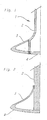
- Fig. 4 is a valve plate 4 with a molded collar-shaped Support shown.
Abstract
Description
Die Erfindung betrifft ein Leichtbauventil, insbesondere für einen Verbrennungsmotor, mit einem Schaft, einem Ventilkegel und einem Ventilteller, wobei Ventilkegel und Ventilteller gemeinsam einen Hohlraum bilden und die Wandstärken von Ventilteller und Ventilkegel unterschiedlich sind, bei dem
- der Ventilteller sich in einem radial innen liegenden Bereich gegen den Ventilschaft abstützt,
- Ventilkegel und Ventilschaft aus zwei verschiedenen, miteinander verbunden Bauteilen bestehen, also nicht einstükkig sind,
- der Ventilkegel an seinem oberen Ende am Ventilschaft fixiert ist.
- the valve disk is supported against the valve stem in a radially inner area,
- The valve cone and valve stem consist of two different, interconnected components, i.e. they are not in one piece,
- the valve plug is fixed to the valve stem at its upper end.
Ein aus DE 36 25 590 A bekanntes Ventil soll einen Beitrag zur Entwicklung einer Motorengattung mit wärmeisolierten Verbrennungsräumen darstellen. Hierzu ist der dem Brennraum zugewandte Ventilteller besonders dünnwandig ausgebildet. Diese Maßnahme soll eine geringe Wärmeaufnahme des Ventiltellers und entsprechend niedrige Wärmeverluste bewirken. Um die Dünnwandigkeit des Ventiltellers zu ermöglichen, sind in Verlängerung des Ventilschafts zusätzliche Bauteile als Abstützung zwischen Ventilteller und Ventilschaft vorgesehen. A valve known from DE 36 25 590 A is intended to contribute for the development of a motor type with heat-insulated Represent combustion rooms. This is the combustion chamber facing valve plate is particularly thin-walled. This measure aims at low heat absorption of the valve disk and cause correspondingly low heat losses. Around to allow the thin walls of the valve plate are in Extension of the valve stem additional components as a support provided between the valve plate and valve stem.
Leichtbauventile sind ferner bekannt z.B. aus der DE 19 60 331 A, der EP 0 091 097 A, der US 2,731,708 oder der US 1,294,416.Lightweight valves are also known e.g. from the DE 19 60 331 A, EP 0 091 097 A, US 2,731,708 or U.S. 1,294,416.
Bei der Entwicklung moderner Motoren wird verstärkt auch an eine elektromagnetische, pneumatische oder hydraulische Ansteuerung des Ventiltriebs gedacht. Die für derartige Ventiltriebe aufzubringende Antriebsleistung wächst exponentiell mit dem Gewicht der oszilierenden Massen, d.h. der Ventile. Daraus ergibt sich die Forderung, Leichtbauventile bezüglich des Gewichts weiter zu optimieren, d.h. insbesondere die Wandstärken weiter zu minimieren.The development of modern engines is also increasing an electromagnetic, pneumatic or hydraulic control of the valve train. The for such valve trains the drive power to be applied is growing exponentially with the weight of the oscillating masses, i.e. of the valves. Hence the requirement regarding lightweight valves to further optimize the weight, i.e. in particular to further minimize the wall thickness.
Bei den meisten bekannten Leichtbauventilen wird durch das Bestreben, im Inneren des Ventils einen möglichst großen Hohlraum zu schaffen, eine relativ große, nicht unterstützte Bodenfläche zum Brennraum hin gebildet, die im Betrieb - insbesondere bei minimierten Wandstärken - durch den Verbrennungsdruck deformiert wird. Die durch diese Verformungen entstehenden Verschiebungen an der Umfangsfläche des Ventilsitzes tragen zu einem vorzeitigen Verschleiß des Sitzes und zur zusätzlichen Beanspruchung des Ventils bei. Außerdem bewirken diese Verformungen eine zusätzliche Beanspruchung im Bereich der Fügestelle zwischen Ventilteller und Vetilkegel mit der Gefahr eines Aufplatzens der Verbindung.In most known lightweight valves, the Aim to have the largest possible inside the valve Cavity to create a relatively large, unsupported Floor area formed towards the combustion chamber, which in operation - especially with minimized wall thicknesses - due to the combustion pressure is deformed. The through these deformations resulting displacements on the peripheral surface of the valve seat contribute to premature wear of the seat and for additional stress on the valve. Also effect these deformations an additional load in the Area of the joint between the valve plate and valve cone with the risk of the connection bursting open.
Eine Abstützung des Ventiltellers ist an sich aus der US 2,439,240 bekannt. Die dort dargestellte Lösung ist jedoch bedingt durch die Ausbildung der Abstützung herstellungstechnisch aufwendig.A support of the valve plate is in itself from the US 2,439,240 known. However, the solution presented there is due to the design of the support in terms of manufacturing technology consuming.
Ein weiterer Lösungsansatz ist aus der US 2,371,548 bekannt. Dort wird der Ventilteller mittig abgestützt, wobei die von der Abstützung aufgenommenen Kräfte über ein innerhalb des Schafts angeordnetes Rohrstück in das Schaftende eingeleitet werden. Diese Anordnung ist aufwendig und erzielt nur teilweise den erwünschten Effekt einer minimalen Verformung des Ventilkopfes unter Last. Insbesondere ergibt sich aufgrund des Kraftflusses über den Schaft für diesen Lösungsansatz bei gleichen geometrischen Verhältnissen sogar eine Verschlechterung der Verformungswerte verglichen mit z.B. dem aus der EP-OS 091 097 bekannten Ventil.Another approach is known from US 2,371,548. There the valve disk is supported in the middle, with the by the forces absorbed via a within the Tube piece arranged in the shaft introduced into the shaft end become. This arrangement is complex and only partially achieved the desired effect of minimal deformation of the Valve head under load. In particular, it results from the force flow over the shaft for this approach even deterioration given the same geometric conditions the deformation values compared to e.g. the valve known from EP-OS 091 097.
Die Abstützung des Ventiltellers gegen den Schaft ist auch aus der DE 36 25 590 A bekannt. Nachteilig bei den dort offenbarten Lösungen ist jedoch, dass die Abstützung mit Hilfe eines zusätzlichen Zwischenstücks, das zwischen Ventilteller und Schaft fixiert ist, erfolgt und dass die Wandstärke des Ventiltellers sehr gering ist, so dass Verformungen des Ventilkopfes zu erwarten sind.The valve disc is also supported against the stem known from DE 36 25 590 A. A disadvantage of those disclosed there Solutions, however, is that with the support an additional adapter between the valve disc and shaft is fixed, and that the wall thickness of the Valve plate is very small, causing deformation of the valve head are to be expected.
Die Erfindung beschäftigt sich daher mit dem Problem, bei einem Leichtbauventil auf einfache Art und Weise die Steifigkeit des Ventilkopfes zu erhöhen und die Herstellung des Ventils zu erleichtern. The invention is therefore concerned with the problem of a lightweight valve the rigidity in a simple way to increase the valve head and manufacture the To facilitate the valve.
Dieses Problem wird bei gattungsgemäßen Ventilen durch eine
Ausbildung nach den jeweils gesamten Merkmalen mindestens
eines der Ansprüche 1 bis 3 gelöst. Vorteilhafte Weiterbildungen
sind Gegenstand der Unteransprüche.This problem is solved by a generic valve
Training according to the overall characteristics at least
one of
Mit erfindungsgemäßen Ventilen lassen sich Verformungswerte realisieren, die im Bereich der Werte von Ventilen mit einem Ventilkopf aus Vollmaterial liegen. Die Massenreduktion dieser Leichtbauventile beträgt mindestens 40% im Vergleich mit Vollmaterial-Stahlventilen.Deformation values can be achieved with valves according to the invention realize that in the range of values of valves with a Valve head made of solid material. The mass reduction of this Lightweight valves is at least 40% compared to Solid material steel valves.
Dabei stellt die Ausführung nach den Ansprüchen 1 bis 3 eine
weitgehende Abkehr von der bisher üblichen Bauform für
Leichtbauventile dar, da der Ventilkegel nicht mehr einstükkig
mit dem Ventilschaft ist, sondern als Einzelteil hergestellt
wird und der Ventilschaft sich - gegebenenfalls mit
vergrößertem Durchmesser - zum Ventilteller hin fortsetzt.The embodiment according to
Der Schaft ist vorzugsweise als gezogenes oder geschweißtes Rohr ausgeführt oder besteht aus Vollmaterial.The shaft is preferably drawn or welded Pipe made or made of solid material.
Die Fixierung des Ventilkegels am Schaft erfolgt vorzugsweise durch Löten oder Schweißen.The valve cone is preferably fixed to the stem by soldering or welding.
Unter 'radial innen' ist zu verstehen: entfernt vom Außendurchmesser des Ventiltellers. 'Radially inside' means: away from the outside diameter of the valve plate.
Durch das erfindungsgemäße Ventil wird ein Leichtbauventil geschaffen, das auch noch bei dünnen Wandstärken und entsprechend geringem Gewicht eine hohe Steifigkeit aufweist.The valve according to the invention becomes a lightweight valve created that even with thin walls and accordingly low weight and high rigidity.
Die Erfindung beruht auf dem Grundgedanken, die auf den Ventilteller wirkenden Gaskräfte durch direkte Abstützung des Ventiltellers gegen den Schaft aufzunehmen. Durch die Abstützung des Ventiltellers gegen den Ventilschaft entsteht in Verbindung mit dem Ventilkegel ein biegesteifes Rotationsflächentragwerk mit etwa dreieckförmigem Querschnitt.The invention is based on the basic idea of the valve disk acting gas forces by direct support of the Take valve plates against the shaft. By the support of the valve plate against the valve stem in connection with the valve cone a flexurally rigid rotating surface structure with an approximately triangular cross section.
Aus der US 4,834,036 ist ein Leichtbauventil bekannt, bei dem der Schaft bis in den Bereich des Ventiltellers durchgeht, bei dem Ventilkopf handelt es sich jedoch um ein leichtes, gegossenes oder geschmiedetes Vollmaterial auf Titanbasis wie Titanaluminid, so dass dieses Ventil gattungsgemäß nicht zu den erfindungsgemäßen Hohlventilen gehört.A lightweight valve is known from US 4,834,036 which the shaft extends into the area of the valve plate, however, the valve head is a light, cast or forged solid material based on titanium like titanium aluminide, so this valve is generic does not belong to the hollow valves according to the invention.
Zwar ist außerdem noch ein Ventil aus der US 1,506,900 aus dem Jahr 1924 bekannt, das einen ähnlichen Aufbau aufweist, von dem sich die Erfindung allerdings durch ein unterschiedliches Wandstärkenverhältnis und eine andere Ausbildung bezüglich der Anbindung des Schaftendes an den Ventilteller unterscheidet. Die dort offenbarte, relativ dünne Wandstärke des Ventiltellers verglichen mit dem Ventilkegel ist festigkeitsmäßig ungünstig, ebenso der Durchbruch im Ventilteller zur Aufnahme des Ventilschaftendes. A valve from US 1,506,900 is also still out known in 1924, which has a similar structure, from which the invention differs, however, by a different one Wall thickness ratio and other training related the connection of the shaft end to the valve plate different. The relatively thin wall thickness disclosed there of the valve disc compared to the valve cone is firm unfavorable, as well as the breakthrough in the valve plate for receiving the valve stem end.
Die Erfindung wird im folgenden anhand von Ausführungsbeispielen näher erläutert. Es zeigt:
- Fig. 1
- ein erfindungsgemäßes Ventil im Querschnitt,
- Fig. 2
- ein weiteres Ausführungsbeispiel, Ventilteller und Kegel zweistückig,
- Fig. 3
- ein Ausführungsbeispiel mit einer Zentrierung für den Schaftfuß und
- Fig. 4
- ein Ausführungsbeispiel mit einer am Ventilteller angeformten Abstützung.
- Fig. 1
- a valve according to the invention in cross section,
- Fig. 2
- another embodiment, valve disc and cone in two pieces,
- Fig. 3
- an embodiment with a centering for the shaft foot and
- Fig. 4
- an embodiment with a molded on the valve plate support.
Ein Ventil 1 für einen Verbrennungsmotor besteht aus einem
Schaft 2, einem nicht dargestellten Ventilfuß, einem trichterförmigen
Ventilkegel 3 und einem einstückig mit dem Ventilkegel
hergestellten Ventilteller 4. Der Durchmesser des
Schafts ist auf Höhe des Ventilkegels 3 erweitert. An seinem
unteren Ende ist der Schaft 2 mit dem Ventilteller 4 verschweißt.
Der Ventilkegel 3 ist an seinem oberen Ende mit
dem Schaft 2 verschweißt. Der Ventilkegel 3, der Ventilteller
4 und das beide verbindende untere, erweiterte Schaftende
bilden gemeinsam ein biegesteifes Rotationsflächentragwerk.
Die Wandstärke des Ventilkegels 3 ist kleiner als die
Wandstärke des Ventiltellers 4.A
Bei der in Fig. 2 dargestellten Ausführung sind Ventilteller
4 und Ventilkegel 3 nicht einstückig, sondern durch eine
Schweißnaht miteinander verbunden. Der Schaft besteht aus
Vollmaterial. Dabei kann der Schaft unterhalb der Schweißnaht
auch einen kleineren Durchmesser aufweisen als im Bereich
oberhalb der Schweißnaht.In the embodiment shown in Fig. 2 are
In Fig. 3 sind Ventilteller 4 und Ventilkegel 3 einstückig
uund im Ventilteller 4 ist eine Zentrierung für das Ende des
Schafts 2 vorgesehen. Eine Schweißverbindung ist nur zwischen
dem oberen Ende des Ventilkegels 3 und dem Schaft vorgesehen.
Auch hier ist die Wandstärke des Ventiltellers 4
größer als die Wandstärke des Ventilkegels 3.In Fig. 3
In Fig. 4 ist ein Ventilteller 4 mit einer angeformten bundförmigen
Abstützung dargestellt.In Fig. 4 is a
Claims (6)
- a1:
- einem Ventilschaft (2),
- a2:
- einem trichterförmigen Ventilkegel (3) und
- a3:
- einem Ventilteller (4),
- b:
- der trichterförmige Ventilkegel (3) im Bereich seines engsten Querschnittes mit dem Ventilschaft (2),
- c:
- der Ventilteller (4) radial außen mit dem trichterförmigen Ventilkegel (3),
- d:
- die Wandstärken von Ventilteller (4) und Ventilkegel (3) relativ zum Schaftdurchmesser ein Verhältnis von größer oder gleich 1:3 aufweisen,
- e:
- die Wandstärke des Ventilkegels kleiner als diejenige des Ventiltellers (4), jedoch größer oder gleich 0,7 ist,
- f:
- der Ventilschaft (2) den Ventilkegel (3) durchragt und mit seinem Ende an dem Ventilteller (4) anliegt, wobei der Ventilteller (4) keinen Durchbruch zur Aufnahme des Ventilschaftendes aufweist.
- a1:
- a valve stem (2),
- a2:
- a funnel-shaped valve cone (3) and
- a3:
- a valve plate (4),
- b:
- the funnel-shaped valve cone (3) in the area of its narrowest cross section with the valve stem (2),
- c:
- the valve disc (4) radially outside with the funnel-shaped valve cone (3),
- d:
- the wall thicknesses of valve disc (4) and valve plug (3) have a ratio of greater than or equal to 1: 3 relative to the stem diameter,
- e:
- the wall thickness of the valve cone is smaller than that of the valve plate (4), but is greater than or equal to 0.7,
- f:
- the valve stem (2) projects through the valve cone (3) and its end rests on the valve plate (4), the valve plate (4) having no opening for receiving the valve stem end.
- a1:
- einem Ventilschaft (2),
- a2:
- einem trichterförmigen Ventilkegel (3) und
- a3:
- einem Ventilteller (4),
- b:
- der trichterförmige Ventilkegel (3) im Bereich seines engsten Querschnittes mit dem Ventilschaft (2),
- c:
- der Ventilteller (4) radial außen mit dem trichterförmigen Ventilkegel (3),
- d:
- die Wandstärken von Ventilteller (4) und Ventilkegel (3) relativ zum Schaftdurchmesser ein Verhältnis von kleiner 1:3 aufweisen,
- e:
- die Wandstärke des Ventilkegels kleiner als diejenige des Ventiltellers (4), jedoch größer/gleich 0,7 ist,
- f:
- der Ventilschaft (2) den Ventilkegel (3) durchragt und mit seinem Ende an dem Ventilteller (4) anliegt, wobei der Ventilteller (4) keinen Durchbruch zur Aufnahme des Ventilschaftendes aufweist.
- a1:
- a valve stem (2),
- a2:
- a funnel-shaped valve cone (3) and
- a3:
- a valve plate (4),
- b:
- the funnel-shaped valve cone (3) in the area of its narrowest cross section with the valve stem (2),
- c:
- the valve disc (4) radially outside with the funnel-shaped valve cone (3),
- d:
- the wall thicknesses of valve disc (4) and valve cone (3) have a ratio of less than 1: 3 relative to the stem diameter,
- e:
- the wall thickness of the valve cone is smaller than that of the valve disc (4), but is greater than or equal to 0.7,
- f:
- the valve stem (2) projects through the valve cone (3) and its end rests on the valve plate (4), the valve plate (4) having no opening for receiving the valve stem end.
- a1:
- einem Ventilschaft (2),
- a2:
- einem trichterförmigen Ventilkegel (3) und
- a3:
- einem Ventilteller (4),
- b:
- der trichterförmige Ventilkegel (3) im Bereich seines engsten Querschnittes mit dem Ventilschaft (2),
- c:
- der Ventilteller (4) radial außen mit dem trichterförmigen Ventilkegel (3),
- d:
- die Wandstärken von Ventilteller (4) und Ventilkegel (3)
relativ zum Schaftdurchmesser ein Verhältnis von größer oder gleich 1:3 aufweisen, - e:
- das Verhältnis der Wandstärken von Ventilkegel (3) und Ventilteller (4) kleiner 0,7 ist,
- f:
- der Ventilschaft (2) den Ventilkegel (3) durchragt und mit seinem Ende an dem Ventilteller (4) anliegt, wobei der Ventilteller (4) keinen Durchbruch zur Aufnahme des Ventilschaftendes aufweist.
- a1:
- a valve stem (2),
- a2:
- a funnel-shaped valve cone (3) and
- a3:
- a valve plate (4),
- b:
- the funnel-shaped valve cone (3) in the area of its narrowest cross section with the valve stem (2),
- c:
- the valve disc (4) radially outside with the funnel-shaped valve cone (3),
- d:
- the wall thickness of the valve disc (4) and valve cone (3)
have a ratio of greater than or equal to 1: 3 relative to the shaft diameter, - e:
- the ratio of the wall thicknesses of valve cone (3) and valve disc (4) is less than 0.7,
- f:
- the valve stem (2) projects through the valve cone (3) and its end rests on the valve plate (4), the valve plate (4) having no opening for receiving the valve stem end.
dadurch gekennzeichnet, dass der Ventilschaft (2) als gezogenes oder geschweißtes Rohr ausgeführt ist.Lightweight valve according to one of the preceding claims,
characterized in that the valve stem (2) is designed as a drawn or welded tube.
dadurch gekennzeichnet, dass der Ventilschaft (2) an dem Ventilteller (4) fixiert ist.Valve plate according to one of the preceding claims,
characterized in that the valve stem (2) is fixed to the valve plate (4).
dadurch gekennzeichnet, dass Ventilkegel (3) und Ventilteller (4) einstückig ausgebildet sind.Lightweight valve according to one of the preceding claims,
characterized in that the valve cone (3) and valve disc (4) are formed in one piece.
Applications Claiming Priority (3)
| Application Number | Priority Date | Filing Date | Title |
|---|---|---|---|
| DE19804053 | 1998-02-03 | ||
| DE19804053A DE19804053A1 (en) | 1998-02-03 | 1998-02-03 | Lightweight valve |
| EP99908830A EP1053388B1 (en) | 1998-02-03 | 1999-01-28 | Lightweight valve |
Related Parent Applications (1)
| Application Number | Title | Priority Date | Filing Date |
|---|---|---|---|
| EP99908830.5 Division | 1999-01-28 |
Publications (1)
| Publication Number | Publication Date |
|---|---|
| EP1359292A1 true EP1359292A1 (en) | 2003-11-05 |
Family
ID=7856414
Family Applications (2)
| Application Number | Title | Priority Date | Filing Date |
|---|---|---|---|
| EP99908830A Expired - Lifetime EP1053388B1 (en) | 1998-02-03 | 1999-01-28 | Lightweight valve |
| EP03014001A Withdrawn EP1359292A1 (en) | 1998-02-03 | 1999-01-28 | Lightweight valve |
Family Applications Before (1)
| Application Number | Title | Priority Date | Filing Date |
|---|---|---|---|
| EP99908830A Expired - Lifetime EP1053388B1 (en) | 1998-02-03 | 1999-01-28 | Lightweight valve |
Country Status (7)
| Country | Link |
|---|---|
| US (1) | US6354258B1 (en) |
| EP (2) | EP1053388B1 (en) |
| JP (1) | JP4282900B2 (en) |
| AR (1) | AR018055A1 (en) |
| BR (1) | BR9908554A (en) |
| DE (2) | DE19804053A1 (en) |
| WO (1) | WO1999040295A1 (en) |
Cited By (5)
| Publication number | Priority date | Publication date | Assignee | Title |
|---|---|---|---|---|
| WO2005049977A1 (en) * | 2003-11-19 | 2005-06-02 | Daimlerchrysler Ag | Lightweight valve |
| WO2005049979A1 (en) * | 2003-11-19 | 2005-06-02 | Daimlerchrysler Ag | Lightweight valve |
| US7941922B2 (en) | 2003-11-19 | 2011-05-17 | Daimler Ag | Method of manufacturing a lightweight valve |
| WO2012168136A1 (en) | 2011-06-08 | 2012-12-13 | Mahle International Gmbh | Method for producing a hollow metal valve with improved cooling |
| DE102012209187A1 (en) | 2011-06-08 | 2012-12-13 | Mahle International Gmbh | Method for manufacturing metallic hollow valve of internal combustion engine, involves introducing hole into slug, and partially hollowing valve head by electrochemical removal such that cavity is filled with fluid, and forging hollow valve |
Families Citing this family (21)
| Publication number | Priority date | Publication date | Assignee | Title |
|---|---|---|---|---|
| DE50000201D1 (en) * | 2000-09-29 | 2002-07-11 | Ford Global Tech Inc | Valve for internal combustion engines |
| WO2003056142A1 (en) * | 2001-12-27 | 2003-07-10 | Mahle Ventiltrieb Gmbh | Gas exchange valve of an internal combustion engine, comprising a hollow valve head |
| DE10209770A1 (en) * | 2002-03-05 | 2003-10-09 | Daimler Chrysler Ag | lightweight valve |
| DE10217719A1 (en) * | 2002-04-20 | 2003-11-06 | Mahle Ventiltrieb Gmbh | Movable closure body of a valve exposed to hot gases |
| DE10354076B4 (en) * | 2003-11-19 | 2006-03-09 | Daimlerchrysler Ag | lightweight valve |
| DE10354074B4 (en) * | 2003-11-19 | 2006-01-26 | Daimlerchrysler Ag | lightweight valve |
| DE102004010309A1 (en) * | 2004-03-03 | 2005-09-22 | Mahle Ventiltrieb Gmbh | Gas exchange valve of an internal combustion engine |
| US7240895B2 (en) | 2004-03-03 | 2007-07-10 | Mahle Ventiltrieb Gmbh | Gas exchange valve for an internal combustion engine |
| US20060118177A1 (en) * | 2004-12-07 | 2006-06-08 | Ucman Robert C | Coated valve and method of making same |
| DE102005005041A1 (en) * | 2005-02-03 | 2006-08-10 | Märkisches Werk GmbH | Valve for controlling the gas exchange, in particular in internal combustion engines |
| DE102005027130A1 (en) | 2005-06-11 | 2006-12-14 | Mahle International Gmbh | Gas exchange valve of an internal combustion engine |
| DE102006049844A1 (en) * | 2006-10-20 | 2008-04-24 | Gkss-Forschungszentrum Geesthacht Gmbh | Process for the production of components for internal combustion engines or turbines |
| DE102006061128B4 (en) * | 2006-12-22 | 2015-06-11 | Mahle International Gmbh | Gas exchange valve of an internal combustion engine |
| DE102006061127B4 (en) * | 2006-12-22 | 2016-07-14 | Mahle International Gmbh | Metallic lightweight valve of an internal combustion engine |
| DE102010051871A1 (en) | 2010-11-22 | 2012-05-24 | Märkisches Werk GmbH | Method for manufacturing valves for gas exchange, involves forming valve head and valve stem as hollow section, particularly for internal combustion engines |
| DE102013203443A1 (en) * | 2013-02-28 | 2014-08-28 | Mahle International Gmbh | Metallic hollow valve |
| DE102013203441A1 (en) | 2013-02-28 | 2014-08-28 | Bayerische Motoren Werke Aktiengesellschaft | Operating method for a single-axle roll stabilization system of a two-axle, two-lane vehicle |
| DE102013210900A1 (en) | 2013-06-11 | 2014-12-11 | Mahle International Gmbh | Gas exchange valve of an internal combustion engine |
| DE102013210899A1 (en) | 2013-06-11 | 2014-12-11 | Mahle International Gmbh | Method for producing a built-up hollow valve |
| DE102013216188A1 (en) * | 2013-08-14 | 2015-03-12 | Mahle International Gmbh | Light alloy inlet valve |
| CN110914520B (en) * | 2018-03-20 | 2021-11-16 | 日锻汽门株式会社 | Hollow lift valve for exhaust |
Citations (2)
| Publication number | Priority date | Publication date | Assignee | Title |
|---|---|---|---|---|
| US1506900A (en) * | 1922-06-29 | 1924-09-02 | Greiner Adolph | Valve |
| DE910492C (en) * | 1951-10-03 | 1954-05-03 | Wilhelm Schmidt | Hollow poppet valve |
Family Cites Families (17)
| Publication number | Priority date | Publication date | Assignee | Title |
|---|---|---|---|---|
| US2734008A (en) * | 1956-02-07 | Method of making heat treating and hardening valves | ||
| US1294416A (en) | 1918-01-02 | 1919-02-18 | Pfanstiehl Company Inc | Valve and method of making the same. |
| US1557022A (en) * | 1922-11-03 | 1925-10-13 | Aeromarine Plane & Motor Compa | Valve and method of making same |
| US1727621A (en) * | 1928-02-18 | 1929-09-10 | Gen Motors Corp | Exhaust valve |
| DE762642C (en) * | 1942-08-21 | 1954-08-02 | Daimler Benz Ag | Exhaust valve for internal combustion engines, especially aircraft engines |
| US2371548A (en) | 1943-12-06 | 1945-03-13 | Thomas F Saffady | Valve |
| US2398514A (en) | 1944-10-14 | 1946-04-16 | Wilhelm B Bronander | Internal-combustion engine |
| US2439240A (en) | 1945-01-18 | 1948-04-06 | Thompson Prod Inc | Braced head dome valve |
| US2731708A (en) | 1952-10-31 | 1956-01-24 | Teves Kg Alfred | Process for manufacture of hollow poppet valves especially for internal-combustion engines |
| DE1960331A1 (en) | 1969-12-02 | 1971-06-03 | Porsche Kg | Cone valve, especially for internal combustion engines |
| JPS58151306U (en) | 1982-04-05 | 1983-10-11 | 日産自動車株式会社 | Internal combustion engine intake and exhaust valves |
| DE3233392A1 (en) * | 1982-08-31 | 1984-03-01 | Gebrüder Sulzer AG, 8401 Winterthur | Disc valve for a gas-changing valve |
| JPS60169611A (en) | 1984-02-14 | 1985-09-03 | Mitsubishi Heavy Ind Ltd | Exhaust valve of internal-combustion engine |
| DE3625590A1 (en) * | 1986-07-29 | 1988-02-04 | Odilo Schwaiger | Valves for internal combustion engines |
| DE3625560A1 (en) | 1986-07-29 | 1988-02-04 | Siemens Ag | Gas laser |
| JPS643007U (en) | 1987-06-25 | 1989-01-10 | ||
| US5771852A (en) | 1997-03-04 | 1998-06-30 | Trw Inc. | Poppet valve with embossed neck structure |
-
1998
- 1998-02-03 DE DE19804053A patent/DE19804053A1/en not_active Ceased
-
1999
- 1999-01-28 BR BR9908554-2A patent/BR9908554A/en not_active IP Right Cessation
- 1999-01-28 DE DE59908022T patent/DE59908022D1/en not_active Expired - Lifetime
- 1999-01-28 EP EP99908830A patent/EP1053388B1/en not_active Expired - Lifetime
- 1999-01-28 EP EP03014001A patent/EP1359292A1/en not_active Withdrawn
- 1999-01-28 WO PCT/EP1999/000561 patent/WO1999040295A1/en active IP Right Grant
- 1999-01-28 JP JP2000530689A patent/JP4282900B2/en not_active Expired - Fee Related
- 1999-01-28 US US09/601,497 patent/US6354258B1/en not_active Expired - Fee Related
- 1999-02-03 AR ARP990100450A patent/AR018055A1/en unknown
Patent Citations (2)
| Publication number | Priority date | Publication date | Assignee | Title |
|---|---|---|---|---|
| US1506900A (en) * | 1922-06-29 | 1924-09-02 | Greiner Adolph | Valve |
| DE910492C (en) * | 1951-10-03 | 1954-05-03 | Wilhelm Schmidt | Hollow poppet valve |
Cited By (8)
| Publication number | Priority date | Publication date | Assignee | Title |
|---|---|---|---|---|
| WO2005049977A1 (en) * | 2003-11-19 | 2005-06-02 | Daimlerchrysler Ag | Lightweight valve |
| WO2005049979A1 (en) * | 2003-11-19 | 2005-06-02 | Daimlerchrysler Ag | Lightweight valve |
| US7862007B2 (en) | 2003-11-19 | 2011-01-04 | Daimler Ag | Lightweight valve |
| US7905468B2 (en) | 2003-11-19 | 2011-03-15 | Daimler Ag | Lightweight valve |
| US7941922B2 (en) | 2003-11-19 | 2011-05-17 | Daimler Ag | Method of manufacturing a lightweight valve |
| WO2012168136A1 (en) | 2011-06-08 | 2012-12-13 | Mahle International Gmbh | Method for producing a hollow metal valve with improved cooling |
| DE102012209187A1 (en) | 2011-06-08 | 2012-12-13 | Mahle International Gmbh | Method for manufacturing metallic hollow valve of internal combustion engine, involves introducing hole into slug, and partially hollowing valve head by electrochemical removal such that cavity is filled with fluid, and forging hollow valve |
| DE102011077198A1 (en) | 2011-06-08 | 2012-12-13 | Mahle International Gmbh | Method for producing a metal hollow valve with improved cooling |
Also Published As
| Publication number | Publication date |
|---|---|
| DE19804053A1 (en) | 1999-08-05 |
| BR9908554A (en) | 2001-10-30 |
| AR018055A1 (en) | 2001-10-31 |
| JP4282900B2 (en) | 2009-06-24 |
| WO1999040295A1 (en) | 1999-08-12 |
| US6354258B1 (en) | 2002-03-12 |
| EP1053388B1 (en) | 2003-12-10 |
| DE59908022D1 (en) | 2004-01-22 |
| JP2002502928A (en) | 2002-01-29 |
| EP1053388A1 (en) | 2000-11-22 |
Similar Documents
| Publication | Publication Date | Title |
|---|---|---|
| EP1053388B1 (en) | Lightweight valve | |
| EP2089611B1 (en) | Turbocharger and corresponding fabrication process | |
| EP2029318B1 (en) | Method for the production of a single part piston | |
| EP0903465A1 (en) | Compressor wheel-shaft connection for high speed turbomachinery | |
| DE4218624A1 (en) | MECHANICAL ELEMENT WITH A SHAFT IN A RECESSING LINK WITH A PRESS FIT AND ITS PRODUCTION METHOD | |
| EP0265663A1 (en) | Method of producing a camshaft, as well as a camshaft made from a tube, and elements placed thereon | |
| DE3544143C2 (en) | ||
| EP1805406A1 (en) | Method for the production of a piston of an internal combustion engine in order to form a reinforcement of a combustion chamber cavity of the piston | |
| DE10311205B3 (en) | Guiding device for a radial turbine of a turbocharger of a lifting piston I.C. engine operating with heavy oil has blades with shafts positioned in a housing part of the device facing a compressor of the turbocharger | |
| EP1096112B1 (en) | Device for changing the timing of gas exchange valves of a combustion engine, especially hydraulic vane cell timer | |
| WO2009100749A1 (en) | Connection of a shaft to a rotating component | |
| DE3346056A1 (en) | Method for the production of a built-up camshaft | |
| DE102007031581A1 (en) | Piston of an internal combustion engine with an increased inclination of the box walls of the piston | |
| EP0271638B1 (en) | Cast shaft, in particular camshaft | |
| DE10354085A1 (en) | lightweight valve | |
| DE102007005216B4 (en) | vacuum pump | |
| DE3737600A1 (en) | METHOD FOR PRODUCING ASSEMBLED CRANKSHAFT BY EXPANDING SLEEVES ARRANGED IN DIVIDED PINS | |
| DE10354086B4 (en) | lightweight valve | |
| EP1419001B1 (en) | Housing | |
| DE102006029040A1 (en) | Piston for use in reciprocating internal combustion engine of vehicle, has piston pin bearing with bearing sections for bearing piston pin, and piston skirt produced from sheet material, where sections are formed by double wall structure | |
| DE3733910C2 (en) | ||
| DE2258090A1 (en) | COMPRESSIBLE METAL BELLOW | |
| AT5130U1 (en) | PUSH ROD, IN PARTICULAR FOR A VALVE ACTUATING DEVICE OF AN INTERNAL COMBUSTION ENGINE | |
| EP0326606A1 (en) | Composite crankshaft and process for manufacturing it | |
| DE102014106470B4 (en) | Bearing bush for a chassis or transmission component of a motor vehicle |
Legal Events
| Date | Code | Title | Description |
|---|---|---|---|
| PUAI | Public reference made under article 153(3) epc to a published international application that has entered the european phase |
Free format text: ORIGINAL CODE: 0009012 |
|
| AC | Divisional application: reference to earlier application |
Ref document number: 1053388 Country of ref document: EP Kind code of ref document: P |
|
| AK | Designated contracting states |
Kind code of ref document: A1 Designated state(s): AT BE BG CH CY CZ DE DK EE ES FI FR GB GR HU IE IT LI LU MC NL PT RO SE SI SK TR |
|
| 17P | Request for examination filed |
Effective date: 20040212 |
|
| AKX | Designation fees paid |
Designated state(s): DE FR GB IT |
|
| 17Q | First examination report despatched |
Effective date: 20041125 |
|
| STAA | Information on the status of an ep patent application or granted ep patent |
Free format text: STATUS: THE APPLICATION IS DEEMED TO BE WITHDRAWN |
|
| 18D | Application deemed to be withdrawn |
Effective date: 20090331 |