EP1359074A1 - Nozzle structure of washer fluid injector - Google Patents
Nozzle structure of washer fluid injector Download PDFInfo
- Publication number
- EP1359074A1 EP1359074A1 EP01967734A EP01967734A EP1359074A1 EP 1359074 A1 EP1359074 A1 EP 1359074A1 EP 01967734 A EP01967734 A EP 01967734A EP 01967734 A EP01967734 A EP 01967734A EP 1359074 A1 EP1359074 A1 EP 1359074A1
- Authority
- EP
- European Patent Office
- Prior art keywords
- washer fluid
- nozzle
- portions
- injection port
- injection
- Prior art date
- Legal status (The legal status is an assumption and is not a legal conclusion. Google has not performed a legal analysis and makes no representation as to the accuracy of the status listed.)
- Withdrawn
Links
Images




Classifications
-
- B—PERFORMING OPERATIONS; TRANSPORTING
- B05—SPRAYING OR ATOMISING IN GENERAL; APPLYING FLUENT MATERIALS TO SURFACES, IN GENERAL
- B05B—SPRAYING APPARATUS; ATOMISING APPARATUS; NOZZLES
- B05B1/00—Nozzles, spray heads or other outlets, with or without auxiliary devices such as valves, heating means
- B05B1/28—Nozzles, spray heads or other outlets, with or without auxiliary devices such as valves, heating means with integral means for shielding the discharged liquid or other fluent material, e.g. to limit area of spray; with integral means for catching drips or collecting surplus liquid or other fluent material
-
- B—PERFORMING OPERATIONS; TRANSPORTING
- B05—SPRAYING OR ATOMISING IN GENERAL; APPLYING FLUENT MATERIALS TO SURFACES, IN GENERAL
- B05B—SPRAYING APPARATUS; ATOMISING APPARATUS; NOZZLES
- B05B1/00—Nozzles, spray heads or other outlets, with or without auxiliary devices such as valves, heating means
- B05B1/02—Nozzles, spray heads or other outlets, with or without auxiliary devices such as valves, heating means designed to produce a jet, spray, or other discharge of particular shape or nature, e.g. in single drops, or having an outlet of particular shape
- B05B1/04—Nozzles, spray heads or other outlets, with or without auxiliary devices such as valves, heating means designed to produce a jet, spray, or other discharge of particular shape or nature, e.g. in single drops, or having an outlet of particular shape in flat form, e.g. fan-like, sheet-like
-
- B—PERFORMING OPERATIONS; TRANSPORTING
- B05—SPRAYING OR ATOMISING IN GENERAL; APPLYING FLUENT MATERIALS TO SURFACES, IN GENERAL
- B05B—SPRAYING APPARATUS; ATOMISING APPARATUS; NOZZLES
- B05B1/00—Nozzles, spray heads or other outlets, with or without auxiliary devices such as valves, heating means
- B05B1/02—Nozzles, spray heads or other outlets, with or without auxiliary devices such as valves, heating means designed to produce a jet, spray, or other discharge of particular shape or nature, e.g. in single drops, or having an outlet of particular shape
- B05B1/04—Nozzles, spray heads or other outlets, with or without auxiliary devices such as valves, heating means designed to produce a jet, spray, or other discharge of particular shape or nature, e.g. in single drops, or having an outlet of particular shape in flat form, e.g. fan-like, sheet-like
- B05B1/042—Outlets having two planes of symmetry perpendicular to each other, one of them defining the plane of the jet
-
- B—PERFORMING OPERATIONS; TRANSPORTING
- B60—VEHICLES IN GENERAL
- B60S—SERVICING, CLEANING, REPAIRING, SUPPORTING, LIFTING, OR MANOEUVRING OF VEHICLES, NOT OTHERWISE PROVIDED FOR
- B60S1/00—Cleaning of vehicles
- B60S1/02—Cleaning windscreens, windows or optical devices
- B60S1/46—Cleaning windscreens, windows or optical devices using liquid; Windscreen washers
- B60S1/48—Liquid supply therefor
- B60S1/52—Arrangement of nozzles; Liquid spreading means
Definitions
- the present invention relates to a technical field of a nozzle structure in a washer fluid injection apparatus which supplies a washer fluid to a windshield of a vehicle.
- a washer fluid supplying apparatus is provided in the vicinity of a window surface, for example, in the vicinity of a windshield of a vehicle, and a structure is made such that a soil on the windshield is washed by injection of the washer fluid onto the windshield as occasion demands and a wiping operation by a wiper blade.
- various kinds of proposals have been conventionally made with respect to a shape of the injection nozzle for improving a washing efficiency.
- a diffusion type nozzle in which an injection port of the washer fluid is formed in a long rectangular shape in a lateral direction.
- the washer fluid is applied to a wide range of the window surface and it is possible to efficiently wipe and wash the windshield by the wiper blade even with a little fluid amount.
- a grain diameter of the washer fluid becomes smaller as the washer fluid is apart from a nozzle center (corresponding to a preset injection hitting point).
- the range in which the washer fluid is applied to the window surface is previously set so as to be optimum in a stopping state of the vehicle. Accordingly, in the case of injecting the washer fluid while the vehicle travels, the application range of the washer fluid tends to be lower than the preset range.
- a distribution of the grain diameter of the washer fluid is uniform in a vertical direction, as shown in Fig. 6A and a washer fluid drop of a smaller grain diameter which has been injected to an outer periphery side (an outer side portion) of the fluid application range is largely affected by an air flow and furthermore, the influence of the air flow becomes more remarkable as a traveling speed of the vehicle becomes higher. Accordingly, on the basis of the actual case mentioned above, it is possible to set the fluid application range previously taking into consideration the air flow at a time when the vehicle travels, however, in this structure, the fluid application range at the stopping time is displaced to the high position, which is inappropriate position.
- JP-A Japanese Patent Application Laid-Open
- JP-A Japanese Patent Application Laid-Open
- JP-A Japanese Patent Application Laid-Open
- a protruding amount of lip portions respectively formed in a protruding manner in upper and lower edge portions of an injection port for the purpose of regulating an injection range of the washer fluid is set so that the lip portion in the lower side is shorter than the lip portion in the upper side, thereby regulating the injection of the washer fluid in such a manner as to prevent the injection of the washer fluid to the upper side from becoming far from a center of the nozzle, so that the air flow at the vehicle traveling time is hard to affect the washer fluid.
- the lip portion in the upper side is protruded in comparison with the lip portion in the lower side, however, since the nozzle itself is a small member, the protruding lip portion in the upper side is easily affected by an external world. Namely, there is a problem that a sense of unity in design is reduced at a time when the nozzle is assembled in a nozzle body, and a problem to be solved by the present invention exists here.
- the conventional nozzle body mentioned above is formed by machining of a metal material, and is expensive in view of cost.
- the nozzle is formed by a resin material, however, in the case that the nozzle having the different protruding lengths between the upper and lower lip portions as described above, it is supposed that a force applied from the external world tends to be concentrated in the protruding upper lip portion, so that it is impossible to employ the structure having this shape, and a problem to be solved also exists here.
- a nozzle structure in a washer fluid injection apparatus comprising: a tubular hole portion communicated with a washer fluid supply side; an injection port communicated with the tubular hole portion and formed long from side to side; and a pair of upper and lower lip portions respectively protruding in an injection direction from upper and lower edge portions of the injection port so as to set an injection direction of a washer fluid, wherein a protruding tip portion of the lower lip portion is positioned below a lower edge of the injection port.
- the protruding amounts of the upper and lower lip portions can be set to substantially the same size, whereby it is possible to improve a design property.
- the lower lip portion can be formed in a stepped shape such that the protruding tip portion is positioned in a lower side.
- the lower lip portion can be formed in an inclined shape such that the protruding tip portion is positioned in a lower side.
- the nozzle can be formed by a resin material, and can be formed with reinforcing portions by connecting portions over left and right end portions of the upper and lower lip portions to each other in abridge formation manner.
- the lipportions are reinforced and a high strength can be obtained despite of the nozzle made of the resin.
- a step surface of the lower lip portion is formed flush with the tip surfaces of the reinforcing portions. Accordingly, it is easy to set the step surface in forming a mold.
- reference numerals 1, 2 denote wiper arms on a driver's and a passenger's seat sides of a wiper apparatus. Respective base end portions of the wiper arms 1, 2 are integrally mounted to protruding tip portions of wiper shafts 3, 4 which are arranged on the driver's and passenger's seat sides in a front panel P of the vehicle rotatably and in an upward protruding state. Wiper blades 5, 6 are detachably attached to tip portions of the respective wiper arms 1, 2, and these wiper blades 5, 6 are set such that the wiper blades 5, 6 are brought into elastic contact with a windshield FW by a biasing spring(not shown).
- the wiper blades 5, 6 in the tip portions of the wiper arms 1, 2 are reciprocated and reverted on the windshield FW. Accordingly, the respective wiper blades 5, 6 are set such as to respectively slide between a lower reverse position and an upper reverse position of the windshield FW so as to wipe the window surface.
- Reference numeral 7 denotes a pair of injection nozzles for injecting and supplying a washer fluid toward the windsheild FW on the driver's and the passenger's seat sides. These injection nozzles 7 are arranged at respective forward positions of the corresponding wiper shafts 3, 4 on the driver's and the passenger's seat sides on the front panel P mentioned above.
- a nozzle body 8 constituting the injection nozzle 7 is provided with a holder portion 8a in which a resin nozzle 9 embodied on the basis of the present invention is incorporated, and a connection portion 8b which is integrally extended from a lower end portion of the holder portion 8a and is used for mounting to an inner side of the front panel P in an immersing manner. Further, in the holder portion 8a, there are formed an inclined window opposing surface 8c facing to the side of the windshield FW, and a mounting recess portion 8d recessed from a side of the window opposing surface 8c, where the nozzle 9 is assembled in such a manner that a position of the nozzle 9 can be freely adjusted.
- a tubular hole 8e serving as a flow passage for the washer fluid is formed inside the connection portion 8b, and the mounting recess portion 8d and the connection portion tubular hole 8e are communicated via a communication hole 8f having a narrow diameter and formed in the side of the holder portion 8a.
- a pair of hook portions 8g for mounting to mounting holes pierced on the front panel P in a come-off preventing manner and detachably.
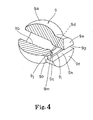
- the nozzle 9 is structured such that a tubular hole portion 9b in a washer fluid supply side, a throttle hole portion 9c connected to the tubular hole portion 9b, and an injection port 9d formed in a transversely long shape (formed in a rectangular shape in a horizontal direction in the present embodiment) in a washer fluid injection side tip portion of the throttle hole portion 9c are formed in a center portion of a spherical body 9a inward fitted to the nozzle body mounting recess portion 8d so as to be communicated with each other.
- a pair of upper and lower lip portions 9e, 9f respectively protruding in the washer fluid injecting direction are formed from upper and lower edge portions of the injection port 9d, and an injecting direction of the washer fluid injected from the injection port 9d is set by the lip portions 9e, 9f, whereby the washer fluid is set so as to be applied to a periphery around a preset injection hitting point of the windshield FW in a diffusion shape.
- each of a pair of upper and lower lip portions 9e, 9f is formed in an approximately semicircular columnar shape, and is formed such that an outer diameter thereof is smaller than an outer diameter of the spherical portion 9a.
- a protruding length of each of the lip portions 9e, 9f is set to the same length.
- the injection direction of the washer fluid is set by inner side surfaces 9g, 9h opposing to each other in a vertical direction.
- a step surface 9i is formed in the inner side surface 9h of the lower lip portion 9f in accordance with the present embodiment so as to form a step shape in the vertical direction, and the protruding tip portion of the inner side surface 9h is positioned in a lower position than a lower edge of the injection port 9d.
- a distance between a position of a nozzle center O and a position of a leading end of the upper lip portion inner side surface 9g is set smaller than a distance between the position of the nozzle center O and a position of the lower lip portion inner side surface 9h, whereby, as described later, the washer fluid injected from the injection port 9d is injected to a portion closer to the side of the center O of the nozzle 9 in the washer fluid injected to the upper side than the washer fluid injected to the lower side, and the grain diameter of the washer fluid in the upper side is greater than that of the washer fluid in the lower side so as to be hard to be affected by the air flow at the vehicle traveling time.
- the step surface 9i is formed so as to be positioned in the leading end side corresponding to the washer fluid injection side in the lower lip portion 9f, that is, in the side of the windshield FW.
- both of the left and right end portions of the upper and lower lip portions 9e, 9f are formed as reinforcing portions 9j, 9k connected in a bridge formation manner, whereby a strength of the protruding upper and lower lip portions 9e, 9f is secured despite of the nozzle 9 formed by the resin material, and it is possible to prevent the lip portions 9e, 9f from being carelessly damaged.
- the reinforcing portions 9j, 9k are formed so that inner side surfaces are connected respectively to left and right edge portions of the injection port 9d, however, the inner side surfaces are formed as inclined surfaces 9m, 9n so as to be gradually apart from each other.
- tip side surfaces 9p, 9q of the reinforcing portions 9j, 9k are formed in a state of being flush with the step surface 9i, whereby the step surface 9i can be easily set in the case of integrally molding the nozzle 9 on the passenger's seat side.
- the reinforcing portion can be formed as a member for setting the injecting direction of the washer fluid from the injection port.
- the washer fluid is flowed via a tube (not shown) connected to the connection portion 8b of the nozzle body 8, and is injected from the injection port 9d through the connection portion tubular hole 8e, the holder portion communication hole 8f and the tubular hole portion 9b in each of the nozzles 9.
- the nozzle 9 in each of the injection nozzles 7 is in a state in which the upper and lower lip portions 9e, 9f are formed in a protruding manner in the upper and lower edge portions of the injection port 9d, and the reinforcing portion inclined surfaces 9m, 9n are formed in a protruding manner in the left and right edge portions of the nozzle injection port 1d, whereby the washer fluid is injected along the lip portion inner side surfaces 9g, 9h, and the reinforcing portion inclined surfaces 9m, 9n, and is set so as to be applied in a diffusion shape to a periphery around a preset injection hitting point of the windshield FW.
- the upper and lower lip portions 9e, 9f have the same protruding length, however, the tip portion of the lower lip portion 9f is positioned in the lower side than the lower edge portion of the injection port 9d, the grain diameter of the washer fluid injected to the upper side is larger than the grain diameter of the washer fluid injected to the lower side, and the injection state thereof is a grain diameter distribution shown in Fig. 6B (in Fig. 6, a size of dot means a grain diameter). Accordingly, the washer fluid injected from the nozzle 9 is set such that the air flow is less affected to the washer fluid in the upper side of the injection range even when the vehicle travels, and the fluid application range at the traveling time is not changed so much, at the vehicle stopping time.
- each of the injection nozzles 7 can be structured such that a check valve is installed in the nozzle body 8 and a back-flow preventing function is achieved.
- the respective injection nozzles 7 inject the washer fluid in the diffusion shape around the preset portions on the driver's and passenger's seat sides in the windshield FW.
- the nozzle 9 assembled in the injection nozzle 7 is structured such that the step surface 9i is formed on the inner side surface 9h of the lower lip portion 9f, and the injection side leading end portion of the lower lip portion 9f is positioned in the lower side than the lower edge portion of the injection port 9d.
- the washer fluid injected from the nozzle injection port 9d is hard to be affected by the air flow at the vehicle traveling time because the washer fluid injected to the upper side is closer to the side of the center O of the nozzle than the washer fluid injected to the lower side and the grain diameter of the washer fluid is increased.
- the protruding length of the lip portion is set to be the same, it is possible to prevent the problem that the washer fluid injected from the injection port 9d is affected by the air flow at the vehicle traveling time and the fluid application range to the windshield FW is changed.
- the nozzle 9 can be made excellent in design in which the protruding lengths of the lip portions 9e, 9f are set the same size, and it is possible to prevent the problem that the stress is concentrated to one lip portion from the external world as in the conventional structure in which one lip portion is more protruded.
- the nozzle 9 is integrally molded by a resin material, however, in this case, because the reinforcing portions 9j, 9k are formed in such a manner as to connect both right and left end portions of the lip portions 9e, 9f, the strengths of the lip portions 9e, 9f can be secured in the same manner as the metal nozzle, and it is possible to prevent the lip portions 9e, 9f from being damaged.
- the injecting direction of the washer fluid injected from the injection port 9d is set not only by the upper and lower lip portions 9e, 9f but also the left and right inclined surfaces 9m, 9n, and it is possible to more securely set the fluid application range to the windshield FW.
- the injecting direction of the nozzle 9 is adjusted by inserting an adjusting device (not shown) such as a pin into the injection port 9d and rotating and sliding the nozzle 9 within the nozzle body mounting recess portion 8d.
- the nozzle 9 can be adjusted upward by inserting the adjusting device into the injection port 9d and pressing down the adjusting device in a side of the injection port 9d with the base end side of the adjusting device supported to the leading end portion of the upper lip portion inner side surface 9g.
- the nozzle 9 can be adjusted downward by inserting the adjusting device into the injection port 9d and pressing up the adjusting device in the side of the injection port 9d with the base end side of the adjusting device supported to the leading end portion of the lower lip portion inner side surface 9h.
- the protruding amounts of the upper and lower lip portions 9e, 9f are the same, the incline state of the adjusting device is not largely changed even when the step surface 9i is provided in the inner side surface 9h of the lower lip portion 9f.
- Bottom line is that the lower lip portion is structured so that the protruding tip portion of the lower lip portion is positioned in the lower side than the lower side edge portion of the injection port.
- the present invention can be structured such as a second embodiment shown in Fig. 5A.
- a step surface 13i for forming a lower lip portion 13f of a nozzle 13 in a step shape is formed in a state of being connected to an injection port 13d.
- the structure can be formed in an inclined shape in addition to the step shape.
- the structure mentioned above there is, for example, a structure in accordance with a third embodiment shown in Fig. 5B.
- a nozzle 14 in accordance with the present embodiment is structured such that a whole of an inner side surface 14h of a lower lip portion 14f protruding from a lower side edge portion of an injection port 14d is formed as an inclined surface which is inclined more downward in accordance with moving close to the protruding end.
- a nozzle 15 in accordance with the present embodiment is structured such that an inclined surface 15r formed in a lower lip portion 15f is formed on an inner side surface 15h extending from a protruding leading end position of reinforcing portions 15j, 15k formed in upper and lower lip portions 15e, 15f to a tip portion of the lower lip portion 15f.
- a nozzle 16 in accordance with a fifth embodiment shown in Fig. 5D is structured such that an inclined surface 16r formed in a lower lip portion 16f is formed on an inner side surface 16h extending from a lower side edge portion of an injection port 16d and a protruding leading position of reinforcing portions 16j, 16k formed in upper and lower lip portions 16e, 16f.
- the injection nozzle in which the present invention is carried out injects the washer fluid in the diffusion shape.
- the nozzle assembled in the injection nozzle is structured such that the protruding tip portion of the lower lip portion is positioned in the lower side than the lower side edge portion of the injection port. Accordingly, in the same manner as the nozzle structured such that the upper lip portion is protruded long in the conventional upper and lower lip portions, the washer fluid injected from the nozzle injection port is closer to the side of the nozzle center in the washer fluid injected upward than the washer fluid injected downward, the grain diameter of the washer fluid is increased, and it is possible to make the washer fluid hard to be affected by the air flow at the vehicle traveling time.
- the nozzle can be made excellent in design in which the protruding length of the lip portion is set to be the same size, there is not the problem that the stress is concentrated to one lip portion from the external world, as in the conventional structure in which one lip portion is protruded more, and the industrial applicability mentioned above is obtained.
Landscapes
- Engineering & Computer Science (AREA)
- Water Supply & Treatment (AREA)
- Mechanical Engineering (AREA)
- Nozzles (AREA)
Abstract
At a time of forming lip portions 9e, 9f in upper and lower
edge portions of an injection port 9d in a protruding manner,
a nozzle for injecting a washer fluid of a washer fluid injection
apparatus in a diffusion manner is structured such that a step
surface 9i is formed on an inner side surface 9h such that
protruding amounts of the lip portions 9e, 9f are set to the
same size, a protruding tip portion in a washer fluid injection
side of the lower lip portion 9f is positioned in a lower side
than a lower side edge portion of the injection port 9d.
Accordingly, it is possible to make the injected washer fluid
hard to be affected by an air flow during traveling.
Description
The present invention relates to a technical field of a
nozzle structure in a washer fluid injection apparatus which
supplies a washer fluid to a windshield of a vehicle.
In general, a washer fluid supplying apparatus is provided
in the vicinity of a window surface, for example, in the vicinity
of a windshield of a vehicle, and a structure is made such that
a soil on the windshield is washed by injection of the washer
fluid onto the windshield as occasion demands and a wiping
operation by a wiper blade. In this structure, various kinds
of proposals have been conventionally made with respect to a
shape of the injection nozzle for improving a washing efficiency.
As this kind of nozzle, there has been suggested a diffusion
type nozzle in which an injection port of the washer fluid is
formed in a long rectangular shape in a lateral direction. In
this structure, the washer fluid is applied to a wide range of
the window surface and it is possible to efficiently wipe and
wash the windshield by the wiper blade even with a little fluid
amount. However, in the injection by this diffusion type nozzle,
a grain diameter of the washer fluid becomes smaller as the washer
fluid is apart from a nozzle center (corresponding to a preset
injection hitting point). Further, in this case, the range in
which the washer fluid is applied to the window surface is
previously set so as to be optimum in a stopping state of the
vehicle. Accordingly, in the case of injecting the washer fluid
while the vehicle travels, the application range of the washer
fluid tends to be lower than the preset range. Further, in the
case that the washer fluid is injected in the diffusion shape,
a distribution of the grain diameter of the washer fluid is uniform
in a vertical direction, as shown in Fig. 6A and a washer fluid
drop of a smaller grain diameter which has been injected to an
outer periphery side (an outer side portion) of the fluid
application range is largely affected by an air flow and
furthermore, the influence of the air flow becomes more remarkable
as a traveling speed of the vehicle becomes higher. Accordingly,
on the basis of the actual case mentioned above, it is possible
to set the fluid application range previously taking into
consideration the air flow at a time when the vehicle travels,
however, in this structure, the fluid application range at the
stopping time is displaced to the high position, which is
inappropriate position. As a result, it is unavoidable to set
the fluid application range to a middle fluid application range
between one at the stopping time and one at the traveling time,
and there is a problem that the optimum fluid application range
can be obtained in neither at the stopping time nor at the traveling
time.
Accordingly, in conventional, as shown in Japanese Patent
Application Laid-Open (JP-A) No. 2000-52939, there is proposed
a structure in which a protruding amount of lip portions
respectively formed in a protruding manner in upper and lower
edge portions of an injection port for the purpose of regulating
an injection range of the washer fluid is set so that the lip
portion in the lower side is shorter than the lip portion in
the upper side, thereby regulating the injection of the washer
fluid in such a manner as to prevent the injection of the washer
fluid to the upper side from becoming far from a center of the
nozzle, so that the air flow at the vehicle traveling time is
hard to affect the washer fluid.
In this case, in the conventional structure mentioned above,
the lip portion in the upper side is protruded in comparison
with the lip portion in the lower side, however, since the nozzle
itself is a small member, the protruding lip portion in the upper
side is easily affected by an external world. Namely, there
is a problem that a sense of unity in design is reduced at a
time when the nozzle is assembled in a nozzle body, and a problem
to be solved by the present invention exists here.
Further, the conventional nozzle body mentioned above is
formed by machining of a metal material, and is expensive in
view of cost. Then, it is proposed that the nozzle is formed
by a resin material, however, in the case that the nozzle having
the different protruding lengths between the upper and lower
lip portions as described above, it is supposed that a force
applied from the external world tends to be concentrated in the
protruding upper lip portion, so that it is impossible to employ
the structure having this shape, and a problem to be solved also
exists here.
The present invention is made by taking the actual case
mentioned above into consideration, and an object of the present
invention is to solve the problems. In accordance with the present
invention, a nozzle structure in a washer fluid injection
apparatus, there is provided a nozzle comprising: a tubular hole
portion communicated with a washer fluid supply side; an injection
port communicated with the tubular hole portion and formed long
from side to side; and a pair of upper and lower lip portions
respectively protruding in an injection direction from upper
and lower edge portions of the injection port so as to set an
injection direction of a washer fluid, wherein a protruding tip
portion of the lower lip portion is positioned below a lower
edge of the injection port.
Further, in accordance with the structure mentioned above,
it is possible to make it hard to generate the problem that the
injection range of the washer fluid injected from the injection
port is changed to the lower side due to the air flow when a
vehicle travels.
In this structure, the protruding amounts of the upper
and lower lip portions can be set to substantially the same size,
whereby it is possible to improve a design property.
Further, in this structure, the lower lip portion can be
formed in a stepped shape such that the protruding tip portion
is positioned in a lower side.
Furthermore, in this structure, the lower lip portion can
be formed in an inclined shape such that the protruding tip portion
is positioned in a lower side.
In this structure, the nozzle can be formed by a resin
material, and can be formed with reinforcing portions by
connecting portions over left and right end portions of the upper
and lower lip portions to each other in abridge formation manner.
In accordance with this structure, the lipportions are reinforced
and a high strength can be obtained despite of the nozzle made
of the resin.
Additionally, in this structure, in the case that the lower
lip portion is formed in the stepped shape, a step surface of
the lower lip portion is formed flush with the tip surfaces of
the reinforcing portions. Accordingly, it is easy to set the
step surface in forming a mold.
A description will be given of a first embodiment in
accordance with the present invention with reference to Figs.
1 to 4 and Fig. 6B.
In the drawings, reference numerals 1, 2 denote wiper arms
on a driver's and a passenger's seat sides of a wiper apparatus.
Respective base end portions of the wiper arms 1, 2 are integrally
mounted to protruding tip portions of wiper shafts 3, 4 which
are arranged on the driver's and passenger's seat sides in a
front panel P of the vehicle rotatably and in an upward protruding
state. Wiper blades 5, 6 are detachably attached to tip portions
of the respective wiper arms 1, 2, and these wiper blades 5,
6 are set such that the wiper blades 5, 6 are brought into elastic
contact with a windshield FW by a biasing spring(not shown).
Then, in accordance with forward and backward rotations of the
respective wiper shafts 3, 4, the wiper blades 5, 6 in the tip
portions of the wiper arms 1, 2 are reciprocated and reverted
on the windshield FW.
Accordingly, the respective wiper blades 5, 6 are set such as
to respectively slide between a lower reverse position and an
upper reverse position of the windshield FW so as to wipe the
window surface.
Accordingly, the
A nozzle body 8 constituting the injection nozzle 7 is
provided with a holder portion 8a in which a resin nozzle 9 embodied
on the basis of the present invention is incorporated, and a
connection portion 8b which is integrally extended from a lower
end portion of the holder portion 8a and is used for mounting
to an inner side of the front panel P in an immersing manner.
Further, in the holder portion 8a, there are formed an inclined
window opposing surface 8c facing to the side of the windshield
FW, and a mounting recess portion 8d recessed from a side of
the window opposing surface 8c, where the nozzle 9 is assembled
in such a manner that a position of the nozzle 9 can be freely
adjusted. On the other hand, a tubular hole 8e serving as a
flow passage for the washer fluid is formed inside the connection
portion 8b, and the mounting recess portion 8d and the connection
portion tubular hole 8e are communicated via a communication
hole 8f having a narrow diameter and formed in the side of the
holder portion 8a. In this case, in the nozzle body connection
portion 8b, there are formed a pair of hook portions 8g for mounting
to mounting holes pierced on the front panel P in a come-off
preventing manner and detachably.
The nozzle 9 is structured such that a tubular hole portion
9b in a washer fluid supply side, a throttle hole portion 9c
connected to the tubular hole portion 9b, and an injection port
9d formed in a transversely long shape (formed in a rectangular
shape in a horizontal direction in the present embodiment) in
a washer fluid injection side tip portion of the throttle hole
portion 9c are formed in a center portion of a spherical body
9a inward fitted to the nozzle body mounting recess portion 8d
so as to be communicated with each other. Further, a pair of
upper and lower lip portions 9e, 9f respectively protruding in
the washer fluid injecting direction are formed from upper and
lower edge portions of the injection port 9d, and an injecting
direction of the washer fluid injected from the injection port
9d is set by the lip portions 9e, 9f, whereby the washer fluid
is set so as to be applied to a periphery around a preset injection
hitting point of the windshield FW in a diffusion shape.
Further, each of a pair of upper and lower lip portions
9e, 9f is formed in an approximately semicircular columnar shape,
and is formed such that an outer diameter thereof is smaller
than an outer diameter of the spherical portion 9a. A protruding
length of each of the lip portions 9e, 9f is set to the same
length. Further, the injection direction of the washer fluid
is set by inner side surfaces 9g, 9h opposing to each other in
a vertical direction. A step surface 9i is formed in the inner
side surface 9h of the lower lip portion 9f in accordance with
the present embodiment so as to form a step shape in the vertical
direction, and the protruding tip portion of the inner side surface
9h is positioned in a lower position than a lower edge of the
injection port 9d. With the structure, a distance between a
position of a nozzle center O and a position of a leading end
of the upper lip portion inner side surface 9g is set smaller
than a distance between the position of the nozzle center O and
a position of the lower lip portion inner side surface 9h, whereby,
as described later, the washer fluid injected from the injection
port 9d is injected to a portion closer to the side of the center
O of the nozzle 9 in the washer fluid injected to the upper side
than the washer fluid injected to the lower side, and the grain
diameter of the washer fluid in the upper side is greater than
that of the washer fluid in the lower side so as to be hard to
be affected by the air flow at the vehicle traveling time.
The step surface 9i is formed so as to be positioned in
the leading end side corresponding to the washer fluid injection
side in the lower lip portion 9f, that is, in the side of the
windshield FW.
Further, both of the left and right end portions of the
upper and lower lip portions 9e, 9f are formed as reinforcing
portions 9j, 9k connected in a bridge formation manner, whereby
a strength of the protruding upper and lower lip portions 9e,
9f is secured despite of the nozzle 9 formed by the resin material,
and it is possible to prevent the lip portions 9e, 9f from being
carelessly damaged. In this case, the reinforcing portions 9j,
9k are formed so that inner side surfaces are connected
respectively to left and right edge portions of the injection
port 9d, however, the inner side surfaces are formed as inclined
surfaces 9m, 9n so as to be gradually apart from each other.
Further, tip side surfaces 9p, 9q of the reinforcing portions
9j, 9k are formed in a state of being flush with the step surface
9i, whereby the step surface 9i can be easily set in the case
of integrally molding the nozzle 9 on the passenger's seat side.
In this connection, in the case that the nozzle is made
of a metal, it goes without saying that it is unnecessary to
purposely form the reinforcing portion, however, the reinforcing
portion can be formed as a member for setting the injecting
direction of the washer fluid from the injection port.
In each of the injection nozzles 7 structured above, the
washer fluid is flowed via a tube (not shown) connected to the
connection portion 8b of the nozzle body 8, and is injected from
the injection port 9d through the connection portion tubular
hole 8e, the holder portion communication hole 8f and the tubular
hole portion 9b in each of the nozzles 9. At this time, the
nozzle 9 in each of the injection nozzles 7 is in a state in
which the upper and lower lip portions 9e, 9f are formed in a
protruding manner in the upper and lower edge portions of the
injection port 9d, and the reinforcing portion inclined surfaces
9m, 9n are formed in a protruding manner in the left and right
edge portions of the nozzle injection port 1d, whereby the washer
fluid is injected along the lip portion inner side surfaces 9g,
9h, and the reinforcing portion inclined surfaces 9m, 9n, and
is set so as to be applied in a diffusion shape to a periphery
around a preset injection hitting point of the windshield FW.
The upper and lower lip portions 9e, 9f have the same protruding
length, however, the tip portion of the lower lip portion 9f
is positioned in the lower side than the lower edge portion of
the injection port 9d, the grain diameter of the washer fluid
injected to the upper side is larger than the grain diameter
of the washer fluid injected to the lower side, and the injection
state thereof is a grain diameter distribution shown in Fig.
6B (in Fig. 6, a size of dot means a grain diameter). Accordingly,
the washer fluid injected from the nozzle 9 is set such that
the air flow is less affected to the washer fluid in the upper
side of the injection range even when the vehicle travels, and
the fluid application range at the traveling time is not changed
so much, at the vehicle stopping time.
In this connection, each of the injection nozzles 7 can
be structured such that a check valve is installed in the nozzle
body 8 and a back-flow preventing function is achieved.
In the embodiment in accordance with the present invention
structured in the manner mentioned above, the respective injection
nozzles 7 inject the washer fluid in the diffusion shape around
the preset portions on the driver's and passenger's seat sides
in the windshield FW. The nozzle 9 assembled in the injection
nozzle 7 is structured such that the step surface 9i is formed
on the inner side surface 9h of the lower lip portion 9f, and
the injection side leading end portion of the lower lip portion
9f is positioned in the lower side than the lower edge portion
of the injection port 9d. Accordingly, as in the same case of
the conventional nozzle structured such that the upper lip portion
in the upper and lower lip portions is long protruded, the washer
fluid injected from the nozzle injection port 9d is hard to be
affected by the air flow at the vehicle traveling time because
the washer fluid injected to the upper side is closer to the
side of the center O of the nozzle than the washer fluid injected
to the lower side and the grain diameter of the washer fluid
is increased. As a result, despite of the structure in which
the protruding length of the lip portion is set to be the same,
it is possible to prevent the problem that the washer fluid injected
from the injection port 9d is affected by the air flow at the
vehicle traveling time and the fluid application range to the
windshield FW is changed. As a result, the nozzle 9 can be made
excellent in design in which the protruding lengths of the lip
portions 9e, 9f are set the same size, and it is possible to
prevent the problem that the stress is concentrated to one lip
portion from the external world as in the conventional structure
in which one lip portion is more protruded.
Further, in the present embodiment, the nozzle 9 is
integrally molded by a resin material, however, in this case,
because the reinforcing portions 9j, 9k are formed in such a
manner as to connect both right and left end portions of the
lip portions 9e, 9f, the strengths of the lip portions 9e, 9f
can be secured in the same manner as the metal nozzle, and it
is possible to prevent the lip portions 9e, 9f from being damaged.
Further, in this structure, since the mutually opposing inner
side surfaces of the reinforcing portions 9j, 9k are formed as
the inclined surfaces 9m, 9n so as to be connected to the left
and right edge portions of the injection port 9d, the injecting
direction of the washer fluid injected from the injection port
9d is set not only by the upper and lower lip portions 9e, 9f
but also the left and right inclined surfaces 9m, 9n, and it
is possible to more securely set the fluid application range
to the windshield FW.
Furthermore, in this structure, the injecting direction
of the nozzle 9 is adjusted by inserting an adjusting device
(not shown) such as a pin into the injection port 9d and rotating
and sliding the nozzle 9 within the nozzle body mounting recess
portion 8d. Namely, the nozzle 9 can be adjusted upward by inserting
the adjusting device into the injection port 9d and pressing
down the adjusting device in a side of the injection port 9d
with the base end side of the adjusting device supported to the
leading end portion of the upper lip portion inner side surface
9g. Further, the nozzle 9 can be adjusted downward by inserting
the adjusting device into the injection port 9d and pressing
up the adjusting device in the side of the injection port 9d
with the base end side of the adjusting device supported to the
leading end portion of the lower lip portion inner side surface
9h. At this time, because the protruding amounts of the upper
and lower lip portions 9e, 9f are the same, the incline state
of the adjusting device is not largely changed even when the
step surface 9i is provided in the inner side surface 9h of the
lower lip portion 9f. Accordingly, there is not generated the
problem that the incline of the adjusting device is sharp, the
base end portion of the adjusting device is in contact with the
front panel P of the vehicle body, and it is impossible to adjust,
such as the case of downward adjusting the conventional nozzle
in which the lower lip portion is short.
In this case, it is of course that the present invention
is not limited to the embodiment mentioned above. Bottom line
is that the lower lip portion is structured so that the protruding
tip portion of the lower lip portion is positioned in the lower
side than the lower side edge portion of the injection port.
The present invention can be structured such as a second embodiment
shown in Fig. 5A. In this embodiment, a step surface 13i for
forming a lower lip portion 13f of a nozzle 13 in a step shape
is formed in a state of being connected to an injection port
13d.
Further, as a structure for positioning the protruding
leading end portion of the lip portion in the lower side than
the lower side edge portion of the injection port, the structure
can be formed in an inclined shape in addition to the step shape.
As the structure mentioned above, there is, for example, a
structure in accordance with a third embodiment shown in Fig.
5B. A nozzle 14 in accordance with the present embodiment is
structured such that a whole of an inner side surface 14h of
a lower lip portion 14f protruding from a lower side edge portion
of an injection port 14d is formed as an inclined surface which
is inclined more downward in accordance with moving close to
the protruding end.
Furthermore, the structure can be made such as a fourth
embodiment shown in Fig. 5C. A nozzle 15 in accordance with
the present embodiment is structured such that an inclined surface
15r formed in a lower lip portion 15f is formed on an inner side
surface 15h extending from a protruding leading end position
of reinforcing portions 15j, 15k formed in upper and lower lip
portions 15e, 15f to a tip portion of the lower lip portion 15f.
In addition, a nozzle 16 in accordance with a fifth
embodiment shown in Fig. 5D is structured such that an inclined
surface 16r formed in a lower lip portion 16f is formed on an
inner side surface 16h extending from a lower side edge portion
of an injection port 16d and a protruding leading position of
reinforcing portions 16j, 16k formed in upper and lower lip
portions 16e, 16f.
In accordance with the second, third, fourth and fifth
embodiments, in the same manner as the first embodiment mentioned
above, it is possible to prevent the problem that the injection
range of the washer fluid from the injection port is changed
by the influence given by the air flow during the traveling,
without changing the protruding lengths of the upper and lower
lip portions.
The injection nozzle in which the present invention is
carried out injects the washer fluid in the diffusion shape.
The nozzle assembled in the injection nozzle is structured such
that the protruding tip portion of the lower lip portion is
positioned in the lower side than the lower side edge portion
of the injection port. Accordingly, in the same manner as the
nozzle structured such that the upper lip portion is protruded
long in the conventional upper and lower lip portions, the washer
fluid injected from the nozzle injection port is closer to the
side of the nozzle center in the washer fluid injected upward
than the washer fluid injected downward, the grain diameter of
the washer fluid is increased, and it is possible to make the
washer fluid hard to be affected by the air flow at the vehicle
traveling time. As a result, despite of the same protruding
length of the lip portion, there is not the problem that the
washer fluid injected from the injection port is affected by
the air flow at the vehicle traveling time, and the fluid
application range to the window is changed. Further, the nozzle
can be made excellent in design in which the protruding length
of the lip portion is set to be the same size, there is not the
problem that the stress is concentrated to one lip portion from
the external world, as in the conventional structure in which
one lip portion is protruded more, and the industrial
applicability mentioned above is obtained.
Claims (6)
- A nozzle structure in a washer fluid injection apparatus having a nozzle, said nozzle comprising: a tubular hole portion communicated with a washer fluid supply side; an injection port communicated with the tubular hole portion and formed long from side to side; and a pair of upper and lower lip portions respectively protruding in an injection direction from upper and lower edge portions of the injection port so as to set an injection direction of a washer fluid, characterized in that a protruding tip portion of the lower lip portion is positioned below a lower edge of the injection port.
- The nozzle structure in a washer fluid injection apparatus according to claim 1, characterized in that the protruding amounts of the upper and lower lip portions are set to substantially the same size.
- The nozzle structure in a washer fluid injection apparatus according to claim 1 or 2, characterized in that the lower lip portion is formed in a stepped shape such that the protruding tip portion is positioned lower than the lower side of the injection port.
- The nozzle structure in a washer fluid injection apparatus according to claim 1 or 2, characterized in that the lower lip portion is formed in an inclined shape such that the protruding tip portion is positioned lower than the lower side of the injection port.
- The nozzle structure in a washer fluid injection apparatus according to claim 1, 2, 3 or 4, characterized in that the nozzle is formed of a resin material, and is formed with reinforcing portions by connecting portions over left and right end portions of the upper and lower lip portions to each other in a bridge formation manner.
- The nozzle structure in a washer fluid injection apparatus according to claim 5, characterized in that in the case that the lower lip portion is formed in the stepped shape, a step surface of the lower lip portion is formed flush with the tip surfaces of the reinforcing portions.
Applications Claiming Priority (3)
| Application Number | Priority Date | Filing Date | Title |
|---|---|---|---|
| JP2000292193A JP3647735B2 (en) | 2000-09-26 | 2000-09-26 | Nozzle structure in washer liquid injection device |
| JP2000292193 | 2000-09-26 | ||
| PCT/JP2001/008157 WO2002026537A1 (en) | 2000-09-26 | 2001-09-19 | Nozzle structure of washer fluid injector |
Publications (2)
| Publication Number | Publication Date |
|---|---|
| EP1359074A1 true EP1359074A1 (en) | 2003-11-05 |
| EP1359074A4 EP1359074A4 (en) | 2009-03-04 |
Family
ID=18775164
Family Applications (1)
| Application Number | Title | Priority Date | Filing Date |
|---|---|---|---|
| EP01967734A Withdrawn EP1359074A4 (en) | 2000-09-26 | 2001-09-19 | Nozzle structure of washer fluid injector |
Country Status (4)
| Country | Link |
|---|---|
| US (1) | US7429004B2 (en) |
| EP (1) | EP1359074A4 (en) |
| JP (1) | JP3647735B2 (en) |
| WO (1) | WO2002026537A1 (en) |
Families Citing this family (15)
| Publication number | Priority date | Publication date | Assignee | Title |
|---|---|---|---|---|
| ES2228236B1 (en) | 2002-12-20 | 2006-06-16 | Fico Transpar, S.A. | CLEANING LIQUID PROJECTION DEVICE FOR WINDSHIELD WASHER ASSEMBLIES. |
| DE10314022A1 (en) * | 2003-03-28 | 2004-10-07 | Daimlerchrysler Ag | Spray head for high-pressure jet applications |
| US8662421B2 (en) * | 2005-04-07 | 2014-03-04 | Bowles Fluidics Corporation | Adjustable fluidic sprayer |
| JP4758691B2 (en) * | 2005-06-28 | 2011-08-31 | 日本ビニロン株式会社 | spray nozzle |
| DE102006036762A1 (en) * | 2006-08-05 | 2008-02-14 | Lindal Ventil Gmbh | spray nozzle |
| JP5449900B2 (en) * | 2009-07-23 | 2014-03-19 | 株式会社ケーブイケー | shower head |
| JP6257341B2 (en) * | 2014-01-16 | 2018-01-10 | 株式会社ミツバ | NOZZLE, MANUFACTURING METHOD THEREOF, AND WASHER NOZZLE |
| US9597703B2 (en) * | 2015-02-18 | 2017-03-21 | Lam Research Ag | Slit nozzle |
| CN106184129A (en) * | 2016-08-18 | 2016-12-07 | 衢州昀睿工业设计有限公司 | A kind of brushless wiper |
| KR101954671B1 (en) * | 2018-07-16 | 2019-03-06 | 주식회사 에이케이테크 | Side wall nozzle unit for wafer seating cassette of side storage and wafer seating cassette of side storage comprising the side wall nozzle unit for wafer seating cassette of side storage |
| KR102123275B1 (en) * | 2019-01-30 | 2020-06-16 | 주식회사 에이케이테크 | Side wall nozzle unit for wafer seating cassette of side storage and wafer seating cassette of side storage comprising the side wall nozzle unit for wafer seating cassette of side storage |
| DE202020102660U1 (en) * | 2020-05-12 | 2020-05-22 | Robert Bosch Gesellschaft mit beschränkter Haftung | Wiper lever |
| KR102366615B1 (en) * | 2020-05-19 | 2022-02-23 | 박인묵 | Car Spray Washer Nozzle with Adjustable Angle |
| US12269436B2 (en) * | 2020-07-09 | 2025-04-08 | A. Raymond Et Cie | Bracket and modular assembly for fluid spray system |
| JP7605093B2 (en) * | 2021-11-24 | 2024-12-24 | 株式会社デンソー | Vehicle wipers |
Family Cites Families (22)
| Publication number | Priority date | Publication date | Assignee | Title |
|---|---|---|---|---|
| US3521824A (en) * | 1968-10-11 | 1970-07-28 | Delavan Manufacturing Co | Air-liquid flat spray nozzle |
| JPS5428964B2 (en) * | 1974-05-29 | 1979-09-20 | ||
| US4346849A (en) * | 1976-07-19 | 1982-08-31 | Nordson Corporation | Airless spray nozzle and method of making it |
| JPS6119454U (en) * | 1984-07-06 | 1986-02-04 | 自動車電機工業株式会社 | Washer nozzle |
| JPS6119454A (en) | 1984-07-09 | 1986-01-28 | Terumo Corp | Preparation of protein hydrolyzate |
| JPS6131958A (en) | 1984-07-24 | 1986-02-14 | Matsushita Electric Works Ltd | Meter for quantitative determination of blood component |
| JPS6129860U (en) * | 1984-07-24 | 1986-02-22 | 自動車電機工業株式会社 | Washer nozzle for vehicle |
| JPS6131958U (en) * | 1984-07-31 | 1986-02-26 | 自動車電機工業株式会社 | Fixed structure of vehicle washer nozzle |
| JPS63242360A (en) | 1987-03-31 | 1988-10-07 | Koito Mfg Co Ltd | Wide-angle nozzle for head lamp cleaner |
| JPH0615715B2 (en) | 1988-11-04 | 1994-03-02 | 出光石油化学株式会社 | Method for producing diamond thin film |
| JPH02125874U (en) * | 1989-03-29 | 1990-10-17 | ||
| JPH0317953A (en) | 1989-06-14 | 1991-01-25 | Furukawa Battery Co Ltd:The | Manufacture of windable hydrogen storage alloy sintered pole plate |
| DE4324259C2 (en) * | 1993-07-20 | 2002-07-25 | Siemens Ag | Spray nozzle insert |
| JP3752732B2 (en) | 1996-05-31 | 2006-03-08 | アスモ株式会社 | Washer nozzle |
| JP3217984B2 (en) | 1997-01-20 | 2001-10-15 | アスモ株式会社 | Washer nozzle |
| US5975431A (en) * | 1997-05-21 | 1999-11-02 | Asmo Co., Ltd. | Washer nozzle and washer apparatus for vehicle |
| JP3155230B2 (en) | 1997-07-18 | 2001-04-09 | アスモ株式会社 | Automotive wiper washer device |
| RU2213627C2 (en) * | 1997-11-14 | 2003-10-10 | Конкаст Штандард Аг | Slotted nozzle for sprinkling article produced by continuous casting with cooling liquid |
| DE19833142A1 (en) * | 1998-07-23 | 2000-02-03 | Mannesmann Vdo Ag | Window cleaning system |
| JP3076549B2 (en) | 1998-08-06 | 2000-08-14 | 本田技研工業株式会社 | Washer nozzle |
| DE19849687A1 (en) * | 1998-10-28 | 2000-05-04 | Valeo Auto Electric Gmbh | Nozzle element for a windscreen washer system of a vehicle |
| JP3492556B2 (en) * | 1999-06-25 | 2004-02-03 | アスモ株式会社 | Washer nozzle device for vehicles |
-
2000
- 2000-09-26 JP JP2000292193A patent/JP3647735B2/en not_active Expired - Fee Related
-
2001
- 2001-09-19 WO PCT/JP2001/008157 patent/WO2002026537A1/en not_active Ceased
- 2001-09-19 US US10/381,183 patent/US7429004B2/en not_active Expired - Fee Related
- 2001-09-19 EP EP01967734A patent/EP1359074A4/en not_active Withdrawn
Also Published As
| Publication number | Publication date |
|---|---|
| US20030178506A1 (en) | 2003-09-25 |
| US7429004B2 (en) | 2008-09-30 |
| JP2002096718A (en) | 2002-04-02 |
| JP3647735B2 (en) | 2005-05-18 |
| WO2002026537A1 (en) | 2002-04-04 |
| EP1359074A4 (en) | 2009-03-04 |
Similar Documents
| Publication | Publication Date | Title |
|---|---|---|
| US7429004B2 (en) | Nozzle structure in washer fluid ejection apparatus | |
| US7111793B2 (en) | Washer nozzle and washer apparatus | |
| JP3492556B2 (en) | Washer nozzle device for vehicles | |
| US9963121B2 (en) | Wiper blade | |
| JP4580124B2 (en) | Wiper arm | |
| US8069527B2 (en) | Wiper blade and vehicle wiper | |
| KR20140004626A (en) | Vehicle wiper apparatus | |
| US20080127441A1 (en) | Vehicle wiper and wiper blade | |
| US5975431A (en) | Washer nozzle and washer apparatus for vehicle | |
| US20050028849A1 (en) | Vehicular washer nozzle and vehicular washer device having diffusion regulating structure | |
| CA2279656C (en) | Window washer nozzle assembly having a favorable spray pattern | |
| JP2009502478A (en) | Cleaning nozzle and system and method for manufacturing the cleaning nozzle | |
| JP2002067887A (en) | Injection direction variable diffusion nozzle and liquid ejection device | |
| JP2002302019A (en) | Wiper arm | |
| US20230159002A1 (en) | Vehicle windshield wiper | |
| CN212796794U (en) | Wiper and vehicle | |
| JP3752732B2 (en) | Washer nozzle | |
| JP2017206118A (en) | Vehicular wiper device | |
| JP3854222B2 (en) | Washer nozzle and washer device | |
| JP2004203180A (en) | Wiper with washer nozzle | |
| CN213502202U (en) | Wiper and vehicle | |
| JP2002321599A (en) | Wiper arm and washer nozzle | |
| JP4038144B2 (en) | Vehicle washer nozzle | |
| JP2004352167A (en) | Washer nozzle, nozzle chip and washer equipment | |
| JPH11180264A (en) | Cowl panel |
Legal Events
| Date | Code | Title | Description |
|---|---|---|---|
| PUAI | Public reference made under article 153(3) epc to a published international application that has entered the european phase |
Free format text: ORIGINAL CODE: 0009012 |
|
| 17P | Request for examination filed |
Effective date: 20030804 |
|
| AK | Designated contracting states |
Kind code of ref document: A1 Designated state(s): DE FR |
|
| A4 | Supplementary search report drawn up and despatched |
Effective date: 20090203 |
|
| STAA | Information on the status of an ep patent application or granted ep patent |
Free format text: STATUS: THE APPLICATION HAS BEEN WITHDRAWN |
|
| 18W | Application withdrawn |
Effective date: 20090312 |