EP1359021B1 - Guide for solid ink stick feed - Google Patents
Guide for solid ink stick feed Download PDFInfo
- Publication number
- EP1359021B1 EP1359021B1 EP03008887A EP03008887A EP1359021B1 EP 1359021 B1 EP1359021 B1 EP 1359021B1 EP 03008887 A EP03008887 A EP 03008887A EP 03008887 A EP03008887 A EP 03008887A EP 1359021 B1 EP1359021 B1 EP 1359021B1
- Authority
- EP
- European Patent Office
- Prior art keywords
- ink stick
- ink
- feed channel
- guide element
- feed
- Prior art date
- Legal status (The legal status is an assumption and is not a legal conclusion. Google has not performed a legal analysis and makes no representation as to the accuracy of the status listed.)
- Expired - Lifetime
Links
- 239000007787 solid Substances 0.000 title claims description 36
- 230000005484 gravity Effects 0.000 claims description 17
- 230000008859 change Effects 0.000 claims description 10
- 239000000155 melt Substances 0.000 description 18
- 238000003780 insertion Methods 0.000 description 6
- 230000037431 insertion Effects 0.000 description 6
- 239000007788 liquid Substances 0.000 description 6
- 230000000295 complement effect Effects 0.000 description 5
- 230000000875 corresponding effect Effects 0.000 description 5
- 230000003993 interaction Effects 0.000 description 5
- 230000007246 mechanism Effects 0.000 description 4
- 238000000034 method Methods 0.000 description 4
- 239000008188 pellet Substances 0.000 description 3
- 239000003086 colorant Substances 0.000 description 2
- 239000000463 material Substances 0.000 description 2
- 238000002844 melting Methods 0.000 description 2
- 230000008018 melting Effects 0.000 description 2
- 238000007639 printing Methods 0.000 description 2
- 230000015572 biosynthetic process Effects 0.000 description 1
- 230000002079 cooperative effect Effects 0.000 description 1
- 230000001419 dependent effect Effects 0.000 description 1
- 230000000694 effects Effects 0.000 description 1
- 238000007641 inkjet printing Methods 0.000 description 1
- 238000004519 manufacturing process Methods 0.000 description 1
- 238000012986 modification Methods 0.000 description 1
- 230000004048 modification Effects 0.000 description 1
- 230000000630 rising effect Effects 0.000 description 1
- 229920006395 saturated elastomer Polymers 0.000 description 1
- 238000012876 topography Methods 0.000 description 1
Images


Classifications
-
- B—PERFORMING OPERATIONS; TRANSPORTING
- B41—PRINTING; LINING MACHINES; TYPEWRITERS; STAMPS
- B41J—TYPEWRITERS; SELECTIVE PRINTING MECHANISMS, i.e. MECHANISMS PRINTING OTHERWISE THAN FROM A FORME; CORRECTION OF TYPOGRAPHICAL ERRORS
- B41J2/00—Typewriters or selective printing mechanisms characterised by the printing or marking process for which they are designed
- B41J2/005—Typewriters or selective printing mechanisms characterised by the printing or marking process for which they are designed characterised by bringing liquid or particles selectively into contact with a printing material
- B41J2/01—Ink jet
- B41J2/17—Ink jet characterised by ink handling
- B41J2/175—Ink supply systems ; Circuit parts therefor
- B41J2/17593—Supplying ink in a solid state
-
- G—PHYSICS
- G01—MEASURING; TESTING
- G01D—MEASURING NOT SPECIALLY ADAPTED FOR A SPECIFIC VARIABLE; ARRANGEMENTS FOR MEASURING TWO OR MORE VARIABLES NOT COVERED IN A SINGLE OTHER SUBCLASS; TARIFF METERING APPARATUS; MEASURING OR TESTING NOT OTHERWISE PROVIDED FOR
- G01D11/00—Component parts of measuring arrangements not specially adapted for a specific variable
Definitions
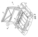
- Figure 1 shows a solid ink, or phase change, ink printer 10 that includes an outer housing having a top surface 12 and side surfaces 14.
- a user interface such as a front panel display screen 16 displays information concerning the status of the printer, and user instructions. are adjacent the user interface window, or may be at other locations on the printer.
- An ink jet printing mechanism (not shown) is contained inside the housing. Such a printing mechanism is described in United States Patent No. 5,805,191 , entitled Surface Application System, to Jones et al., and United States Patent No. 5,455,604 , entitled Ink Jet Printer Architecture and Method, to Adams et al.
- An ink feed system delivers ink to the printing mechanism.
- the ink feed system is contained under the top surface of the printer housing.
- the top surface of the housing includes a hinged ink access cover 20 that opens as shown in Figure 2 , to provide the user access to the ink feed system.
- the ink access cover 20 is attached to an ink load linkage element 22 so that when the printer ink access cover 20 is raised, the ink load linkage 22 slides and pivots to an ink load position.
- the interaction of the ink access cover and the ink load linkage element is described in United States Patent No. 5,861,903 for an Ink Feed System, issued January 19, 1999 to Crawford et al., though with some differences noted below.
- opening the ink access cover reveals a key plate 26 having keyed openings 24.
- Each keyed opening 24A, 24B, 24C, 24D provides access to an insertion end of one of several individual feed channels 28A, 28B, 28C, 28D of the solid ink feed system (see Figures 2 and 3 ).
- Each longitudinal feed channel 28 delivers ink sticks 30 of one particular color to a corresponding melt plate 32.
- Each feed channel has a longitudinal feed direction from the insertion end of the feed channel to the melt end of the feed channel.
- the melt end of the feed channel is adjacent the melt plate.
- the melt plate melts the solid ink stick into a liquid form.
- the melted ink drips through a gap 33 between the melt end of the feed channel and the melt plate, and into a liquid ink reservoir (not shown).
- the feed channels 28 have a longitudinal dimension from the insertion end to the melt end, and a lateral dimension, substantially perpendicular to the longitudinal dimension.
- Each feed channel in the particular embodiment illustrated includes a push block 34 driven by a driving force or element, such as a constant force spring 36, to push the individual ink sticks along the length of the longitudinal feed channel toward the melt plates 32 that are at the melt end of each feed channel.
- the tension of the constant force spring 36 drives the push block toward the melt end of the feed channel.
- the ink load linkage 22 is coupled to a yoke 38, which is attached to the constant force spring 36 mounted in the push block 34. The attachment to the ink load linkage 22 pulls the push block 34 toward the insertion end of the feed channel when the ink access cover is raised to reveal the key plate 26.
- the constant force spring 36 can be a flat spring with its face oriented along a substantially vertical axis.
- Figure 4 is a cross-sectional view of the set of feed channels 28A, 28B, 28C, 28D forming the feed chute of the ink delivery system.
- a color printer typically uses four colors of ink (yellow, cyan, magenta, and black).
- Ink sticks 30 of each color are delivered through a corresponding individual one of the feed channels 28A, 28B, 28C, 28D.
- the operator of the printer exercises cares to avoid inserting ink sticks of one color into a feed channel for a different color.
- Ink sticks may be so saturated with color dye that it may be difficult for a printer user to tell by color alone which color is which. Cyan, magenta, and black ink sticks in particular can be difficult to distinguish visually based on color appearance.
- the key plate 26 has keyed openings 24 to aid the printer user in ensuring that only ink sticks of the proper color are inserted into each feed channel.
- the intersections of the bottom surface 52 and the lateral side surfaces 56 of the ink stick body form lateral edges 58 of the bottom surface.
- the side surfaces 56 of the illustrated embodiment are stepped or tapered so that the upper portion of the ink stick body is slightly wider than the lower portion.
- the side surfaces 56 may also be substantially vertical, so that the upper and lower portions of the ink stick body are of substantially equal dimensions.
- the ink stick is illustrated without the key shapes on the lateral sides that correspond to the key plate openings 24 through the key plate 26, to simplify the illustration.
- the ink stick has a lateral center of gravity 63 between the two lateral sides 56 of the ink stick body.
- the weight distribution of the ink stick body is substantially uniform (not including protruding key elements), and the ink stick body is substantially symmetrical about its lateral center (not including protruding key elements), so that the lateral center of gravity 63 is approximately at the midpoint between the lateral sides 56 of the ink stick body (not including protruding key elements).
- the ink stick body has a vertical center of gravity 64 that is substantially midway between the top surface 54 of the ink stick body and the bottom surface 52 of the ink stick body.
- FIG. 6 shows a cross sectional view of a particular embodiment of the longitudinal feed channel 28 of the solid ink feed system.
- the feed channel includes a feed channel guide rail 40 positioned in a lower portion of the feed channel.
- This feed channel guide rail 40 provides feed system guide means for guiding the ink stick 30 in the feed channel.
- the first ink stick guide element 66 interacts with a first portion of the feed channel, and in particular the feed channel guide rail 40, to guide the ink stick along the feed channel 28.
- the feed channel guide rail 40 of the solid ink feed system and the first guide element 66 formed in the ink stick body are compatible with one another, and for example, have complementary shapes. The complementary shapes allow the lower guide element 66 of the ink stick body to slidingly engage the feed channel guide rail 40 of the ink stick feed channel 28.
- Key element shapes in the lateral side surfaces 56 of the ink stick body may tend to affect the orientation of the ink stick body as the ink stick moves along the feed channel.
- the interaction of the guide element 66 and the guide rail 40 counteracts that tendency, and maintains the correct orientation of the ink stick in the feed channel.
- the cooperative action of the ink stick guide element 66 and the feed channel guide rail 40 also reduce the "steering" effect the push block 34 acting on the trailing end surface of the ink stick in the feed channel 28.
- laterally offset pressure by the ink block is of lesser concern, and maintaining a perfect lateral balance of the force exerted by the push block on the ink stick is less critical than with certain other designs.
- Figures 7 through 18 show ink sticks having alternative shapes for the ink stick guide element.
- the bottom surface of the ink stick body need not be horizontal.
- the bottom surface 152 of the ink stick 130 is angled diagonally, and the ink stick guide element 166 is formed by the angular intersection of the bottom surface 152 with the lateral side surface 56 of the ink stick body.
- the printer feed system includes a feed channel guide rail 140 that has a shape complementary to the shape of the ink stick guide element 166 so that the ink stick guide element slidingly engages the feed channel guide rail.
- the second, upper guide element 68 of the ink stick slidingly engages the second, upper feed channel guide rail 48.
- the upper feed channel guide rail 48 is illustrated as formed as part of the feed channel frame. However, as noted above, the upper feed channel guide rail 48 can also be formed as part of the key plate 26.
- Figure 8 includes both a second lower ink stick guide element 267 interacting with a second lower feed channel guide rail 248 and an upper ink stick guide element 68 interacting with an upper feed channel guide rail 48, in most uses only one of those interactions is needed to guide the ink stick along the feed channel.
- the ink stick of Figure 8 need not use the second lower guide element 267, using only the upper guide element 68 to balance the interaction between the lower guide element 266 and the feed channel guide rail.
- substantially the only contact between the lower portion of the ink stick and the feed channel is the contact between the lower guide element 266 and the single feed channel guide rail 240 in the feed channel.
- the two lower ink stick guide elements 266, 267 each interact with the lower feed channel guide rails 240, 248, and the upper guide rail 48 is eliminated.
- Figure 9 illustrates an ink stick embodiment in which the lower guide element 366 is an angled, rather than curved, protrusion from the bottom surface 352 of the ink stick body.
- the feed channel for receiving such an ink stick includes a lower feed channel guide rail that has a compatible or complementary shape for receiving the angled lower guide element 366.
- the upper ink stick guide element 68 slidingly engages an upper guide rail in the feed channel.
- Figure 10 illustrates an ink stick embodiment that includes two angled lower guide elements 466, 467. Such an ink stick fits into a feed channel having correspondingly shaped lower feed channel guide rails (not shown). The overall structure of such a feed channel is similar to that shown in Figure 8 , although with angular lower feed channel guide rails.
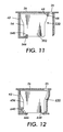
- Figure 11 shows an ink stick embodiment 530 in which the laterally offset lower ink stick guide element 566 is recessed into the bottom surface 552 of the ink stick body.
- the feed channel guide rail 540 in the feed channel for such an ink stick is raised, with a shape complementary to the shape of the recessed ink stick guide element 466, to slidingly engage the recessed ink stick guide element.
- a second feed channel guide rail 48 engages a different portion of the ink stick body to balance the ink stick in the feed channel.
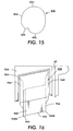
- Figure 16 shows an embodiment of the ink stick 930 in which the end surfaces 960 of the ink stick body are substantially flat, but not perpendicular to the lateral side surfaces 956. Thus, the bottom and top surfaces 952, 954 of the ink stick are not rectangular.
- the ink stick is illustrated as it is inserted through a correspondingly shaped key plate opening 924 in a printer key plate 926.
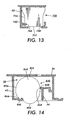
- Figure 17 shows an embodiment of the ink stick 1030 in which the ink stick has a substantially cylindrical shape.
- This embodiment illustrates that the ends 1060 of the ink stick body and the sides 1056 do not need to meet at a corner of the ink stick body.
- the first ink stick guide element 1066 laterally offset from the lateral center of gravity 1062 of the primary portion of the ink stick body, extends linearly along a segment of the bottom 1052 of the ink stick body sufficient to permit the ink stick guide element 1066 to properly guide the ink stick along a feed channel guide rail in the feed channel (not shown).
- a portion of the outer surface of the side 1056 on the opposite side of the lateral center of gravity forms a second ink stick guide element 1068.
- the second ink stick guide element slidingly engages a second feed channel guide rail (not shown) in the ink feed channel of the printer.
- the protrusion need not necessarily extend along the entire length of the ink stick body from the leading end surface to the trailing end surface.
- the protruding guide element may be formed in one or more segments, each of which extends along only a portion of the length of the ink stick body.
- a guide element formed along the entire length of the ink stick body, or at least segments formed at or near the leading (front) end surface, and at or near the trailing (rear) end surface of the ink stick body provide improved leverage for maintaining the proper orientation of the ink stick In the feed channel of the solid ink feed system.
- a method of loading an ink stick into a solid ink feed system includes inserting the ink stick through the appropriately shaped keyed opening 24, and into the insertion end of the longitudinal feed channel, as seen in Figures 2 and 3 .
- the first, lower ink stick guide element 66 is aligned with the feed channel guide rail 40 in the ink stick feed channel (see Figure 5 ).
- the ink stick is placed in the channel with the ink stick guide element 66 on the feed channel guide rail 40 so that the contact between the ink stick guide element and the feed channel guide rail is substantially the only contact between the bottom surface of the ink stick and the feed system.
Landscapes
- Physics & Mathematics (AREA)
- General Physics & Mathematics (AREA)
- Ink Jet (AREA)
- Particle Formation And Scattering Control In Inkjet Printers (AREA)
Applications Claiming Priority (2)
| Application Number | Priority Date | Filing Date | Title |
|---|---|---|---|
| US135051 | 2002-04-29 | ||
| US10/135,051 US6840612B2 (en) | 2002-04-29 | 2002-04-29 | Guide for solid ink stick feed |
Publications (2)
| Publication Number | Publication Date |
|---|---|
| EP1359021A1 EP1359021A1 (en) | 2003-11-05 |
| EP1359021B1 true EP1359021B1 (en) | 2008-05-28 |
Family
ID=29215636
Family Applications (1)
| Application Number | Title | Priority Date | Filing Date |
|---|---|---|---|
| EP03008887A Expired - Lifetime EP1359021B1 (en) | 2002-04-29 | 2003-04-29 | Guide for solid ink stick feed |
Country Status (5)
| Country | Link |
|---|---|
| US (2) | US6840612B2 (enExample) |
| EP (1) | EP1359021B1 (enExample) |
| JP (1) | JP4365131B2 (enExample) |
| BR (1) | BR0301140B1 (enExample) |
| DE (1) | DE60321261D1 (enExample) |
Families Citing this family (32)
| Publication number | Priority date | Publication date | Assignee | Title |
|---|---|---|---|---|
| US6722764B2 (en) * | 2002-04-29 | 2004-04-20 | Xerox Corporation | Feed guidance and identification for ink stick |
| US6739713B2 (en) | 2002-04-29 | 2004-05-25 | Xerox Corporation | Guide for solid ink stick feed |
| US7503648B2 (en) | 2005-06-09 | 2009-03-17 | Xerox Corporation | Ink consumption determination |
| US7296882B2 (en) | 2005-06-09 | 2007-11-20 | Xerox Corporation | Ink jet printer performance adjustment |
| US7458669B2 (en) * | 2005-06-09 | 2008-12-02 | Xerox Corporation | Ink consumption determination |
| US7425061B2 (en) * | 2005-06-09 | 2008-09-16 | Xerox Corporation | Ink consumption determination |
| US7438402B2 (en) * | 2006-01-03 | 2008-10-21 | Xerox Corporation | Rolling ink stick |
| US7780283B2 (en) * | 2006-11-07 | 2010-08-24 | Xerox Corporation | Independent keying and guidance for solid ink sticks |
| US7810918B2 (en) * | 2006-11-07 | 2010-10-12 | Xerox Corporation | One way compatibility keying for solid ink sticks |
| US7854501B2 (en) * | 2006-11-07 | 2010-12-21 | Xerox Corporation | Common side insertion keying for phase change ink sticks |
| US7690775B2 (en) * | 2006-11-07 | 2010-04-06 | Xerox Corporation | Solid ink sticks with corner guides |
| US7794072B2 (en) * | 2006-11-21 | 2010-09-14 | Xerox Corporation | Guide for printer solid ink transport and method |
| US7798624B2 (en) * | 2006-11-21 | 2010-09-21 | Xerox Corporation | Transport system for solid ink in a printer |
| US7651210B2 (en) * | 2006-11-21 | 2010-01-26 | Xerox Corporation | Transport system for solid ink for cooperation with melt head in a printer |
| US7976144B2 (en) * | 2006-11-21 | 2011-07-12 | Xerox Corporation | System and method for delivering solid ink sticks to a melting device through a non-linear guide |
| US7883195B2 (en) * | 2006-11-21 | 2011-02-08 | Xerox Corporation | Solid ink stick features for printer ink transport and method |
| US7753511B2 (en) * | 2006-11-28 | 2010-07-13 | Xerox Corporation | Lateral anti-skewing solution for solid ink |
| US7726797B2 (en) * | 2006-11-28 | 2010-06-01 | Xerox Corporation | Intermediate side slot vertical ink constraint with offset support |
| US7762655B2 (en) * | 2006-12-11 | 2010-07-27 | Xerox Corporation | Printer ink delivery system |
| US7878636B2 (en) * | 2006-12-12 | 2011-02-01 | Xerox Corporation | Solid ink stick chute for printer solid ink transport with mating solid ink stick chute |
| US7726798B2 (en) | 2006-12-15 | 2010-06-01 | Xerox Corporation | Printer solid ink transport and method |
| US7722177B2 (en) * | 2006-12-22 | 2010-05-25 | Xerox Corporation | System for loading ink sticks configured for lateral anti-skewing |
| US7798626B2 (en) * | 2007-02-28 | 2010-09-21 | Xerox Corporation | System for loading and feeding solid ink sticks to an ink melter in a phase change ink printer |
| US7909445B2 (en) * | 2007-09-11 | 2011-03-22 | Xerox Corporation | Solid ink stick delivery system with static constraints, strategic barriers and breakage controls |
| US7824027B2 (en) * | 2007-09-11 | 2010-11-02 | Xerox Corporation | Solid ink stick with anti jam edge bevel |
| US7976118B2 (en) | 2007-10-22 | 2011-07-12 | Xerox Corporation | Transport system for providing a continuous supply of solid ink to a melting assembly in a printer |
| US7883196B2 (en) | 2007-12-21 | 2011-02-08 | Xerox Corporation | System for delivering solid ink through a feed channel having non-linear sections |
| US7887173B2 (en) | 2008-01-18 | 2011-02-15 | Xerox Corporation | Transport system having multiple moving forces for solid ink delivery in a printer |
| US8240830B2 (en) | 2010-03-10 | 2012-08-14 | Xerox Corporation | No spill, feed controlled removable container for delivering pelletized substances |
| US8814336B2 (en) | 2011-12-22 | 2014-08-26 | Xerox Corporation | Solid ink stick configuration |
| US8727478B2 (en) | 2012-10-17 | 2014-05-20 | Xerox Corporation | Ink loader having optical sensors to identify solid ink sticks |
| US8777386B2 (en) | 2012-10-17 | 2014-07-15 | Xerox Corporation | Solid ink stick having identical identifying features on a plurality of edges |
Family Cites Families (12)
| Publication number | Priority date | Publication date | Assignee | Title |
|---|---|---|---|---|
| US5455604A (en) | 1991-04-29 | 1995-10-03 | Tektronix, Inc. | Ink jet printer architecture and method |
| US5223860A (en) * | 1991-06-17 | 1993-06-29 | Tektronix, Inc. | Apparatus for supplying phase change ink to an ink jet printer |
| US5805191A (en) | 1992-11-25 | 1998-09-08 | Tektronix, Inc. | Intermediate transfer surface application system |
| US5861903A (en) | 1996-03-07 | 1999-01-19 | Tektronix, Inc. | Ink feed system |
| US5734402A (en) | 1996-03-07 | 1998-03-31 | Tekronix, Inc. | Solid ink stick feed system |
| US6053608A (en) * | 1996-07-24 | 2000-04-25 | Brother Kogyo Kabushiki Kaisha | Ink pellet with step configuration including slidable bearing surfaces |
| USD407112S (en) * | 1998-01-22 | 1999-03-23 | Textronix, Inc. | Solid ink stick for a color printer |
| JPH11254699A (ja) | 1998-03-09 | 1999-09-21 | Brother Ind Ltd | 画像記録装置 |
| US6719419B2 (en) * | 2002-04-29 | 2004-04-13 | Xerox Corporation | Feed channel keying for solid ink stick feed |
| US6722764B2 (en) * | 2002-04-29 | 2004-04-20 | Xerox Corporation | Feed guidance and identification for ink stick |
| US6840613B2 (en) * | 2002-04-29 | 2005-01-11 | Xerox Corporation | Guide for solid ink stick feed |
| US6739713B2 (en) * | 2002-04-29 | 2004-05-25 | Xerox Corporation | Guide for solid ink stick feed |
-
2002
- 2002-04-29 US US10/135,051 patent/US6840612B2/en not_active Expired - Lifetime
-
2003
- 2003-04-28 BR BRPI0301140-2A patent/BR0301140B1/pt not_active IP Right Cessation
- 2003-04-29 EP EP03008887A patent/EP1359021B1/en not_active Expired - Lifetime
- 2003-04-29 DE DE60321261T patent/DE60321261D1/de not_active Expired - Lifetime
- 2003-04-30 JP JP2003125696A patent/JP4365131B2/ja not_active Expired - Fee Related
-
2004
- 2004-11-01 US US10/980,106 patent/US7066589B2/en not_active Expired - Fee Related
Also Published As
| Publication number | Publication date |
|---|---|
| US7066589B2 (en) | 2006-06-27 |
| JP4365131B2 (ja) | 2009-11-18 |
| US20050062820A1 (en) | 2005-03-24 |
| BR0301140B1 (pt) | 2011-10-04 |
| JP2003320682A (ja) | 2003-11-11 |
| EP1359021A1 (en) | 2003-11-05 |
| DE60321261D1 (de) | 2008-07-10 |
| BR0301140A (pt) | 2004-08-17 |
| US6840612B2 (en) | 2005-01-11 |
| US20030202067A1 (en) | 2003-10-30 |
Similar Documents
| Publication | Publication Date | Title |
|---|---|---|
| EP1359021B1 (en) | Guide for solid ink stick feed | |
| EP1359022B1 (en) | Guide for solid ink stick feed | |
| EP1359016B1 (en) | Guide for solid ink stick feed | |
| EP1359019B1 (en) | Feed channel keying for solid ink stick feed | |
| EP1366915B1 (en) | Load and feed apparatus for solid ink | |
| EP1369243B1 (en) | Channel keying for solid ink stick insertion | |
| EP1366913B1 (en) | Load and feed apparatus for solid ink | |
| CA2426228C (en) | Solid ink stick set identification | |
| EP1359014B1 (en) | Alignment feature for solid ink stick | |
| US6986570B2 (en) | Feed guidance and identification for ink stick | |
| EP1366909B1 (en) | Keying feature for solid ink stick | |
| EP1359017A1 (en) | Multiple portion solid ink stick | |
| EP1366912A2 (en) | Load and feed apparatus for solid ink | |
| EP1552941A2 (en) | Guide for solid ink stick feed | |
| EP1366917A2 (en) | Load and feed apparatus for solid ink | |
| EP1366911B1 (en) | Load and feed apparatus for solid ink | |
| US7753511B2 (en) | Lateral anti-skewing solution for solid ink | |
| US7722177B2 (en) | System for loading ink sticks configured for lateral anti-skewing | |
| US7726797B2 (en) | Intermediate side slot vertical ink constraint with offset support |
Legal Events
| Date | Code | Title | Description |
|---|---|---|---|
| PUAI | Public reference made under article 153(3) epc to a published international application that has entered the european phase |
Free format text: ORIGINAL CODE: 0009012 |
|
| AK | Designated contracting states |
Kind code of ref document: A1 Designated state(s): AT BE BG CH CY CZ DE DK EE ES FI FR GB GR HU IE IT LI LU MC NL PT RO SE SI SK TR |
|
| AX | Request for extension of the european patent |
Extension state: AL LT LV MK |
|
| 17P | Request for examination filed |
Effective date: 20040506 |
|
| AKX | Designation fees paid |
Designated state(s): DE FR GB |
|
| 17Q | First examination report despatched |
Effective date: 20041018 |
|
| GRAP | Despatch of communication of intention to grant a patent |
Free format text: ORIGINAL CODE: EPIDOSNIGR1 |
|
| GRAS | Grant fee paid |
Free format text: ORIGINAL CODE: EPIDOSNIGR3 |
|
| GRAC | Information related to communication of intention to grant a patent modified |
Free format text: ORIGINAL CODE: EPIDOSCIGR1 |
|
| GRAA | (expected) grant |
Free format text: ORIGINAL CODE: 0009210 |
|
| AK | Designated contracting states |
Kind code of ref document: B1 Designated state(s): DE FR GB |
|
| REG | Reference to a national code |
Ref country code: GB Ref legal event code: FG4D |
|
| REF | Corresponds to: |
Ref document number: 60321261 Country of ref document: DE Date of ref document: 20080710 Kind code of ref document: P |
|
| PLBE | No opposition filed within time limit |
Free format text: ORIGINAL CODE: 0009261 |
|
| STAA | Information on the status of an ep patent application or granted ep patent |
Free format text: STATUS: NO OPPOSITION FILED WITHIN TIME LIMIT |
|
| 26N | No opposition filed |
Effective date: 20090303 |
|
| REG | Reference to a national code |
Ref country code: FR Ref legal event code: PLFP Year of fee payment: 14 |
|
| REG | Reference to a national code |
Ref country code: FR Ref legal event code: PLFP Year of fee payment: 15 |
|
| PGFP | Annual fee paid to national office [announced via postgrant information from national office to epo] |
Ref country code: FR Payment date: 20170322 Year of fee payment: 15 |
|
| PGFP | Annual fee paid to national office [announced via postgrant information from national office to epo] |
Ref country code: GB Payment date: 20170324 Year of fee payment: 15 |
|
| PGFP | Annual fee paid to national office [announced via postgrant information from national office to epo] |
Ref country code: DE Payment date: 20170321 Year of fee payment: 15 |
|
| REG | Reference to a national code |
Ref country code: DE Ref legal event code: R119 Ref document number: 60321261 Country of ref document: DE |
|
| GBPC | Gb: european patent ceased through non-payment of renewal fee |
Effective date: 20180429 |
|
| PG25 | Lapsed in a contracting state [announced via postgrant information from national office to epo] |
Ref country code: DE Free format text: LAPSE BECAUSE OF NON-PAYMENT OF DUE FEES Effective date: 20181101 |
|
| PG25 | Lapsed in a contracting state [announced via postgrant information from national office to epo] |
Ref country code: GB Free format text: LAPSE BECAUSE OF NON-PAYMENT OF DUE FEES Effective date: 20180429 |
|
| PG25 | Lapsed in a contracting state [announced via postgrant information from national office to epo] |
Ref country code: FR Free format text: LAPSE BECAUSE OF NON-PAYMENT OF DUE FEES Effective date: 20180430 |