EP1357874B2 - Formeinsatz - Google Patents
Formeinsatz Download PDFInfo
- Publication number
- EP1357874B2 EP1357874B2 EP01985613.7A EP01985613A EP1357874B2 EP 1357874 B2 EP1357874 B2 EP 1357874B2 EP 01985613 A EP01985613 A EP 01985613A EP 1357874 B2 EP1357874 B2 EP 1357874B2
- Authority
- EP
- European Patent Office
- Prior art keywords
- apertures
- particles
- receptacle
- forming
- aperture
- Prior art date
- Legal status (The legal status is an assumption and is not a legal conclusion. Google has not performed a legal analysis and makes no representation as to the accuracy of the status listed.)
- Expired - Lifetime
Links
- 239000000463 material Substances 0.000 claims description 76
- 239000002250 absorbent Substances 0.000 claims description 69
- 239000002245 particle Substances 0.000 claims description 52
- 230000002745 absorbent Effects 0.000 claims description 42
- 238000000034 method Methods 0.000 claims description 40
- 239000000758 substrate Substances 0.000 claims description 27
- 239000011236 particulate material Substances 0.000 claims description 16
- 239000011159 matrix material Substances 0.000 claims description 11
- 238000001259 photo etching Methods 0.000 claims description 5
- 239000002131 composite material Substances 0.000 claims description 3
- 239000011162 core material Substances 0.000 description 21
- 239000000835 fiber Substances 0.000 description 14
- 230000008569 process Effects 0.000 description 9
- 239000002243 precursor Substances 0.000 description 5
- 230000007246 mechanism Effects 0.000 description 4
- 239000000853 adhesive Substances 0.000 description 3
- 230000001070 adhesive effect Effects 0.000 description 3
- PXHVJJICTQNCMI-UHFFFAOYSA-N Nickel Chemical compound [Ni] PXHVJJICTQNCMI-UHFFFAOYSA-N 0.000 description 2
- 229920001131 Pulp (paper) Polymers 0.000 description 2
- VYPSYNLAJGMNEJ-UHFFFAOYSA-N Silicium dioxide Chemical compound O=[Si]=O VYPSYNLAJGMNEJ-UHFFFAOYSA-N 0.000 description 2
- 230000004075 alteration Effects 0.000 description 2
- 229910052782 aluminium Inorganic materials 0.000 description 2
- XAGFODPZIPBFFR-UHFFFAOYSA-N aluminium Chemical compound [Al] XAGFODPZIPBFFR-UHFFFAOYSA-N 0.000 description 2
- 238000004364 calculation method Methods 0.000 description 2
- 238000001311 chemical methods and process Methods 0.000 description 2
- 238000005520 cutting process Methods 0.000 description 2
- 238000009826 distribution Methods 0.000 description 2
- 238000004519 manufacturing process Methods 0.000 description 2
- 229910052751 metal Inorganic materials 0.000 description 2
- 239000002184 metal Substances 0.000 description 2
- 150000002739 metals Chemical class 0.000 description 2
- 239000000203 mixture Substances 0.000 description 2
- 230000004048 modification Effects 0.000 description 2
- 238000012986 modification Methods 0.000 description 2
- 231100000252 nontoxic Toxicity 0.000 description 2
- 230000003000 nontoxic effect Effects 0.000 description 2
- 229910001220 stainless steel Inorganic materials 0.000 description 2
- 239000010935 stainless steel Substances 0.000 description 2
- XLYOFNOQVPJJNP-UHFFFAOYSA-N water Substances O XLYOFNOQVPJJNP-UHFFFAOYSA-N 0.000 description 2
- 241000894006 Bacteria Species 0.000 description 1
- RYGMFSIKBFXOCR-UHFFFAOYSA-N Copper Chemical compound [Cu] RYGMFSIKBFXOCR-UHFFFAOYSA-N 0.000 description 1
- 229910000831 Steel Inorganic materials 0.000 description 1
- 239000004809 Teflon Substances 0.000 description 1
- 229920006362 Teflon® Polymers 0.000 description 1
- RTAQQCXQSZGOHL-UHFFFAOYSA-N Titanium Chemical compound [Ti] RTAQQCXQSZGOHL-UHFFFAOYSA-N 0.000 description 1
- 238000005411 Van der Waals force Methods 0.000 description 1
- 238000009825 accumulation Methods 0.000 description 1
- 238000003491 array Methods 0.000 description 1
- 238000005452 bending Methods 0.000 description 1
- 230000008901 benefit Effects 0.000 description 1
- 230000015572 biosynthetic process Effects 0.000 description 1
- -1 but not limited to Substances 0.000 description 1
- 239000000919 ceramic Substances 0.000 description 1
- 238000003486 chemical etching Methods 0.000 description 1
- 239000011248 coating agent Substances 0.000 description 1
- 238000000576 coating method Methods 0.000 description 1
- 238000010276 construction Methods 0.000 description 1
- 238000011109 contamination Methods 0.000 description 1
- 229910052802 copper Inorganic materials 0.000 description 1
- 239000010949 copper Substances 0.000 description 1
- 229920006037 cross link polymer Polymers 0.000 description 1
- 230000001419 dependent effect Effects 0.000 description 1
- 238000005553 drilling Methods 0.000 description 1
- 239000000499 gel Substances 0.000 description 1
- 230000005484 gravity Effects 0.000 description 1
- 239000011121 hardwood Substances 0.000 description 1
- 229910052739 hydrogen Inorganic materials 0.000 description 1
- 239000001257 hydrogen Substances 0.000 description 1
- 230000002209 hydrophobic effect Effects 0.000 description 1
- 229910010272 inorganic material Inorganic materials 0.000 description 1
- 239000011147 inorganic material Substances 0.000 description 1
- 239000007788 liquid Substances 0.000 description 1
- 238000005259 measurement Methods 0.000 description 1
- 229920005615 natural polymer Polymers 0.000 description 1
- 229910052759 nickel Inorganic materials 0.000 description 1
- 150000002894 organic compounds Chemical class 0.000 description 1
- 239000004033 plastic Substances 0.000 description 1
- 229920003023 plastic Polymers 0.000 description 1
- 239000011148 porous material Substances 0.000 description 1
- 238000004080 punching Methods 0.000 description 1
- 230000008707 rearrangement Effects 0.000 description 1
- 230000009467 reduction Effects 0.000 description 1
- 239000000377 silicon dioxide Substances 0.000 description 1
- 238000005549 size reduction Methods 0.000 description 1
- 239000011122 softwood Substances 0.000 description 1
- 239000002195 soluble material Substances 0.000 description 1
- 239000010959 steel Substances 0.000 description 1
- 239000000126 substance Substances 0.000 description 1
- 239000010936 titanium Substances 0.000 description 1
- 229910052719 titanium Inorganic materials 0.000 description 1
- 238000011282 treatment Methods 0.000 description 1
- WFKWXMTUELFFGS-UHFFFAOYSA-N tungsten Chemical compound [W] WFKWXMTUELFFGS-UHFFFAOYSA-N 0.000 description 1
- 229910052721 tungsten Inorganic materials 0.000 description 1
- 239000010937 tungsten Substances 0.000 description 1
- 239000011800 void material Substances 0.000 description 1
- 238000009941 weaving Methods 0.000 description 1
- 238000003466 welding Methods 0.000 description 1
Images


Classifications
-
- A—HUMAN NECESSITIES
- A61—MEDICAL OR VETERINARY SCIENCE; HYGIENE
- A61F—FILTERS IMPLANTABLE INTO BLOOD VESSELS; PROSTHESES; DEVICES PROVIDING PATENCY TO, OR PREVENTING COLLAPSING OF, TUBULAR STRUCTURES OF THE BODY, e.g. STENTS; ORTHOPAEDIC, NURSING OR CONTRACEPTIVE DEVICES; FOMENTATION; TREATMENT OR PROTECTION OF EYES OR EARS; BANDAGES, DRESSINGS OR ABSORBENT PADS; FIRST-AID KITS
- A61F13/00—Bandages or dressings; Absorbent pads
- A61F13/15—Absorbent pads, e.g. sanitary towels, swabs or tampons for external or internal application to the body; Supporting or fastening means therefor; Tampon applicators
- A61F13/15577—Apparatus or processes for manufacturing
- A61F13/15617—Making absorbent pads from fibres or pulverulent material with or without treatment of the fibres
- A61F13/15626—Making fibrous pads without outer layers
Definitions
- the present invention relates to forming receptacles and methods for receiving particulate material thereon, and thereby fabricating particulate congregates for use as absorbent cores in personal care absorbent articles. More particularly, one of the contemplated applications for the present invention is in a forming drum comprising a plurality of forming receptacles designed and configured to form particulate congregates for use as absorbent cores in personal care absorbent articles.
- the holes arranged in a rectangular pattern does not facilitate optimum formation of personal care absorbent articles because the fraction of the open area represented by the holes in the screen or plate, is so low as to impede desired rates of air flow through the screen or plate. There is a need for a more porous media.
- the inventors herein have discovered that rectangular arrangement of the forming media holes is less efficient than improved media of the invention.
- the hole size of the conventional screens is nearly twice the size of an average particle of super-absorbent material (SAM) as may typically be used in fabricating personal care absorbent articles. SAM lost by passing through the e.g. screen or perforated plate results in significant in-process loss that must be compensated for by overfeeding the SAM system.
- SAM super-absorbent material
- the conventional hole arrangement is also subject to plugging, caused by a single particle, or multiple particles, of SAM getting lodged into a single perforation or hole. Compressed air is periodically used to dislodge as many of the plugged holes as possible. Over the course of a few weeks, screens become significantly plugged, the machine must be shut down, and the screens must be removed and steam cleaned, thus significantly hindering the quality and rate of operation for production of significant elements of personal care absorbent articles.
- the problem for the present invention is thus to provide forming media, as well as methods, for receiving particulate material thereon, and thereby fabricating particulate congregates for use as absorbent cores in personal care absorbent articles, whereby the holes in the forming media are not arranged in a rectangular array, and whereby the configurations of individual ones of the holes in the forming media discourage plugging of the forming media.
- the invention provides a forming receptacle as claimed in claim 1.
- the forming receptacle is adapted and configured to receive particulate material thereon, including super-absorbent particles, for thereby fabricating particulate congregates for use as absorbent cores in personal care absorbent articles.
- the forming receptacle comprises sheet material defining a bottom wall of the receptacle, and a side wall of the receptacle extending upwardly from the bottom wall thereby to define a particulate-receiving cavity in the receptacle.
- the bottom wall and the side wall have, in combination, a first major surface disposed toward the cavity, an opposing second major surface disposed away from the cavity, and a thickness between the first and second major surfaces.
- the forming receptacle also comprises an array of apertures extending through the bottom wall, and optionally through the side wall, and connecting the first and second major surfaces, and further comprises a matrix of the sheet material between respective ones of the apertures and defining outer perimeters of respective ones of the apertures.
- the bottom wall and the side wall in conjunction, comprise a particulate receiving cavity having a depth of at least about 0.001 inch to about 2.00 inches (0.003 to about 5.08 cm).
- the aperture walls define cross-sectional areas of such apertures along the thickness of the sheet material, including a first locus defining a smallest cross-sectional area, and a second locus defining a relatively larger cross-sectional area displaced from the smallest cross-sectional area and disposed, from the first locus, toward the second major surface of the sheet material.
- the smallest cross-sectional area can be displaced from and between both of the first and second surfaces.
- Thickness of the sheet material is preferably about 0.003 inch to about 0.030 inch (0.008 to about 0.076 cm), and more preferably about 0.005 inch to about 0.015 inch (0.013 to about 0.038 cm).
- Length of the receptacle is preferably about 10 inches to about 30 inches (25 to about 76 cm), more preferably about 12 inches to about 24 inches (30 to about 61 cm). Structures of the apertures can reflect photochemical machining.
- the invention provides a method for forming a congregate of particulate material for use as an absorbent core in an absorbent article as claimed in claim 4.
- the particulate material comprises generally particles, optionally spherically-shaped particles, of super-absorbent material.
- the method comprises conveying the particulate material in a gaseous carrier toward a forming receptacle.
- the forming receptacle comprises sheet material defining a bottom wall of the receptacle.
- the sheet material also defines a side wall of the receptacle extending upwardly from the bottom wall.
- the bottom wall and the side wall in combination, define a particulate-receiving cavity in the receptacle.
- the bottom wall and the side wall have, in combination, a first major surface disposed toward the cavity, an opposing second major surface disposed away from the cavity, and a thickness between the first and second major surfaces.
- An array of apertures extend through the bottom wall and define passage ways between the first and second major surfaces.
- the passage ways are defined by aperture walls which taper generally outwardly from central axes of the respective passage ways, and from proximate the first major surface toward the second major surface.
- the passage ways tend to generally progressively expand in cross-sectional area as one progresses toward the second major surface, and projected areas of the particles of the super-absorbent material are generally larger than projected areas of the apertures.
- the method further comprises receiving and collecting particles of the particulate material in the cavity and thereby forming the congregate while generally not conveying particles of the super-absorbent material into the passage ways.
- Undersize particles of super-absorbent material which do enter respective ones of the passage ways tend to pass entirely through the passage ways and not become lodged in such passage ways because of being released to pass through such passage ways, by the generally progressively expanding cross-sections of such passage ways along the direction of travel of such particles.
- the projected area of a respective such aperture is defined by a relatively more constrictive throat zone of the respective passage way, the throat zone being disposed closer to the first major surface than to the second major surface.
- a projection of such throat zone is typically no more than 25 percent, preferably no more than 15 percent, smaller in cross-sectional area than a projection of the respective aperture at the first surface.
- a projection of the throat zone is substantially the same size in cross-sectional area as a projection of the respective aperture at the first surface.
- the method comprises receiving and collecting the particles of a such forming receptacle wherein the particles of super-absorbent material are generally oblong-shaped, having a length-to-width ratio of no more than 4/1.
- FIGURE 1 shows a forming receptacle 10 comprising a bottom wall 12 of receptacle 10, and side walls 14 of receptacle 10 extending upwardly from the bottom wall to a top edge 15 thereof.
- bottom wall 12 has a generally flat surface which meets side walls 14 of receptacle 10, side walls 14 extending upwardly to top edges 15 of side walls 14.
- bottom wall 12 in conjunction with side walls 14 define a particulate-receiving cavity 20 in the receptacle.
- Bottom wall 12 and side walls 14 have, in combination, a first major side or surface 16 disposed toward cavity 20, an opposing second major side or surface 18 disposed away from cavity 20.
- An array of apertures 22 extend through receptacle 10 and connect the first and second major surfaces.
- FIGURE 1 shows side walls 14 disposed in an angular relationship with bottom wall 12
- the invention contemplates various embodiments of forming receptacles having bottom and side walls meeting in singular arcuate relationships, as well as in multiple arcuate relationships.
- An arcuate meeting relationship between the bottom and side wall can comprise ones of inflections as well as a plurality of effective radii defining the curvature of the arcuate meeting relationship.
- bottom wall 12 and side walls 14 of receptacle 10 are illustrated in FIGURE 1 as having generally flat surfaces, some embodiments comprise one or both bottom wall 12 and side walls 14 having angled, curved, and/or arcuate surfaces.
- the forming receptacle comprises a length "L1", a width "W1", a depth "D5", and a thickness.
- the length of the receptacle can be about 10 inches to about 30 inches (25 to about 76 cm), and preferably, about 12 inches to about 24 inches (30 to about 61 cm).
- the length and width of the receptacle can depend upon the size of the e.g. absorbent articles into which respective absorbent cores are to be incorporated. Alternatively, the length and width of the receptacle depend upon the desired absorptive capabilities of the absorbent core portion of such corresponding absorbent article.
- Some embodiments contemplate a receptacle having one or both a length and width being greater or smaller than the dimensions of the desired absorbent core, e.g. as in continuous, uninterrupted production of absorbent core material which can be segmented later.
- particulate-receiving cavity 20 extends across substantially the entirety of one or both the length and width of forming receptacle 10. In other embodiments, particulate-receiving cavity 20 extends across a portion of one or both the length and width of forming receptacle 10. Embodiments reflect a depth D5 of at least about 0.001 inch to about 2.00 inches (0.003 to about 5.08 cm). In all embodiments, the depth of the forming receptacle is generally dependent upon the desired absorptive capabilities of the resultant absorbent core portion of such corresponding absorbent article.
- the thickness of the apertured sheet material of forming receptacle 10 can be about 0.003 inch to about 0.030 inch (0.098 to about 0.983 cm), and preferably, about 0.005 inch to about 0.015 inch (0.013 to about 0.038 cm).
- Forming receptacle 20 preferably comprises stainless steel, but can also comprise a variety of materials including, but not limited to, metals such as nickel, aluminum, tungsten, titanium, and copper. The materials listed are preferred because the materials are formable, economical, and also non-toxic. Other materials, especially metals, which are formable, as well as economical and non-toxic are contemplated as forming receptacle materials. Other materials and substrates capable being formed and comprising tapered holes such as ceramics and plastics are also contemplated.
- FIGURE 2 shows an enlarged example one embodiment of an aperture 22 of the forming receptacle illustrated in FIGURE 1 .
- apertures 22 generally comprise aperture walls 24 extending from first major surface 16 to second major surface 18.
- the respective aperture walls 24 taper generally outwardly away from a central axis 26 of respective aperture 24, and generally from first major surface 16 toward second major surface 18.
- Thickness "T” of the material represents the distance between top surface 16 and bottom surface 18.
- the thickness of the material can be about 0.003 inch to about 0.030 inch (0.098 to about 0.983 cm), and preferably, about 0.005 inch to about 0.015 inch (0.013 to about 0.038 cm).
- Aperture walls define cross-sectional areas of such apertures along the thickness of the substrate or sheet material, and include a first locus 25 defining a smallest cross-sectional area, and second loci defining a relatively larger cross-sectional area displaced from the smallest cross-sectional area and disposed, from the first locus, toward second major surface 18 of the substrate or sheet material.
- the portion of aperture wall 24 disposed between first locus 25 and surface 16 defines an upper section 23 of aperture wall 24.
- the portion of aperture wall 24 disposed between first locus 25 and surface 18 defines a lower section 27 of aperture wall 24.
- the smallest cross-sectional area is displaced from and between both of the first and second surfaces in throat zone 28.
- the apertures define cross-sectional areas proximate the first and second surfaces in which the cross-sectional area proximate second surface 18 is greater than the cross-sectional area proximate first surface 16.
- FIGURES 3A, 3B, and 3C show enlarged cross-sectional views of three illustrative embodiments of forming receptacle 10.
- thickness "T" of the material represents the distance between top surface 16 and bottom surface 18.
- a central aperture axis generally passes through the center of each aperture.
- FIGURE 3A illustrates apertures 22 comprising aperture walls 24 which extend from loci 25 or throats of smallest projected cross-section 28 at and/or adjacent first surface 16 and taper generally outwardly from the inner loci to second major surface 18.
- the open areas defined by the respective apertures at second major surface 18 are greater than open areas defined by respective ones of such apertures 22 at first major surface 16.
- FIGURE 3B illustrates apertures 22 comprising aperture walls 24 which extend generally perpendicular to first surface 16 from loci 25 adjacent first surface 16 to interior loci between first surface 16 and second surface 18, thus to define throats of smallest projected cross-sectional area 28.
- the interior loci are preferably closer to top surface 16 than bottom surface 18.
- Walls 24 then taper generally outwardly from the interior loci to second major surface 18.
- An upper section 23 of aperture wall 24 is defined by the portion of aperture wall 24 between throat area 28 and surface 16; similarly, a lower section 27 of aperture wall 24 is defined by the portion of aperture wall 24 between throat area 28 and surface 18.
- the open areas defined by respective apertures 22 at second major surface 18 are greater in cross-section than open areas defined by respective ones of such apertures 22 at first major surface 16.
- FIGURE 3C illustrates in cross-section a series of apertures 22 corresponding to aperture 22 as shown in FIGURE 2 .
- the apertures comprise aperture walls 24 which taper inwardly from first major surface 16 and toward second major surface 18. to an interior locus illustrated as throat zone 28. Walls 24 taper thence outwardly from throat zone 28 to second major surface 18, such that throat zone 28 defines a projected opening generally equal to or smaller in cross-sectional area than corresponding openings defined by the respective aperture at either of the first or second major surfaces.
- An upper section 23 of aperture wall 24 is defined by the portion of aperture wall 24 between throat area 28 and surface 16; similarly, a lower section 27 of aperture wall 24 is defined by the portion of aperture wall 24 between throat area 28 and surface 18.
- a projection of throat zone 28 is no more than 25 percent smaller in cross-sectional area than a projection of respective aperture 22 at first surface 16. In other embodiments, a projection of throat zone 28 is no more than 15 percent smaller in cross-sectional area than a projection of respective aperture 22 at first surface 16.
- An aperture comprising a cross-section at surface 16 which is more than 25 percent greater in cross-sectional area than the projection of throat zones can result in creating an upper section of aperture wall 24 that is large enough to cradle and lodge particles of super-absorbent material in the aperture.
- a projection of throat zone 28 is substantially the same size in cross-sectional area as a projection of respective aperture 22 at first surface 16.
- a respective aperture 22 defines an opening at first major surface 16.
- the opening generally has an open area corresponding to the area of a circle having a diameter of at least about 0.009 inch (0.02 cm), up to about 0.040 inch (0.10 cm), preferably, at least about 0.010 inch (0.025 cm), up to about 0.025 inch (0.064 cm), and more preferably, at least about 0.011 inch (0.028 cm), up to about 0.015 inch (0.038 cm).
- the relationship shown between respective ones of aperture walls and surface 16 is not angular but curved, wherein the curvature can comprise one or more effective radii.
- the matrix of sheet material at first major surface 16 generally has a minimum projected width between respective ones of the apertures "D3" of about 0.003 inch to about 0.015 inch (0.008 to about 0.038 cm), and preferably, about 0.005 inch to about 0.009 inch (0.013 to about 0.023 cm).
- aperture walls 24 of adjacent ones of the apertures 22 preferably intersect second major surface 18 in very close proximity to each other without intersecting each other, thereby defining nominal distances "D4" between the respective apertures at surface 18.
- the matrix of sheet material at second major surface 18 generally has a minimum width between respective ones of the apertures "D4" of about 0.0007 inch up to about 0.004 inch (0.002 to about 0.010 cm). preferably, about 0.0007 inch up to about 0.003 inch (0.002 to about 0.008 cm), and more preferably, about 0.001 inch up to about 0.002 inch (0.003 to about 0.005 cm).
- Apertures 24 can be formed in a sheet material precursor of forming receptacle 10 by a chemical etching process, such that structures of the apertures reflect photochemical machining, such as, e.g. a photo etch process or micro-etchTM process.
- photochemical machining such as, e.g. a photo etch process or micro-etchTM process.
- photo tooling is typically created to correspond to desired size of openings of a resultant forming receptacle precursor.
- a substrate or sheet material to be machined is coated with a photosensitive resist.
- One or both sides of the substrate or sheet material can be coated with the photosensitive resist.
- One or both sides of the coated substrate or sheet material are then exposed with a negative image of a desired forming receptacle precursor and developed.
- the substrate or sheet material is then chemically processed.
- Each side or surface of the substrate or sheet material is treated with the chemical process.
- the chemical process removes unprotected portions of the substrate or sheet material, thereby creating apertures, yet does not affect the portions coated with photosensitive resist, thereby forming the array of apertures illustrated e.g. in FIGURE 1 , in a forming receptacle precursor.
- the longer each side is treated with the chemical 1 process the more of the substrate or sheet material is removed from that respective side or surface.
- Separately treating each side of the substrate or sheet material allows for a variety aperture angles and orientations, and positionings of throat portion 28.
- the substrate or sheet material 1 is formed into a forming receptacle as in FIGURE 1 . capable of collecting congregates of particulate material.
- the major planar surfaces 16, 18 of the forming receptacle are free of burrs, crevices and rough edges, with corresponding reduction in tendency for entrapping particles or bacteria, thus reducing tendency for contamination related to such entrapments.
- apertures on respective forming receptacles do not have to comprise the same size or same shape as other apertures of the respective forming receptacle.
- some embodiments contemplate an arrays of apertures which do not comprise uniform configurations or arrangements throughout the forming receptacle.
- FIGURE 4 shows plan view of the substrate at top surface 16 of a preferred embodiment demonstrating the spacial relationship between apertures 22 and the surrounding matrix of sheet material. While FIGURE 4 shows an illustration of top surface 16 of embodiments shown in FIGURES 3A and 3B , a plan view of top surface 16 of the embodiment shown in FIGURE 3C would illustrate another concentric ring representing the tapered throat region of the apertures inside that of the circular opening formed by the intersection of the aperture walls and top surface 16.
- the section of sheet material shown in FIGURE 4 has an exemplary length "L2" and an exemplary width "W2". Length "L2" and width “W2" are shown for illustrative purposes only, and should not be construed as limiting.
- the matrix, of substrate or sheet material between respective ones of the apertures defines outer perimeters of respective ones of the apertures.
- a respective aperture 22 defines an opening at first major surface 16, the opening having an open area corresponding to the area of a circle having a diameter of at least about 0.009 inch (0.02 cm), up to about 0.040 inch (0.10 cm), preferably, at least about 0.010 inch (0.025 cm), up to about 0.025 inch (0.064 cm), and more preferably, at least about 0.011 inch (0.028 cm), up to about 0.015 inch (0.038 cm).
- the matrix of sheet material at first major surface 16 generally has a minimum projected width "D3" between respective ones of the apertures of about 0.003 inch to about 0.015 inch (0.008 to about 0.038 cm), and preferably about 0.005 inch to about 0.009 inch (0.013 to about 0.025 cm). It should be noted that "D3", as measured from projected area, is the measurement from throat-to-throat.
- the array of apertures shown in the preferred embodiment illustrated in FIGURE 4 is arranged in a series of parallel rows of apertures, wherein spacing between apertures in a given row is substantially constant from row to row.
- a row is defined as any series of apertures intersected by a straight line where the straight line intersects the center-point of origin of any two adjacent apertures.
- the distance "D1" between center points of adjacent apertures of a given row can be about 0.010 inch to about 0.050 inch (0.025 to about 0.127 cm), and preferably about 0.012 inch to about 0.020 inch (0.030 to about 0.051 cm).
- the distance between center points of adjacent apertures in adjacent rows "D2" can be about 0.008 inch to about 0.045 inch (0.020 to about 0.114 cm), and preferably, 0.010 inch to about 0.018 inch (0.025 to about 0.046 cm).
- the rows of apertures are displaced laterally with respect to each other such that adjacent apertures in adjacent rows define angles " ⁇ " of about 50 degrees to about 90 degrees with respect to an imaginary line extending parallel to the rows. In some preferred embodiments, the rows of apertures are displaced laterally with respect to each other such that adjacent apertures in adjacent rows define angles " ⁇ " of about 80 degrees to about 90 degrees with respect to an imaginary line extending parallel to the rows. In yet other preferred embodiments, the rows of apertures are displaced laterally with respect to each other such.that adjacent apertures in adjacent rows define angles " ⁇ " of about 50 degrees to about 70 degrees with respect to an imaginary line extending parallel to the rows. Such line can be represented by e.g. line “X” illustrated in FIGURE 4 . The corresponding angle " ⁇ " in FIGURE 4 is illustrated at 60 degrees.
- Imaginary reference line “X” indicates a reference row 29 including reference aperture 30, reference line “X” intersecting the radial origin of reference aperture 30.
- Reference aperture 30 juxtaposes a first adjacent aperture 32 and a second adjacent aperture 34.
- Angle “ ⁇ ” can be defined by the angular relationship between reference line 30 and a line passing from the radial origin of reference aperture 30 intersecting the radial origin of either first adjacent aperture 32 or second adjacent aperture 34.
- the apertures in the substrate measured at smallest cross-sections of the openings defined by such apertures, in combination, define a composite open area fraction of the apertured substrate representing at least about 35 percent, and preferably, greater than 40 percent, of the area of the substrate, and preferably corresponding open area of the bottom wall and the side wall.
- aperture diameter at surface 16 is about 0.012 inch (0.030 cm)
- "D3” is about 0.005 inch (0.013 cm).
- “D2” is about 0.014 inch (0.036 cm)
- “D1” is about 0.016 inch (0.041 cm)
- length "L2” of the portion of the receptacle illustrated is about 0.160 inch (0.406 cm)
- width "W2" of the portion of the receptacle illustrated is about 0.170 inches (0.432 cm).
- Dividing the sum of the circular areas, and portions thereof, defined by the apertures confined in the rectangular area, defined by the product of "L2" and “W2” by the product of "L2" and “W2” results in a fraction of 0.0127 inch (0.0323 cm) open area/0.0272 inch (0.0691 cm) total area, or a quotient of 0.467, or 46.7 percent open area for the exemplary dimensions. Similar calculations can be done for embodiments of FIGURE 3C , considering that the open area is more restricted at the throat zone than at either surface 16 or 18. whereby open area is calculated based on the open area at the throat zone, which is disposed between surfaces 16 and 18. Such open area as to all embodiments is readily defined in terms of the projected open area of the respective apertures.
- FIGURES 5A. 5B . and 5C show plan views of the top surface of three preferred embodiments of the invention.
- the apertures in the substrate measured at smallest cross-sections of the openings defined by such apertures, in combination, define a composite open area fraction of the apertured substrate representing at least about 35 percent, and preferably, greater than 40 percent, of the area of the substrate, and preferably corresponding open area of the bottom wall and the side wall.
- the designed percentage of open area is a balance between structural integrity of the matrix of sheet material comprising the receptacle and porosity of the receptacle providing greater air flow.
- maximum air flow can be achieved without sacrificing strength of the receptacle, since the amount of sheet material between apertures can still provide structural integrity throughout the receptacle.
- apertures having circular, hexagonal, and slit-shaped cross-sections are illustrated, the invention contemplates apertures of other cross-sectional configurations including, but not limited to triangular, quadrilateral, pentagonal, septagonal, octagonal, nonagonal, decagonal, ovoid, elliptical, and arcuate shapes.
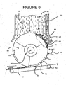
- FIGURE 6 shows a side elevated view of an application of receptacles 10 on a forming drum 40 used for collecting and fabricating absorbent cores for use in absorbent personal care articles.
- Forming receptacles 10 are disposed about at or near outer circumference of forming drum 40 in forming receptacle repository 44.
- Forming drum 40 can be designed and configured to form, in one or both a continuous and an intermittent process, individual or continuous particulate congregates 42 for use as absorbent cores in personal care absorbent articles.
- Forming drum 40 comprises a support frame or other mounting structure (not shown) for mounting forming drum 40 from a support surface and about an axis of rotation 46.
- 0nes of forming receptacle repositories 44 extend about at or near at least a portion of circumference of forming drum 40 and is supported from the mounting structure.
- 0nes of forming receptacle repositories 44 each include a forming receptacle mounted at or near a portion of the circumference of the drum.
- the forming receptacles tend to be effective in receiving and accumulating thereon one or both elongate fibers and particles of super-absorbent material, thereby to form particulate congregates 42.
- Forming chamber 50 a closed conveyance device, conveys particulate material comprising super-absorbent material and elongate fibers in harmony with direction of high air-flow, generally created by, and not limited to, vacuum forces, and shown by arrows 58.
- the high air-flow forces then direct particulate materials toward forming receptacles 10, disposed about at or near the circumference of forming drum 40, to congregate on first major surface 16 ( FIGURE 7 ) of respective forming receptacles 10.
- particulate congregates 42 are held to first major surface 16 ( FIGURE 7 ) of respective forming receptacles 10 via low air-flow forces, generally created by, and not limited to, vacuum forces, and shown by arrows 56.
- High air-flow forces 58 are of a greater magnitude of force than low air-flow forces 56, and include the amount of force necessary to promote the urging of super-absorbent particles and elongate fibers toward first major surface 16 ( FIGURE 7 ) of respective forming receptacles 10.
- low air-flow forces 56 are of a lesser magnitude of force than high air-flow forces 58, and include' the amount of force necessary to hold the particulate congregates on first major surface 16 ( FIGURE 7 ) of respective forming receptacles 10, thereby overcoming the forces of one or both gravity and centrifugal force.
- Particulate congregates 42 are released from forming wheel 40 as particulate congregates 42 pass beyond areas of low air-flow forces 56 at the bottom of wheel 40 adjacent the locus where the respective congregates are transferred to pick-up belt 54.
- Absorbent cores of absorbent personal care articles such as the cores to be made using receptacles 10 preferably.comprise a mixture 48 of super-absorbent hydrogel-forming material and elongate fibers of wood pulp in the form of fluff.
- Elongate fibers can include, and are not limited to, both softwood and hardwood fibers, as well as vessel elements, ranging in size from about 10 microns in diameter to about 70 microns in diameter.
- the elongate fibers can be up to about 5 millimeters long, preferably 1 to 3 millimeters in length.
- synthetic, polymeric, meltblown fibers or a combination of meltblown fibers and natural fibers In place of the wood pulp fluff, one can use synthetic, polymeric, meltblown fibers or a combination of meltblown fibers and natural fibers.
- Particles of super-absorbent material are generally spherically-shaped, or oblong-shaped, having a length-to-width ratio of no more than about 4/1.
- the high-absorbency material can be selected from natural, synthetic and modified natural polymers and materials.
- the high absorbency materials can be inorganic materials, such as silica gels, or organic compounds, such as cross-linked polymers.
- the high absorbency materials refer to any structure or composition, along with associated processes, which renders normally water-soluble materials substantially water insoluble but swellable, whereby absorbent properties are available but the swelled material is substantially immobile after absorbing water-based liquids.
- Such super-absorbent material can be fabricated by creating e.g. physical entanglement, crystalline domains, covalent bonds, ionic complexes and associations, hydrophilic associations such as hydrogen bonding, and hydrophobic associations or Van der Waals forces.
- a forming receptacle can be fashioned in a variety of shapes to allow the resultant absorbent core to have any of a number of shapes.
- forming receptacles can be fashioned to present absorbent cores that are rectangular, hour-glass-shaped, I-shaped, or T-shaped.
- Most absorbent cores are preferably narrower in a crotch portion than in a rear or front portion, especially where the crotch portion of the absorbent article is narrower than the rear portion or the front portion.
- Forming receptacle 10 is affixed to forming drum 40 by support structures 66.
- Forming receptacles can be affixed to support structures 66 of forming drum 40 through a variety of mechanisms including, but not limited to, welding, clamping, screws, bolts, and adhesive.
- Support structures 66 can comprise any material, preferably stainless steel, aluminum, or steel, providing ample support to secure and position receptacles 10 on forming drum 40. Some embodiments comprise alternative support structures which also all'ow air flow between adjacent forming receptacles.
- support structures 66 demonstrate a porous bridge 62 which enables air flow therethrough caused by air-flow forces, other embodiments are contemplated wherein corresponding bridge, structures do not allow air-flow between adjacent forming receptacles.
- Bridge 62 can comprise a variety of nonporous and porous materials, including forming receptacle precursor material.
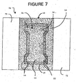
- FIGURE 7 illustrates an enlarged top view of an embodiment of forming receptacle 10 and companion attachment apparatus 72, which can be attached to a forming drum.
- forming receptacle 10 comprises a bottom wall 12, and side walls 14, which meet the bottom wall and extend up to top edge 15 thereof. While bottom wall 12 and side walls 14 are illustrated as having generally flat surfaces, embodiments comprising arcuate, angled, and rounded walls are also contemplated. Bottom wall 12 in conjunction with side walls 14 define a particulate-receiving cavity 20 in the receptacle.
- Bottom wall 12 and side walls 14 have, in combination, a first major side or surface 16 disposed toward cavity 20, and an opposing second major side or surface ( FIGURE 1 ) disposed away from cavity 20.
- An array of apertures 22 extend through receptacle 10 and connect the first and second major surfaces.
- Forming receptacle 10 can be adhered to a forming drum through a variety of mechanisms.
- FIGURE 7 illustrates a preferred embodiment for attachment to a forming drum.
- Attachment plates 72 can be adhered to forming receptacle 10 at an attachment portion 19 of forming receptacle 10 located between top edge 15 and attachment plate 72.
- the attachment portion of the forming receptacle can be altered by means such as cutting, bending, drilling, or punching, so as to provide a compatible area of attachment with respective attachment plate(s).
- Attachment plate 72 is affixed to attachment portion 19 of forming receptacle 10 by way of a variety of affixing mechanisms including, but not limited to, welds, clamps, screws, bolts, and adhesives.
- Forming receptacle 10 and affixed attachment plate 72 define a forming plate 76.
- Forming plate 76 then can be affixed to a forming drum, like e.g. the embodiment of FIGURE 6 ,through a variety of affixing mechanisms including, but not limited to, welds, clamps, screws, bolts, and adhesives.
- FIGURE 7 illustrates an attachment portion 19 which comprises apertures
- other embodiments are contemplated having less or substantially no apertures, with relationship to side walls 14 and bottom wall 12, in attachment portion 19 of forming receptacle 10.
- the invention functions to receive and collect particles of the particulate material at first major surface 16 of forming receptacle 10 and thereby to form the congregate while generally not conveying particles of the super-absorbent material, into the passage ways defining apertures of each respective forming receptacle.
- Undersize particles of super-absorbent material which do enter respective ones of the passage ways tend to pass entirely through the passage ways and not become lodged in such passage ways because of being released to pass through such passage ways. Namely, generally progressively expanding cross-sections of such passage ways along the direction of travel of such particles from top surface 16 to bottom surface 18, tends to.alleviate risk of clogging apertures in a respective forming receptacle.
- the invention also contemplates coating or treating forming receptacle material with one or more "non-stick" treatments, such as Teflon ® or electropolishing; thereby providing an additional hindrance to particles lodging in the apertures.
- throat region 28 can function as a cutting or abrading edge to cut or abrade SAM particles which are marginally too small to pass through the respective aperture, whereby throat 28 causes size reduction in some SAM particles that would otherwise not pass, allowing them to pass.
- rance surface refers to surface 16 and further refers to the surface from which SAM and fiber particles enter apertures 22.
- exit surface refers to surface 18 and further refers to the surface from which SAM and fiber particles exit apertures 22.
- a standard 30 mesh sieve comprises nominal openings of approximately 0.033 inch (0.084 cm)
- a standard 50 mesh sieve comprises nominal openings of approximately 0.012 inch (0.030 cm)
- a standard 170 mesh sieve comprises nominal openings of approximately 0.004 inch (0.010 cm). Therefore, the distance between distal walls of a respective aperture in a receptacle of the invention will tend to be less than the size of the average particles of super-absorbent material tested.
Landscapes
- Health & Medical Sciences (AREA)
- Engineering & Computer Science (AREA)
- Vascular Medicine (AREA)
- Epidemiology (AREA)
- Biomedical Technology (AREA)
- Heart & Thoracic Surgery (AREA)
- Manufacturing & Machinery (AREA)
- Life Sciences & Earth Sciences (AREA)
- Animal Behavior & Ethology (AREA)
- General Health & Medical Sciences (AREA)
- Public Health (AREA)
- Veterinary Medicine (AREA)
- Absorbent Articles And Supports Therefor (AREA)
- Orthopedics, Nursing, And Contraception (AREA)
Claims (15)
- Formbehälter (10), der zum Aufnehmen von Teilchenmaterial, das superabsorbierende Teilchen enthält, darauf eingerichtet und gestaltet ist, um so Teilchenansammlungen (42) zum Einsatz als absorbierende Kerne in absorbierenden Hygieneartikeln herzustellen, wobei der Formbehälter (10) ein Substrat umfasst, das einen Teilchenaufnahmehohlraum (20) in dem Behälter (10) bildet, das Substrat Elemente (12, 14) umfasst, die eine erste Hauptseite (16), die in Richtung des Hohlraums (20) angeordnet ist, eine gegenüberliegende zweite Hauptseite (18), die von dem Hohlraum (20) weg angeordnet ist, und eine Dicke (T) zwischen der ersten (16) und der zweiten Hauptseite (18) bilden, sowie eine Anordnung von Löchern (22), die sich durch wenigstens einen Teil des Substrats hindurch erstrecken und die erste (16) sowie die zweite Hauptseite (18) verbinden, wobei Lochwände (24) Querschnittsflächen dieser Löcher (22) entlang der Dicke (T) des Substrats bilden, und eine Ortskurve (25), die eine kleinste Querschnittsfläche bildet, sowie eine Ortskurve enthalten, die eine relativ größere Querschnittsfläche bildet, gegenüber der kleinsten Querschnittsfläche verschoben und in Richtung der zweiten Hauptseite (18) des Substrats angeordnet ist,
wobei das Substrat Bahnmaterial ist und die erste sowie die zweite Hauptseite erste bzw. zweite Hauptoberflächen sind und der Behälter (10) des Weiteren eine Matrix des Bahnmaterials zwischen jeweiligen der Löcher (22) umfasst, und Außenumfänge jeweiliger der Löcher (22) bildet. - Formbehälter nach Anspruch 1, wobei die kleinste Querschnittsfläche gegenüber sowohl der ersten als auch der zweiten Seite und dazwischen verschoben ist.
- Formbehälter nach Anspruch 1, wobei die Dicke des Substrats zwischen 0,008 cm und 0,076 cm beträgt, und wobei Strukturen der Löcher fotochemische Bearbeitung widerspiegeln, und wobei die Länge des Behälters 25 bis 76 cm (10 bis 30 Inch) beträgt.
- Verfahren zum Formen einer Ansammlung aus Teilchenmaterial (42) zum Einsatz als ein absorbierender Kern in einem absorbierenden Artikel, wobei das Teilchenmaterial (48) Teilchen aus superabsorbierendem Material umfasst und das Verfahren umfasst:(a) Transportieren des Teilchenmaterials (48) in einem gasförmigen Träger in Richtung eines Formbehälters (10), wobei der Formbehälter (10) Bahnmaterial umfasst, das einen Teilchenaufnahme-Hohlraum (20) in dem Behälter (10) bildet, das Bahnmaterial eine erste Hauptoberfläche (16), die in Richtung des Hohlraums (20) angeordnet ist, eine gegenüberliegende zweite Hauptoberfläche (18), die von dem Hohlraum (20) weg angeordnet ist, eine Dicke (T) zwischen der ersten (16) und der zweiten Hauptoberfläche (18) und eine Anordnung von Löchern (22) aufweist, die sich durch wenigstens einen Teil des Bahnmaterials erstrecken und Durchlasse zwischen der ersten (16) und der zweiten (18) Hauptoberfläche bilden, und die Durchlasse durch Lochwände (24) gebildet werden, die sich von Hauptachsen (26) der jeweiligen Durchlasse im Allgemeinen nach außen und von nahe an der ersten Hauptoberfläche (16) in Richtung der zweiten Hauptoberfläche (18) aufweiten, wobei die Durchlasse dazu neigen, sich im Allgemeinen auf dem Weg in Richtung der zweiten Hauptoberfläche (18) hinsichtlich der Querschnittsfläche auszudehnen, und projizierte Flächen der Teilchen aus dem superabsorbierenden Material im Allgemeinen größer sind als projizierte Flächen der Löcher (22); und(b) Aufnehmen und Sammeln von Teilchen des Teilchenmaterials (48) in dem Hohlraum (20) und dadurch Formen der Ansammlung (42), wobei im Allgemeinen keine Teilchen des superabsorbierenden Materials in die Durchlasse hinein transportiert werden, und untermassige Teilchen aus superabsorbierendem Material, die in jeweilige dieser Durchlasse eintreten, dazu neigen, vollständig durch die Durchlasse hindurch zu gelangen und nicht in die Durchlasse eingeschlossen werden, da sie durch die sich im Allgemeinen zunehmend ausdehnenden Querschnitte dieser Durchlasse in der Bewegungsrichtung dieser Teilchen freigegeben und durch diese Durchlasse hindurchgelassen werden.
- Verfahren nach Anspruch 4, wobei das Verfahren das Aufnehmen und Sammeln der Teilchen auf einem derartigen Formbehälter umfasst und die projizierte Fläche eines jeweiligen Lochs durch eine relativ stärker einschränkende Verengungszone des jeweiligen Durchlasses gebildet wird, wobei die Verengungszone näher an der ersten Hauptoberfläche als an der zweiten Hauptoberfläche angeordnet ist.
- Verfahren nach Anspruch 5, wobei das Verfahren Aufnehmen und Sammeln der Teilchen auf einem derartigen Formbehälter umfasst und die Querschnittsfläche einer Projektion der der Verengungszone nicht mehr als 25 % kleiner ist als die einer Projektion des jeweiligen Lochs an der ersten Oberfläche.
- Verfahren nach Anspruch 5, wobei das Verfahren Aufnehmen und Sammeln der Teilchen auf einem derartigen Formbehälter umfasst, und die Querschnittsfläche einer Projektion der der Verengungszone nicht mehr als 15 % kleiner ist als die einer Projektion des jeweiligen Lochs an der ersten Oberfläche.
- Verfahren nach Anspruch 5, wobei das Verfahren Aufnehmen und Sammeln der Teilchen auf einem derartigen Formbehälter umfasst und die Querschnittsfläche einer Projektion der Verengungszone im Wesentlichen die gleiche Größe hat wie die einer Projektion des jeweiligen Lochs an der ersten Oberfläche.
- Verfahren nach Anspruch 4, wobei das Verfahren Aufnehmen und Sammeln der Teilchen auf einem derartigen Formbehälter umfasst und ein jeweiliges Loch eine Öffnung an der ersten Hauptoberfläche bildet und die Öffnung eine offene Fläche hat, die der Fläche eines Kreises mit einem Durchmesser zwischen 0,02 cm und 0,10 cm entspricht.
- Verfahren nach Anspruch 4, wobei das Verfahren Aufnehmen und Sammeln der Teilchen auf einem derartigen Formbehälter umfasst und die Matrix aus Bahnmaterial im Allgemeinen eine minimale projizierte Breite zwischen jeweiligen der Löcher zwischen 0,008 cm und 0,038 cm bildet.
- Verfahren nach Anspruch 4, wobei das Verfahren Aufnehmen und Sammeln der Teilchen auf einem derartigen Formbehälter umfasst und Lochwände aneinandergrenzender der Löcher die zweite Hauptoberfläche schneiden, ohne einander zu schneiden, und diese Lochwände aneinandergrenzender erster und zweiter der Löcher einen nominellen Abstand dazwischen bilden, ohne einander zu schneiden.
- Verfahren nach Anspruch 4, wobei das Verfahren Aufnehmen und Sammeln der Teilchen auf einem derartigen Formbehälter umfasst und die Anordnung von Löchern in einer Folge paralleler Reihen von Löchern angeordnet ist, Abstand zwischen Löchern in einer bestimmten Reihe von Reihe zu Reihe im Wesentlichen konstant ist, und die Reihen seitlich in Bezug zueinander so verschoben sind, dass aneinandergrenzende Löcher in aneinandergrenzenden Reihen Winkel zwischen 50 Grad und 90 Grad in Bezug auf eine imaginäre Linie parallel zu den Reihen bilden.
- Verfahren nach Anspruch 4, wobei das Verfahren Aufnehmen und Sammeln der Teilchen auf einem derartigen Formbehälter umfasst und die Löcher, gemessen an einem kleinsten Öffnungsquerschnitt, der durch jedes derartige Loch gebildet wird, zusammen eine gesamte offene Fläche bilden, die wenigstens 35 % der zusammengefassten Flächen der unteren Wand und der Seitenwand darstellt.
- Verfahren nach Anspruch 4, wobei das Verfahren Aufnehmen und Sammeln der Teilchen auf einem derartigen Formbehälter umfasst und das superabsorbierende Material im Allgemeinen kugelförmig ist.
- Verfahren nach Anspruch 4, wobei das Verfahren Aufnehmen und Sammeln der Teilchen auf einem derartigen Formbehälter umfasst und die Teilchen aus superabsorbierendem Material im Allgemeinen länglich geformt sind und ein Verhältnis von Länge zu Breite von nicht mehr als 4:1 haben.
Priority Applications (1)
| Application Number | Priority Date | Filing Date | Title |
|---|---|---|---|
| DE60125415.5T DE60125415T3 (de) | 2000-10-23 | 2001-10-22 | Formeinsatz |
Applications Claiming Priority (3)
| Application Number | Priority Date | Filing Date | Title |
|---|---|---|---|
| US694374 | 1985-01-24 | ||
| US09/694,374 US6630088B1 (en) | 2000-10-23 | 2000-10-23 | Forming media with enhanced air flow properties |
| PCT/US2001/049987 WO2002036056A2 (en) | 2000-10-23 | 2001-10-22 | Forming receptacle |
Publications (3)
| Publication Number | Publication Date |
|---|---|
| EP1357874A2 EP1357874A2 (de) | 2003-11-05 |
| EP1357874B1 EP1357874B1 (de) | 2006-12-20 |
| EP1357874B2 true EP1357874B2 (de) | 2014-02-12 |
Family
ID=24788557
Family Applications (1)
| Application Number | Title | Priority Date | Filing Date |
|---|---|---|---|
| EP01985613.7A Expired - Lifetime EP1357874B2 (de) | 2000-10-23 | 2001-10-22 | Formeinsatz |
Country Status (8)
| Country | Link |
|---|---|
| US (1) | US6630088B1 (de) |
| EP (1) | EP1357874B2 (de) |
| JP (1) | JP4216069B2 (de) |
| AU (1) | AU2002235248A1 (de) |
| DE (1) | DE60125415T3 (de) |
| MX (1) | MXPA03003053A (de) |
| NO (1) | NO20031757L (de) |
| WO (1) | WO2002036056A2 (de) |
Families Citing this family (25)
| Publication number | Priority date | Publication date | Assignee | Title |
|---|---|---|---|---|
| DE60325672D1 (de) * | 2002-06-10 | 2009-02-26 | Kao Corp | Ein absorbierender Kern und Verfahren zu dessen Herstellung |
| JP3837104B2 (ja) * | 2002-08-22 | 2006-10-25 | 日精樹脂工業株式会社 | カーボンナノ材と金属材料の複合成形方法及び複合金属製品 |
| US7359692B2 (en) * | 2003-06-30 | 2008-04-15 | Zarbana Digital Fund, Llc | Method of and device for antennae diversity switching |
| US7157033B2 (en) * | 2004-09-29 | 2007-01-02 | Kimberly-Clark Worldwide, Inc. | Method and apparatus for scarfing fibrous substrates |
| JP4782489B2 (ja) * | 2005-06-27 | 2011-09-28 | トヨタ紡織株式会社 | フィルタ用濾材 |
| US7682554B2 (en) * | 2005-08-30 | 2010-03-23 | Kimberly-Clark Worldwide, Inc. | Method and apparatus to mechanically shape a composite structure |
| US7687012B2 (en) * | 2005-08-30 | 2010-03-30 | Kimberly-Clark Worldwide, Inc. | Method and apparatus to shape a composite structure without contact |
| US20070044903A1 (en) * | 2005-08-30 | 2007-03-01 | Kimberly-Clark Worldwide, Inc. | Method and apparatus for making absorbent article with core wrap |
| US8484213B2 (en) * | 2005-08-31 | 2013-07-09 | International Business Machines Corporation | Heterogenous high availability cluster manager |
| CN101277663B (zh) * | 2005-09-29 | 2012-02-08 | 大王制纸株式会社 | 吸收体的纤维堆积装置、纤维堆积滚筒以及使用它们的吸收体的制造方法、和具有由该制造方法制造的吸收体的吸收性物品 |
| US20080082068A1 (en) * | 2006-10-02 | 2008-04-03 | Jian Qin | Absorbent articles comprising carboxyalkyl cellulose fibers having permanent and non-permanent crosslinks |
| US20080082069A1 (en) * | 2006-10-02 | 2008-04-03 | Jian Qin | Absorbent articles comprising carboxyalkyl cellulose fibers having non-permanent and temporary crosslinks |
| US7549853B2 (en) * | 2006-11-15 | 2009-06-23 | The Procter & Gamble Company | Apparatus for making air-laid structures |
| US7704439B2 (en) * | 2006-11-15 | 2010-04-27 | The Procter & Gamble Company | Method for making air-laid structures |
| US7704441B2 (en) * | 2006-11-15 | 2010-04-27 | The Procter & Gamble Company | Method for making air-laid structures |
| US7553146B2 (en) | 2006-11-15 | 2009-06-30 | The Procter & Gamble Company | Apparatus for making air-laid structures |
| US8039683B2 (en) | 2007-10-15 | 2011-10-18 | Kimberly-Clark Worldwide, Inc. | Absorbent composites having improved fluid wicking and web integrity |
| US8552251B2 (en) | 2010-10-08 | 2013-10-08 | Kimberly-Clark Worldwide, Inc. | Article with health-benefit agent delivery system |
| US10562281B2 (en) | 2011-08-02 | 2020-02-18 | Kimberly-Clark Worldwide, Inc. | Cooling signal device for use in an absorbent article |
| US8911681B2 (en) | 2011-09-12 | 2014-12-16 | Kimberly-Clark Worldwide, Inc. | Wetness indicator having varied hues |
| US8754005B2 (en) | 2012-08-28 | 2014-06-17 | Kimberly-Clark Worldwide, Inc. | Color-changing composition and material |
| AU2013308066B2 (en) | 2012-08-31 | 2017-07-20 | Kimberly-Clark Worldwide, Inc. | Method of manufacture of article for delivering health-benefit agent |
| RU2666104C1 (ru) | 2015-01-23 | 2018-09-05 | Кимберли-Кларк Ворлдвайд, Инк. | Способ изготовления впитывающих структур с перемычками |
| US20220257428A1 (en) | 2019-05-30 | 2022-08-18 | Kimberly-Clark Worldwide, Inc. | Apparatuses and methods for manufacturing absorbent structures including flexible masking media |
| DE102021006409A1 (de) | 2021-12-29 | 2023-06-29 | Paul Hartmann Ag | Verfahren zum Dosieren und Applizieren einer kleinen Menge eines partikulären Materials |
Citations (5)
| Publication number | Priority date | Publication date | Assignee | Title |
|---|---|---|---|---|
| WO1981002879A1 (en) † | 1980-03-31 | 1981-10-15 | Caterpillar Tractor Co | Bulk material handler and feeder |
| US4383896A (en) † | 1980-04-15 | 1983-05-17 | Stork Screens B.V. | Process of electroforming a screen, more particularly a cylindrical screen |
| US4610678A (en) † | 1983-06-24 | 1986-09-09 | Weisman Paul T | High-density absorbent structures |
| US5004579A (en) † | 1989-05-26 | 1991-04-02 | Mcneil-Ppc-Inc. | Methods and apparatus for selective placement of fibrous material in formed fibrous articles |
| US5302100A (en) † | 1991-05-29 | 1994-04-12 | Winkler & Dunnebier | Drum insert for a device for producing shaped pads of fibrous material surrounded on all sides by foils |
Family Cites Families (8)
| Publication number | Priority date | Publication date | Assignee | Title |
|---|---|---|---|---|
| US3518726A (en) | 1967-09-15 | 1970-07-07 | Kimberly Clark Co | Machine for making sanitary napkins |
| US4140508A (en) * | 1977-10-25 | 1979-02-20 | Owens-Corning Fiberglas Corporation | Method and apparatus for collecting strand formed from streams of molten material |
| US4592708A (en) | 1984-02-01 | 1986-06-03 | The Procter & Gamble Company | Apparatus for making airlaid articles |
| US4674966A (en) | 1984-04-02 | 1987-06-23 | Winkler & Dunnebier | Apparatus for forming fibrous pads |
| US4761258A (en) | 1985-12-10 | 1988-08-02 | Kimberly-Clark Corporation | Controlled formation of light and heavy fluff zones |
| US4666647A (en) | 1985-12-10 | 1987-05-19 | Kimberly-Clark Corporation | Apparatus and process for forming a laid fibrous web |
| EP0338111B1 (de) | 1988-04-21 | 1993-06-30 | Koyo Disposable Goods Company | Verfahren zur Herstellung von sanitären Artikeln und Vorrichtung zur Durchführung dieses Verfahrens |
| US5466409A (en) | 1993-10-19 | 1995-11-14 | Kimberly-Clark Corporation | Forming belt for three-dimensional forming applications |
-
2000
- 2000-10-23 US US09/694,374 patent/US6630088B1/en not_active Expired - Lifetime
-
2001
- 2001-10-22 MX MXPA03003053A patent/MXPA03003053A/es active IP Right Grant
- 2001-10-22 WO PCT/US2001/049987 patent/WO2002036056A2/en not_active Ceased
- 2001-10-22 EP EP01985613.7A patent/EP1357874B2/de not_active Expired - Lifetime
- 2001-10-22 DE DE60125415.5T patent/DE60125415T3/de not_active Expired - Lifetime
- 2001-10-22 JP JP2002538868A patent/JP4216069B2/ja not_active Expired - Fee Related
- 2001-10-22 AU AU2002235248A patent/AU2002235248A1/en not_active Abandoned
-
2003
- 2003-04-15 NO NO20031757A patent/NO20031757L/no not_active Application Discontinuation
Patent Citations (5)
| Publication number | Priority date | Publication date | Assignee | Title |
|---|---|---|---|---|
| WO1981002879A1 (en) † | 1980-03-31 | 1981-10-15 | Caterpillar Tractor Co | Bulk material handler and feeder |
| US4383896A (en) † | 1980-04-15 | 1983-05-17 | Stork Screens B.V. | Process of electroforming a screen, more particularly a cylindrical screen |
| US4610678A (en) † | 1983-06-24 | 1986-09-09 | Weisman Paul T | High-density absorbent structures |
| US5004579A (en) † | 1989-05-26 | 1991-04-02 | Mcneil-Ppc-Inc. | Methods and apparatus for selective placement of fibrous material in formed fibrous articles |
| US5302100A (en) † | 1991-05-29 | 1994-04-12 | Winkler & Dunnebier | Drum insert for a device for producing shaped pads of fibrous material surrounded on all sides by foils |
Also Published As
| Publication number | Publication date |
|---|---|
| WO2002036056A2 (en) | 2002-05-10 |
| WO2002036056A3 (en) | 2003-09-04 |
| DE60125415T2 (de) | 2007-07-05 |
| US6630088B1 (en) | 2003-10-07 |
| JP2004532657A (ja) | 2004-10-28 |
| AU2002235248A1 (en) | 2002-05-15 |
| DE60125415D1 (de) | 2007-02-01 |
| NO20031757L (no) | 2003-06-17 |
| DE60125415T3 (de) | 2014-07-03 |
| MXPA03003053A (es) | 2003-07-14 |
| JP4216069B2 (ja) | 2009-01-28 |
| EP1357874B1 (de) | 2006-12-20 |
| NO20031757D0 (no) | 2003-04-15 |
| EP1357874A2 (de) | 2003-11-05 |
Similar Documents
| Publication | Publication Date | Title |
|---|---|---|
| EP1357874B2 (de) | Formeinsatz | |
| JP3983172B2 (ja) | 改善された坪量をもつ堆積繊維性ウェブを形成する装置及びプロセス | |
| JP4451490B2 (ja) | 積繊ドラム | |
| EP1920743B2 (de) | Luftgeformtes Fasernetz | |
| US6630096B2 (en) | Multi-stage forming drum commutator | |
| JP6247641B2 (ja) | 粉粒体供給方法と供給装置 | |
| JP6247640B2 (ja) | 粉粒体収容シートの製造方法と製造装置 | |
| JP3248687B2 (ja) | 成形体の製造方法及び製造装置 | |
| JP2009232959A (ja) | 吸収体の積繊装置及び吸収体 | |
| JP4275050B2 (ja) | 吸収体の製造装置 | |
| CA2057355A1 (en) | Hydrosonically embedded soft thin film materials and process for forming said materials | |
| JP3968700B2 (ja) | 微小球の分級方法および微小球分級装置 | |
| JP2530151Y2 (ja) | 篩 網 |
Legal Events
| Date | Code | Title | Description |
|---|---|---|---|
| PUAI | Public reference made under article 153(3) epc to a published international application that has entered the european phase |
Free format text: ORIGINAL CODE: 0009012 |
|
| 17P | Request for examination filed |
Effective date: 20030521 |
|
| AK | Designated contracting states |
Kind code of ref document: A2 Designated state(s): AT BE CH CY DE DK ES FI FR GB GR IE IT LI LU MC NL PT SE TR |
|
| AX | Request for extension of the european patent |
Extension state: AL LT LV MK RO SI |
|
| RBV | Designated contracting states (corrected) |
Designated state(s): AT BE CH CY DE DK ES FR GB IT LI SE |
|
| 17Q | First examination report despatched |
Effective date: 20050408 |
|
| GRAP | Despatch of communication of intention to grant a patent |
Free format text: ORIGINAL CODE: EPIDOSNIGR1 |
|
| RBV | Designated contracting states (corrected) |
Designated state(s): DE ES FR GB IT SE |
|
| GRAS | Grant fee paid |
Free format text: ORIGINAL CODE: EPIDOSNIGR3 |
|
| GRAA | (expected) grant |
Free format text: ORIGINAL CODE: 0009210 |
|
| AK | Designated contracting states |
Kind code of ref document: B1 Designated state(s): DE ES FR GB IT SE |
|
| REG | Reference to a national code |
Ref country code: GB Ref legal event code: FG4D |
|
| REF | Corresponds to: |
Ref document number: 60125415 Country of ref document: DE Date of ref document: 20070201 Kind code of ref document: P |
|
| PG25 | Lapsed in a contracting state [announced via postgrant information from national office to epo] |
Ref country code: SE Free format text: LAPSE BECAUSE OF FAILURE TO SUBMIT A TRANSLATION OF THE DESCRIPTION OR TO PAY THE FEE WITHIN THE PRESCRIBED TIME-LIMIT Effective date: 20070320 |
|
| PG25 | Lapsed in a contracting state [announced via postgrant information from national office to epo] |
Ref country code: ES Free format text: LAPSE BECAUSE OF FAILURE TO SUBMIT A TRANSLATION OF THE DESCRIPTION OR TO PAY THE FEE WITHIN THE PRESCRIBED TIME-LIMIT Effective date: 20070331 |
|
| ET | Fr: translation filed | ||
| PLBI | Opposition filed |
Free format text: ORIGINAL CODE: 0009260 |
|
| PLAX | Notice of opposition and request to file observation + time limit sent |
Free format text: ORIGINAL CODE: EPIDOSNOBS2 |
|
| 26 | Opposition filed |
Opponent name: PROCTER & GAMBLE, INC. Effective date: 20070920 |
|
| PLAF | Information modified related to communication of a notice of opposition and request to file observations + time limit |
Free format text: ORIGINAL CODE: EPIDOSCOBS2 |
|
| PLBB | Reply of patent proprietor to notice(s) of opposition received |
Free format text: ORIGINAL CODE: EPIDOSNOBS3 |
|
| PLAB | Opposition data, opponent's data or that of the opponent's representative modified |
Free format text: ORIGINAL CODE: 0009299OPPO |
|
| PLAB | Opposition data, opponent's data or that of the opponent's representative modified |
Free format text: ORIGINAL CODE: 0009299OPPO |
|
| R26 | Opposition filed (corrected) |
Opponent name: PROCTER & GAMBLE, INC. Effective date: 20070920 |
|
| APBM | Appeal reference recorded |
Free format text: ORIGINAL CODE: EPIDOSNREFNO |
|
| APBP | Date of receipt of notice of appeal recorded |
Free format text: ORIGINAL CODE: EPIDOSNNOA2O |
|
| APAH | Appeal reference modified |
Free format text: ORIGINAL CODE: EPIDOSCREFNO |
|
| APBQ | Date of receipt of statement of grounds of appeal recorded |
Free format text: ORIGINAL CODE: EPIDOSNNOA3O |
|
| PLAB | Opposition data, opponent's data or that of the opponent's representative modified |
Free format text: ORIGINAL CODE: 0009299OPPO |
|
| R26 | Opposition filed (corrected) |
Opponent name: PROCTER & GAMBLE, INC. Effective date: 20070920 |
|
| PLAB | Opposition data, opponent's data or that of the opponent's representative modified |
Free format text: ORIGINAL CODE: 0009299OPPO |
|
| R26 | Opposition filed (corrected) |
Opponent name: PROCTER & GAMBLE, INC. Effective date: 20070920 |
|
| PLAB | Opposition data, opponent's data or that of the opponent's representative modified |
Free format text: ORIGINAL CODE: 0009299OPPO |
|
| APBU | Appeal procedure closed |
Free format text: ORIGINAL CODE: EPIDOSNNOA9O |
|
| R26 | Opposition filed (corrected) |
Opponent name: PROCTER & GAMBLE, INC. Effective date: 20070920 |
|
| REG | Reference to a national code |
Ref country code: DE Ref legal event code: R082 Ref document number: 60125415 Country of ref document: DE Representative=s name: ZIMMERMANN & PARTNER, DE Ref country code: DE Ref legal event code: R082 Ref document number: 60125415 Country of ref document: DE Representative=s name: ZIMMERMANN & PARTNER PATENTANWAELTE MBB, DE |
|
| PUAH | Patent maintained in amended form |
Free format text: ORIGINAL CODE: 0009272 |
|
| STAA | Information on the status of an ep patent application or granted ep patent |
Free format text: STATUS: PATENT MAINTAINED AS AMENDED |
|
| 27A | Patent maintained in amended form |
Effective date: 20140212 |
|
| AK | Designated contracting states |
Kind code of ref document: B2 Designated state(s): DE ES FR GB IT SE |
|
| REG | Reference to a national code |
Ref country code: DE Ref legal event code: R102 Ref document number: 60125415 Country of ref document: DE |
|
| REG | Reference to a national code |
Ref country code: DE Ref legal event code: R102 Ref document number: 60125415 Country of ref document: DE Effective date: 20140212 |
|
| REG | Reference to a national code |
Ref country code: FR Ref legal event code: PLFP Year of fee payment: 15 |
|
| PGFP | Annual fee paid to national office [announced via postgrant information from national office to epo] |
Ref country code: FR Payment date: 20151019 Year of fee payment: 15 |
|
| PGFP | Annual fee paid to national office [announced via postgrant information from national office to epo] |
Ref country code: GB Payment date: 20161027 Year of fee payment: 16 |
|
| REG | Reference to a national code |
Ref country code: FR Ref legal event code: ST Effective date: 20170630 |
|
| PG25 | Lapsed in a contracting state [announced via postgrant information from national office to epo] |
Ref country code: FR Free format text: LAPSE BECAUSE OF NON-PAYMENT OF DUE FEES Effective date: 20161102 |
|
| GBPC | Gb: european patent ceased through non-payment of renewal fee |
Effective date: 20171022 |
|
| PG25 | Lapsed in a contracting state [announced via postgrant information from national office to epo] |
Ref country code: GB Free format text: LAPSE BECAUSE OF NON-PAYMENT OF DUE FEES Effective date: 20171022 |
|
| PGFP | Annual fee paid to national office [announced via postgrant information from national office to epo] |
Ref country code: IT Payment date: 20201023 Year of fee payment: 20 Ref country code: DE Payment date: 20201028 Year of fee payment: 20 |
|
| REG | Reference to a national code |
Ref country code: DE Ref legal event code: R071 Ref document number: 60125415 Country of ref document: DE |