EP1357580B1 - Niederdruckentladungslampe mit Abschaltvorrichtung am Lebensdauerende - Google Patents
Niederdruckentladungslampe mit Abschaltvorrichtung am Lebensdauerende Download PDFInfo
- Publication number
- EP1357580B1 EP1357580B1 EP03009249A EP03009249A EP1357580B1 EP 1357580 B1 EP1357580 B1 EP 1357580B1 EP 03009249 A EP03009249 A EP 03009249A EP 03009249 A EP03009249 A EP 03009249A EP 1357580 B1 EP1357580 B1 EP 1357580B1
- Authority
- EP
- European Patent Office
- Prior art keywords
- bead
- paste
- discharge lamp
- pressure discharge
- low
- Prior art date
- Legal status (The legal status is an assumption and is not a legal conclusion. Google has not performed a legal analysis and makes no representation as to the accuracy of the status listed.)
- Expired - Lifetime
Links
- 239000011324 bead Substances 0.000 claims description 35
- 229910052987 metal hydride Inorganic materials 0.000 claims description 28
- 150000004681 metal hydrides Chemical class 0.000 claims description 27
- 230000005855 radiation Effects 0.000 claims description 14
- 229910000048 titanium hydride Inorganic materials 0.000 claims description 10
- 239000011521 glass Substances 0.000 claims description 9
- -1 titanium hydride Chemical compound 0.000 claims description 9
- 229910052751 metal Inorganic materials 0.000 claims description 7
- 239000002184 metal Substances 0.000 claims description 7
- 239000000463 material Substances 0.000 claims description 5
- RMIBFJWHAHLICA-UHFFFAOYSA-N [K].[Ba] Chemical compound [K].[Ba] RMIBFJWHAHLICA-UHFFFAOYSA-N 0.000 claims description 4
- 229910052916 barium silicate Inorganic materials 0.000 claims description 4
- 239000005368 silicate glass Substances 0.000 claims description 4
- 239000006254 rheological additive Substances 0.000 claims description 3
- 235000001674 Agaricus brunnescens Nutrition 0.000 claims description 2
- RTAQQCXQSZGOHL-UHFFFAOYSA-N Titanium Chemical compound [Ti] RTAQQCXQSZGOHL-UHFFFAOYSA-N 0.000 claims description 2
- QCWXUUIWCKQGHC-UHFFFAOYSA-N Zirconium Chemical compound [Zr] QCWXUUIWCKQGHC-UHFFFAOYSA-N 0.000 claims description 2
- VSTCOQVDTHKMFV-UHFFFAOYSA-N [Ti].[Hf] Chemical compound [Ti].[Hf] VSTCOQVDTHKMFV-UHFFFAOYSA-N 0.000 claims description 2
- 229910045601 alloy Inorganic materials 0.000 claims description 2
- 239000000956 alloy Substances 0.000 claims description 2
- 229910052735 hafnium Inorganic materials 0.000 claims description 2
- VBJZVLUMGGDVMO-UHFFFAOYSA-N hafnium atom Chemical compound [Hf] VBJZVLUMGGDVMO-UHFFFAOYSA-N 0.000 claims description 2
- INIGCWGJTZDVRY-UHFFFAOYSA-N hafnium zirconium Chemical compound [Zr].[Hf] INIGCWGJTZDVRY-UHFFFAOYSA-N 0.000 claims description 2
- 229910001092 metal group alloy Inorganic materials 0.000 claims description 2
- 229910052719 titanium Inorganic materials 0.000 claims description 2
- 239000010936 titanium Substances 0.000 claims description 2
- PMTRSEDNJGMXLN-UHFFFAOYSA-N titanium zirconium Chemical compound [Ti].[Zr] PMTRSEDNJGMXLN-UHFFFAOYSA-N 0.000 claims description 2
- 229910052726 zirconium Inorganic materials 0.000 claims description 2
- 239000004020 conductor Substances 0.000 claims 4
- 229910052739 hydrogen Inorganic materials 0.000 description 8
- 239000001257 hydrogen Substances 0.000 description 8
- UFHFLCQGNIYNRP-UHFFFAOYSA-N Hydrogen Chemical compound [H][H] UFHFLCQGNIYNRP-UHFFFAOYSA-N 0.000 description 7
- 238000010438 heat treatment Methods 0.000 description 5
- 238000000354 decomposition reaction Methods 0.000 description 3
- 239000002245 particle Substances 0.000 description 2
- 238000010276 construction Methods 0.000 description 1
- 238000012217 deletion Methods 0.000 description 1
- 230000037430 deletion Effects 0.000 description 1
- 230000001419 dependent effect Effects 0.000 description 1
- 150000002431 hydrogen Chemical class 0.000 description 1
- 238000011835 investigation Methods 0.000 description 1
- 238000004519 manufacturing process Methods 0.000 description 1
- 230000002028 premature Effects 0.000 description 1
Images
Classifications
-
- A—HUMAN NECESSITIES
- A47—FURNITURE; DOMESTIC ARTICLES OR APPLIANCES; COFFEE MILLS; SPICE MILLS; SUCTION CLEANERS IN GENERAL
- A47C—CHAIRS; SOFAS; BEDS
- A47C7/00—Parts, details, or accessories of chairs or stools
- A47C7/54—Supports for the arms
- A47C7/541—Supports for the arms of adjustable type
-
- H—ELECTRICITY
- H01—ELECTRIC ELEMENTS
- H01J—ELECTRIC DISCHARGE TUBES OR DISCHARGE LAMPS
- H01J61/00—Gas-discharge or vapour-discharge lamps
- H01J61/70—Lamps with low-pressure unconstricted discharge having a cold pressure < 400 Torr
-
- A—HUMAN NECESSITIES
- A47—FURNITURE; DOMESTIC ARTICLES OR APPLIANCES; COFFEE MILLS; SPICE MILLS; SUCTION CLEANERS IN GENERAL
- A47C—CHAIRS; SOFAS; BEDS
- A47C1/00—Chairs adapted for special purposes
- A47C1/02—Reclining or easy chairs
- A47C1/022—Reclining or easy chairs having independently-adjustable supporting parts
- A47C1/03—Reclining or easy chairs having independently-adjustable supporting parts the parts being arm-rests
- A47C1/0307—Reclining or easy chairs having independently-adjustable supporting parts the parts being arm-rests adjustable rectilinearly in horizontal direction
-
- H—ELECTRICITY
- H01—ELECTRIC ELEMENTS
- H01J—ELECTRIC DISCHARGE TUBES OR DISCHARGE LAMPS
- H01J61/00—Gas-discharge or vapour-discharge lamps
- H01J61/02—Details
- H01J61/24—Means for obtaining or maintaining the desired pressure within the vessel
- H01J61/28—Means for producing, introducing, or replenishing gas or vapour during operation of the lamp
Definitions
- the invention relates to a low-pressure discharge lamp with a tubular discharge vessel made of glass, the free ends are gas-tight, with two electrode systems, each with a coil, two power supply lines and a glass bead, the power supply with their ends in the gas-tight ends of the discharge vessel and Holder are fused in a region between the coil and the discharge vessel melt into the bead and with a device for switching off the lamp at the end of life consisting of a paste containing a metal hydride and is mounted on the bead.
- European Patent EP 0 727 809 discloses such a low-pressure discharge lamp.
- the lamp goes into a cold cathode operation, which causes an increase in the cathode drop voltage and thus a strong heating of the metal parts in the lamp.
- the sharp increase in the temperature of the metal parts leads to a disintegration of the metal hydride in the paste, which is mounted in the radiation region of the coil and in contact with the power supply lines on the glass bead.
- the metal hydride in particular Titanhydrides hydrogen is released and the discharge extinguished due to the increasing burning voltage of the lamp.
- the object of the invention is therefore to provide a lamp with a device for switching off the low-pressure discharge lamp at the end of life according to the preamble of claim 1, are prevented in the early failures due to high Wendelrichströme the ballast.
- the paste with the metal hydride is applied to the bead in the radiation shadow with respect to the thermal radiation emanating from the filament of the lamp during operation. This can prevent heating of the paste and thus of the metal hydride by directly acting heat radiation from the coil.
- the paste is applied to the bead so that it has no electrical contact with the power supply wires. As a result, heat conduction from the power supply into the paste is largely prevented.
- the pearl consists of a potassium barium silicate glass, which has a specific electrical resistance of greater than or equal to 10 10 ⁇ cm at 350 ° C.
- An electrical conduction of the bead is optimally prevented up to the release temperature of the hydrogen at 400 ° C.
- the glass bead advantageously has no spherical shape, but a circular cylindrical or cylindrical shape whose axis is aligned transversely to the axis of the discharge vessel in this area, wherein the power supply lines are melted near the two ends of the circular cylindrical bead and the paste with the metal hydride on the from the helix facing away from the part of the bead in the radiation shadow of the helix is attached.
- a mushroom-like shape wherein the cap of the mushroom faces the helix and the paste with the metal hydride is below the cap in the radiation shadow of the helix. This optimally prevents heating of the paste and thus of the metal hydride by the radiant heat.
- next point of the bead facing the gas-tight closure of the discharge vessel has at least a distance of 2 mm from this closure. Unless this is considered, closing the discharge vessel during lamp production and the large amount of heat that occurs can result in glazing of the bead and thus release of the hydrogen from the metal hydride compound.
- the metal hydride in the paste advantageously contains a metal from the group consisting of titanium, zirconium and / or hafnium or a metal alloy from the group of the alloys titanium-zirconium, titanium-hafnium and / or zirconium hafnium as metal for the metal hydride.
- a paste material for the metal hydride is in particular a rheological additive with a proportion of less than or equal to 50 wt.%.
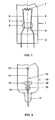
- FIG. 1 shows an end of a first embodiment of a compact low-pressure discharge lamp with a multiply bent discharge vessel.
- the ends of the discharge vessel are closed by pinching, wherein in the here shown and sealed by a pinch seal 2 end 1 of the discharge vessel, the two power supply lines 5, 6 of an electrode system 3 are melted.
- the electrode system further consists of a coil 7 and a glass bead 8, which is located approximately in the middle between the coil 7 and the pinch seal 2 and in which the two power supply lines are 5.6 melted.
- the glass bead 8 consists of a potassium barium silicate glass and has a substantially nikzylinder- or cylindrical shape with rounded ends, wherein the axis of the cylinder or the roller transverse to the axis of the discharge vessel in this area.
- the pearl 8 has a length of 7 mm and a circle diameter of 4 mm.
- the two power supply lines 5, 6 are melted near the two ends of the bead 8.
- a paste 9 of a titanium hydride and a rheological additive is applied, the point with the paste being in the radiation shadow with respect to the helix 7.
- FIG. 2 shows a second embodiment of a discharge vessel end 10 of a compact low-pressure discharge lamp with a similar structure of the electrode system.
- the end of the discharge vessel 10 with the pinch 11 is here rotated by 90 ° in its axis.
- the electrode system 12 with a coil 13 and power leads 14 (it is in this View only a power supply visible) differs from the system in Figure 1 in that here the bead 15 of a potassium barium silicate glass has a mushroom-shaped shape with a cap 16 and a handle 17, wherein the cap 16 of the coil 13 faces , As a result, the paste 18 applied below the cap 16 on both sides of the stem 17 is in contact with the titanium hydride in the radiation shadow of the helix 13.
Landscapes
- Health & Medical Sciences (AREA)
- Dentistry (AREA)
- General Health & Medical Sciences (AREA)
- Vessels And Coating Films For Discharge Lamps (AREA)
- Discharge Lamp (AREA)
Description
- Die Erfindung betrifft eine Niederdruckentladungslampe mit einem rohrförmigen Entladungsgefäß aus Glas, dessen freie Enden gasdicht verschlossen sind, mit zwei Elektrodensystemen mit jeweils einer Wendel, zwei Stromzuführungen und einer Perle aus Glas, wobei die Stromzuführungen mit ihren Enden in die gasdicht verschlossenen Enden des Entladungsgefäßes und zur Halterung in einem Bereich zwischen der Wendel und der Entladungsgefäßeinschmelzung in die Perle eingeschmolzen sind und mit einer Vorrichtung zur Abschaltung der Lampe am Lebensdauerende bestehend aus einer Paste, die ein Metallhydrid enthält und auf der Perle angebracht ist.
- Aus der europäischen Patentschrift EP 0 727 809 ist eine solche Niederdruckentladungslampe bekannt. Am Lebensdauerende der Niederdruckentladungslampe, wenn die Wendel bricht oder das Emittermaterial aufgebraucht ist, geht die Lampe in einen Kaltkathodenbetrieb über, der einen Anstieg der Kathodenfallspannung und damit eine starke Erwärmung der Metallteile in der Lampe zur Folge hat. Der starke Anstieg der Temperatur der Metallteile führt zu einem Zerfall des Metallhydrids in der Paste, die im Strahlungsbereich der Wendel und mit Kontakt zu den Stromzuführungen auf der Glasperle angebracht ist. Durch den Zerfall des Metallhydrids, insbesondere Titanhydrids wird Wasserstoff freigesetzt und die Entladung aufgrund der ansteigenden Brennspannung der Lampe gelöscht.
- Eine Anordnung der Metallhydrid enthaltenden Paste im Strahlungsbereich der Wendel und im Wärmekontakt mit den Stromzuführungen führt zu einem sicheren Freisetzen des Wasserstoffs und damit einem Löschen der Lampe am Lebensdauerende. Es hat sich jedoch gezeigt, dass es mit einer solchen Konstruktion zu Frühausfällen der Niederdruckentladungslampe kommen kann, wenn diese an einem Vorschaltgerät betrieben wird, das in der Vorheizphase einen Anstieg des Wendelheizstroms zulässt, bis die Lampe gezündet hat. In diesem Fall kann der Anstieg der Wendelstrahlung und die Erwärmung der Stromzuführungen eine vorzeitige Zersetzung des Metallhydrids zur Folge haben. Durch den freigesetzten Wasserstoff wird dann die Lampe vor Erreichen des Lebensdauerendes durch Emitterverbrauch gelöscht.
- Aufgabe der Erfindung ist es daher eine Lampe mit einer Vorrichtung zur Abschaltung der Niederdruckentladungslampe am Lebensdauerende gemäß dem Oberbegriff des Anspruchs 1 bereitzustellen, bei der Frühausfälle aufgrund hoher Wendelheizströme des Vorschaltgeräts verhindert werden.
- Diese Aufgabe wird bei einer Niederdruckentladungslampe mit den Merkmalen des Oberbegriffs des Anspruchs 1 durch die Merkmale des kennzeichnenden Teils des Anspruchs 1 gelöst. Besonders vorteilhafte Ausgestaltungen finden sich in den abhängigen Ansprüchen.
- Durch die Verwendung eines Materials für die Perle, das mindestens einen spezifischen elektrischen Widerstand von größer 108 Ωcm bei 350°C besitzt, kann sichergestellt werden, dass das Material der Perle bis zur Zersetzungstemperatur des Metallhydrids nicht leitfähig wird. Ein Aufheizen des Metallhydrids durch direkte Wärmeleitung wird weitgehend unterbunden.
- Weiterhin ist die Paste mit dem Metallhydrid erfindungsgemäß bezüglich der von der Wendel der Lampe im Betrieb ausgehenden Wärmestrahlung im Strahlungsschatten auf der Perle aufgebracht. Dadurch kann ein Aufheizen der Paste und somit des Metallhydrids durch direkt einwirkende Wärmestrahlung von der Wendel verhindert werden. Außerdem ist die Paste so auf der Perle aufgebracht, das sie keinen elektrischen Kontakt zu den Stromzuführungsdrähten besitzt. Dadurch wird eine Wärmeleitung von der Stromzuführung in die Paste weitgehend unterbunden.
- Vorteilhaft besteht daher die Perle aus einem Kali-Barium-Silikatglas, das einen spezifischen elektrischen Widerstand von größer gleich 1010 Ωcm bei 350°C aufweist. Eine elektrische Leitung der Perle wird so bis hin zur Freisetzungstemperatur des Wasserstoffs bei 400 °C optimal verhindert.
- Weiterhin besitzt die Glasperle vorteilhaft keine kugelige Form, sondern eine kreiszylinder- oder walzenförmige Form, deren Achse quer zur Achse des Entladungsgefäßes in diesem Bereich ausgerichtet ist, wobei die Stromzuführungen nahe den beiden Enden der kreiszylinderförmigen Perle eingeschmolzen sind und die Paste mit dem Metallhydrid auf der von der Wendel abgewandeten Teil der Perle im Strahlungsschatten der Wendel angebracht ist. Vorteilhaft ist auch eine pilzartige Form, wobei die Kappe des Pilzes der Wendel zugewandt ist und die Paste mit dem Metallhydrid sich unterhalb der Kappe im Strahlungsschatten der Wendel befindet. Dadurch wird optimal eine Aufheizung der Paste und damit des Metallhydrids durch die Strahlungswärme unterbunden.
- Die Untersuchungen mit unterschiedlichen Formen und Größen für die Perle zeigten, dass im Fall einer kreiszylinder- oder walzenförmigen Perle der Kreis vorteilhaft einen Durchmesser d in mm besitzen sollte, der der folgenden empirischen Formel gehorcht:

wobei m die Menge der Paste mit dem Metallhydrid in mg ist. Andernfalls kann die erforderliche Menge der Paste nicht sicher im Schatten der Wendel und ohne Kontakt zur Stromzuführung angebracht werden. - Zusätzlich besitzt der dem gasdichten Verschluss des Entladungsgefäßes zugewandte nächste Punkt der Perle mindestens einen Abstand von 2 mm vom diesem Verschluss. Sofern dies nicht beachtet wird, kann es beim Verschließen des Entladungsgefäßes bei der Lampenherstellung und der dabei auftretenden großen Wärme zu einer Anglasung der Perle und damit einem Freisetzen des Wasserstoffs aus der Metallhydridverbindung kommen.
- Das Metallhydrid in der Paste enthält vorteilhaft ein Metall aus der Gruppe Titan, Zirkon und/oder Hafnium oder eine Metalllegierung aus der Gruppe der Legierungen Titan-Zirkon, Titan-Hafnium und/oder Zirkon-Hafnium als Metall für das Metallhydrid.
- Als Pastenmaterial für das Metallhydrid eignet sich insbesondere ein rheologisches Additiv mit einem Anteil von kleiner/gleich 50 Gew.%.
- Beste Ergebnisse lassen sich mit einer Paste erzielen, die als Metallhydrid Titanhydrid TiH2 enthält. Untersuchungen zeigten dabei, dass die Freisetzung des Wasserstoffs mit der Zunahme des Verhältnisses von Oberfläche zu Volumen der Titanhydrid-Körner zunimmt, sodass um so mehr Wasserstoff freigesetzt wird, je kleiner die Korngröße des Titanhydrids ist. Eine Abschaltung durch Freisetzung des Wasserstoffs bereits während der Vorheizphase konnte mit einer Paste mit Titanhydrid TiH2, das eine mittlere Korngröße von größer 50 µm aufweist, optimal verhindert werden.
- Im Folgenden soll die Erfindung anhand mehrerer Ausführungsbeispiele näher erläutert werden. Es zeigen:
- Figur 1
- ein Ende eines erfindungsgemäßen Ausführungsbeispiels einer Niederdruckentladungslampe mit einer kreiszylinder- oder walzenförmigen Perle
- Figur 2
- ein Ende eines zweiten erfindungsgemäßen Ausführungsbeispiels einer Niederdruckentladungslampe mit einer pilzförmigen Perle
- Figur 1 zeigt ein Ende einer ersten Ausführungsform einer kompakten Niederdruckentladungslampe mit einem mehrfachgebogenen Entladungsgefäß. Die Enden des Entladungsgefäßes sind durch Quetschungen verschlossen, wobei in das hier gezeigte und durch eine Quetschung 2 gasdicht verschlossene Ende 1 des Entladungsgefäßes die beiden Stromzuführungen 5, 6 eines Elektrodensystems 3 eingeschmolzen sind. Das Elektrodensystem besteht weiterhin aus einer Wendel 7 und einer Glasperle 8, die sich in etwa in der Mitte zwischen der Wendel 7 und der Quetschung 2 befindet und in die die beiden Stromzuführungen 5,6 eingeschmolzen sind. Die Glasperle 8 besteht aus einem Kali-Barium-Silikatglas und weist eine im wesentlichen kreiszylinder- oder walzenförmige Gestalt mit gerundeten Enden auf, wobei die Achse des Zylinders bzw. der Walze quer zur Achse des Entladungsgefäßes in diesem Bereich verläuft. Die Perle 8 besitzt eine Länge von 7 mm und einen Kreisdurchmesser von 4 mm. Die beiden Stromzuführungen 5, 6 sind nahe den beiden Enden der Perle 8 eingeschmolzen. An der von der Wendel 7 abgewandten Seite der Mantelfläche ist eine Paste 9 aus einem Titanhydrid und einem rheologischen Additiv aufgebracht, wobei die Stelle mit der Paste im Strahlungsschatten bezüglich der Wendel 7 liegt.
- Figur 2 zeigt ein zweites Ausführungsbeispiel eines Entladungsgefäßendes 10 einer kompakten Niederdruckentladungslampe mit einem ähnlichen Aufbau des Elektrodensystems. Das Ende des Entladungsgefäßes 10 mit der Quetschung 11 ist hierbei um 90° in seiner Achse gedreht. Das Elektrodensystem 12 mit einer Wendel 13 und Stromzuführungen 14 (es ist in dieser Ansicht nur eine Stromzuführung sichtbar) unterscheidet sich von dem System in Figur 1 dadurch, dass hier die Perle 15 aus einem Kalium-Barium-Silikatglas eine pilzförmige Gestalt mit einer Kappe 16 und einem Stiel 17 aufweist, wobei die Kappe 16 der Wendel 13 zugewandt ist. Dadurch befindet sich die unterhalb der Kappe 16 zu beiden Seiten des Stiels 17 aufgebrachte Paste 18 mit dem Titanhydrid im Strahlungsschatten der Wendel 13.
Claims (11)
- Niederdruckentladungslampe mit- einem rohrförmigen Entladungsgefäß aus Glas, dessen freie Enden gasdicht verschlossen sind- zwei Elektrodensystemen (3; 12) mit jeweils einer Wendel (7; 13), zwei Stromzuführungen (5, 6; 14) und einer Perle (8; 15) aus Glas, wobei die Stromzuführungen (5, 6; 14) mit ihren Enden in die gasdicht verschlossenen Enden des Entladungsgefäßes und zur Halterung in einem Bereich zwischen der Wendel (7; 13) und der Entladungsgefäßeinschmelzung (2; 11) in die Perle (8; 15) eingeschmolzen sind und- einer Vorrichtung zur Abschaltung der Lampe am Lebensdauerende bestehend aus einer Paste (9; 18), die ein Metallhydrid enthält und auf der Perle (8; 15) angebracht istdadurch gekennzeichnet, dass- die Perle (8; 15) aus einem Glasmaterial besteht, das einen spezifischen elektrischen Widerstand von größer 108 Ωcm bei 350°C besitzt- die Paste (9; 18) mit dem Metallhydrid bezüglich der von der Wendel (7; 13) der Lampe im Betrieb und während der Wendelvorheizung ausgehenden Wärmestrahlung im Strahlungsschatten auf der Perle (8; 15) angebracht ist- die Paste (9; 18) keinen elektrischen Kontakt zu den Stromzuführungsdrähten auf der Perle (8; 15) besitzt.
- Niederdruckentladungslampe nach Anspruch 1, dadurch gekennzeichnet, dass die Perle (8; 15) aus einem Kali-Barium-Silikat-Glas besteht.
- Niederdruckentladungslampe nach Anspruch 1, dadurch gekennzeichnet, dass die Perle (8) eine im wesentlichen kreiszylinderförmige oder walzenförmige Form aufweist, deren Achse quer zur Achse des Entladungsgefäßes in diesem Bereich ausgerichtet ist, und die Stromzuführungen (5, 6) nahe den beiden Enden der Perle (8) eingeschmolzen sind und die Paste (9) mit dem Metallhydrid auf dem von der Wendel (7) abgewandeten Teil der Perle (8) im Strahlungsschatten der Wendel (7) angebracht ist.
- Niederdruckentladungslampe nach Anspruch 3, dadurch gekennzeichnet, dass die Perle im Falle einer im wesentlichen kreiszylinder- oder walzenförmigen Form einen Kreisdurchmesser d in mm besitzt, der der folgenden empirischen Formel gehorcht:

- Niederdruckentladungslampe nach Anspruch 1, dadurch gekennzeichnet, dass die Perle (15) eine pilzartige Form aufweist, wobei die Kappe (16) des Pilzes der Wendel (13) zugewandt ist und die Paste (18) mit dem Metallhydrid unterhalb der Kappe (16) im Strahlungsschatten der Wendel (13) angebracht ist.
- Niederdruckentladungslampe nach Anspruch 1, dadurch gekennzeichnet, dass der dem gasdichten Verschluss (2; 11) des Entladungsgefäßes zugewandte nächste Punkt der Perle (8; 15) mindestens einen Abstand von 2 mm von dem gasdichten Verschluss (2; 11) aufweist.
- Niederdruckentladungslampe nach Anspruch 1, dadurch gekennzeichnet, dass das Metall des Metallhydrids in der Paste (9; 18), aus einem Metall der Gruppe Titan, Zirkon, Hafnium besteht.
- Niederdruckentladungslampe nach Anspruch 1, dadurch gekennzeichnet, dass das Metall des Metallhydrids in der Paste aus einer Metalllegierung der Gruppe der Legierungen Titan-Zirkon, Titan-Hafnium und oder Zirkon-Hafnium besteht.
- Niederdruckentladungslampe nach Anspruch 7, dadurch gekennzeichnet, dass die Paste (9; 18) als Metallhydrid Titanhydrid TiH2 enthält.
- Niederdruckentladungslampe nach Anspruch 9, dadurch gekennzeichnet, dass die Paste (9; 18), als Metallhydrid Titanhydrid TiH2 mit einer mittleren Korngröße von größer 50 µm enthält.
- Niederdruckentladungslampe nach Anspruch 1, dadurch gekennzeichnet, dass die Paste (9; 18) neben dem Metallhydrid ein rheologisches Additiv mit einem Mengenanteil von kleiner gleich 50 Gew.% enthält.
Applications Claiming Priority (2)
| Application Number | Priority Date | Filing Date | Title |
|---|---|---|---|
| DE10218827 | 2002-04-26 | ||
| DE10218827A DE10218827A1 (de) | 2002-04-26 | 2002-04-26 | Niederdruckentladungslampe mit Abschaltvorrichtung am Lebensdauerende |
Publications (3)
| Publication Number | Publication Date |
|---|---|
| EP1357580A2 EP1357580A2 (de) | 2003-10-29 |
| EP1357580A3 EP1357580A3 (de) | 2005-04-27 |
| EP1357580B1 true EP1357580B1 (de) | 2006-06-28 |
Family
ID=28685313
Family Applications (1)
| Application Number | Title | Priority Date | Filing Date |
|---|---|---|---|
| EP03009249A Expired - Lifetime EP1357580B1 (de) | 2002-04-26 | 2003-04-23 | Niederdruckentladungslampe mit Abschaltvorrichtung am Lebensdauerende |
Country Status (8)
| Country | Link |
|---|---|
| US (1) | US6838813B2 (de) |
| EP (1) | EP1357580B1 (de) |
| JP (1) | JP2003317662A (de) |
| KR (1) | KR20030084778A (de) |
| CN (1) | CN1311511C (de) |
| CA (1) | CA2426915C (de) |
| DE (2) | DE10218827A1 (de) |
| TW (1) | TWI278895B (de) |
Families Citing this family (6)
| Publication number | Priority date | Publication date | Assignee | Title |
|---|---|---|---|---|
| CN101438380B (zh) * | 2004-12-21 | 2010-11-17 | S.A.E.S.盖特斯股份有限公司 | 低压汞蒸气放电灯 |
| RU2322469C2 (ru) * | 2006-04-13 | 2008-04-20 | Кольцова Анастасия Адриановна | Полимерный анизотропный электропроводящий композиционный клеевой материал и способ склеивания |
| DE102006052028A1 (de) * | 2006-11-03 | 2008-05-08 | Patent-Treuhand-Gesellschaft für elektrische Glühlampen mbH | Niederdruckentladungslampe |
| KR20210090288A (ko) * | 2007-04-12 | 2021-07-19 | 가부시키가이샤 니콘 | 방전램프, 접속용 케이블, 광원장치 및 노광장치 |
| DE102008021349A1 (de) * | 2008-04-29 | 2009-11-05 | Osram Gesellschaft mit beschränkter Haftung | Elektrodengestell für eine Entladungslampe und Verfahren zum Herstellen eines Elektrodengestells sowie Entladungslampe |
| CN101740306A (zh) * | 2008-11-26 | 2010-06-16 | 奥斯兰姆有限公司 | 具有寿终保护的荧光灯管和自镇流荧光灯及其制造方法 |
Family Cites Families (6)
| Publication number | Priority date | Publication date | Assignee | Title |
|---|---|---|---|---|
| US4495440A (en) * | 1982-08-23 | 1985-01-22 | Gte Products Corporation | Arc-extinguishing ampul and fluorescent lamp having such ampul mounted on each electrode structure |
| US5278473A (en) * | 1990-04-16 | 1994-01-11 | Gte Products Corporation | Method of despensing mercury into arc dishcharge lamp having capsule coated with low ionization energy material |
| EP0727809B1 (de) * | 1995-02-17 | 2000-05-31 | Osram Sylvania Inc. | Fluoreszenzlampe mit einer Vorrichtung zur Bogenlöschung am Ende der Lebensdauer |
| US5585693A (en) * | 1995-02-17 | 1996-12-17 | Osram Sylvania Inc. | Fluorescent lamp with end of life arc quenching structure |
| US5705887A (en) * | 1995-02-17 | 1998-01-06 | Osram Sylvania Inc. | Fluorescent lamp with end of life arc quenching structure |
| IN186954B (de) * | 1995-02-17 | 2001-12-22 | Osram Sylvania Inc |
-
2002
- 2002-04-26 DE DE10218827A patent/DE10218827A1/de not_active Withdrawn
-
2003
- 2003-04-23 EP EP03009249A patent/EP1357580B1/de not_active Expired - Lifetime
- 2003-04-23 TW TW092109470A patent/TWI278895B/zh not_active IP Right Cessation
- 2003-04-23 DE DE50304020T patent/DE50304020D1/de not_active Expired - Lifetime
- 2003-04-25 CA CA2426915A patent/CA2426915C/en not_active Expired - Fee Related
- 2003-04-25 US US10/423,006 patent/US6838813B2/en not_active Expired - Fee Related
- 2003-04-25 CN CNB031378706A patent/CN1311511C/zh not_active Expired - Fee Related
- 2003-04-25 JP JP2003121469A patent/JP2003317662A/ja active Pending
- 2003-04-25 KR KR10-2003-0026399A patent/KR20030084778A/ko not_active Ceased
Also Published As
| Publication number | Publication date |
|---|---|
| TWI278895B (en) | 2007-04-11 |
| EP1357580A3 (de) | 2005-04-27 |
| DE10218827A1 (de) | 2003-11-06 |
| CN1311511C (zh) | 2007-04-18 |
| TW200307971A (en) | 2003-12-16 |
| EP1357580A2 (de) | 2003-10-29 |
| DE50304020D1 (de) | 2006-08-10 |
| CN1453819A (zh) | 2003-11-05 |
| KR20030084778A (ko) | 2003-11-01 |
| JP2003317662A (ja) | 2003-11-07 |
| US6838813B2 (en) | 2005-01-04 |
| CA2426915C (en) | 2011-06-14 |
| US20040012333A1 (en) | 2004-01-22 |
| CA2426915A1 (en) | 2003-10-26 |
Similar Documents
| Publication | Publication Date | Title |
|---|---|---|
| EP0479087B1 (de) | Hochdruckentladungslampe | |
| EP1111655B1 (de) | Einschmelzfolie und zugehörige Lampe mit dieser Folie | |
| EP0602529B1 (de) | Hochdruckentladungslampe mit einem keramischen Entladungsgefäss | |
| EP0407850B1 (de) | Hochdruckentladungslampe | |
| DE60130204T2 (de) | Hochdruckentladungslampe | |
| DE69921901T2 (de) | Cermet und keramische Entladungslampe | |
| DE69501615T2 (de) | Quecksilberlampe vom Kurzbogentyp | |
| EP2020018A1 (de) | Hochdruckentladungslampe | |
| DE69607794T2 (de) | Entladungslampe mit einer Einrichtung zur Lichtbogenunterdrückung an deren Lebensende | |
| EP1357580A2 (de) | Niederdruckentladungslampe mit Abschaltvorrichtung am Lebensdauerende | |
| EP0269957B1 (de) | Einseitig gequetschte Hochdruckentladungslampe | |
| DE69103912T2 (de) | Einseitige Metalldampfentladungslampe. | |
| DE3041398A1 (de) | Bogenentladungslampe | |
| DE4008375A1 (de) | Hochdruckentladungslampe | |
| DE3200699C2 (de) | Entladungsgefäß für Hochdruck-Natriumdampflampen | |
| EP0269958A2 (de) | Einseitig gequetschte Hochdruckentladungslampe | |
| DE1489616A1 (de) | Gasentladungslampe | |
| DE68925068T2 (de) | Korrosionsbeständiger Sockel für elektrische Lampen | |
| DE68920546T2 (de) | Bogenentladungslampe. | |
| EP1709668B1 (de) | Niederdruckentladungslampe | |
| DE1571501C3 (de) | Verfahren zur Herstellung eines Entladungskolbens für eine elektrische Alkalimetalldampf-Entladungslampe | |
| EP1756853B1 (de) | Elektrode für eine entladungslampe und entladungslampe | |
| DE9202638U1 (de) | Niederdruckentladungslampe | |
| WO2011051049A1 (de) | Platzergeschützte lampe | |
| DE2522649C3 (de) | Hochdruck-Metalldampflampe |
Legal Events
| Date | Code | Title | Description |
|---|---|---|---|
| PUAI | Public reference made under article 153(3) epc to a published international application that has entered the european phase |
Free format text: ORIGINAL CODE: 0009012 |
|
| AK | Designated contracting states |
Kind code of ref document: A2 Designated state(s): AT BE BG CH CY CZ DE DK EE ES FI FR GB GR HU IE IT LI LU MC NL PT RO SE SI SK TR |
|
| AX | Request for extension of the european patent |
Extension state: AL LT LV MK |
|
| PUAL | Search report despatched |
Free format text: ORIGINAL CODE: 0009013 |
|
| AK | Designated contracting states |
Kind code of ref document: A3 Designated state(s): AT BE BG CH CY CZ DE DK EE ES FI FR GB GR HU IE IT LI LU MC NL PT RO SE SI SK TR |
|
| AX | Request for extension of the european patent |
Extension state: AL LT LV MK |
|
| 17P | Request for examination filed |
Effective date: 20050519 |
|
| GRAP | Despatch of communication of intention to grant a patent |
Free format text: ORIGINAL CODE: EPIDOSNIGR1 |
|
| AKX | Designation fees paid |
Designated state(s): BE DE FR GB IT NL |
|
| GRAS | Grant fee paid |
Free format text: ORIGINAL CODE: EPIDOSNIGR3 |
|
| GRAA | (expected) grant |
Free format text: ORIGINAL CODE: 0009210 |
|
| AK | Designated contracting states |
Kind code of ref document: B1 Designated state(s): BE DE FR GB IT NL |
|
| PG25 | Lapsed in a contracting state [announced via postgrant information from national office to epo] |
Ref country code: IT Free format text: LAPSE BECAUSE OF FAILURE TO SUBMIT A TRANSLATION OF THE DESCRIPTION OR TO PAY THE FEE WITHIN THE PRESCRIBED TIME-LIMIT;WARNING: LAPSES OF ITALIAN PATENTS WITH EFFECTIVE DATE BEFORE 2007 MAY HAVE OCCURRED AT ANY TIME BEFORE 2007. THE CORRECT EFFECTIVE DATE MAY BE DIFFERENT FROM THE ONE RECORDED. Effective date: 20060628 Ref country code: NL Free format text: LAPSE BECAUSE OF FAILURE TO SUBMIT A TRANSLATION OF THE DESCRIPTION OR TO PAY THE FEE WITHIN THE PRESCRIBED TIME-LIMIT Effective date: 20060628 |
|
| REG | Reference to a national code |
Ref country code: GB Ref legal event code: FG4D Free format text: NOT ENGLISH |
|
| REF | Corresponds to: |
Ref document number: 50304020 Country of ref document: DE Date of ref document: 20060810 Kind code of ref document: P |
|
| GBT | Gb: translation of ep patent filed (gb section 77(6)(a)/1977) |
Effective date: 20060926 |
|
| NLV1 | Nl: lapsed or annulled due to failure to fulfill the requirements of art. 29p and 29m of the patents act | ||
| ET | Fr: translation filed | ||
| PLBE | No opposition filed within time limit |
Free format text: ORIGINAL CODE: 0009261 |
|
| STAA | Information on the status of an ep patent application or granted ep patent |
Free format text: STATUS: NO OPPOSITION FILED WITHIN TIME LIMIT |
|
| 26N | No opposition filed |
Effective date: 20070329 |
|
| BERE | Be: lapsed |
Owner name: PATENT-TREUHAND-GESELLSCHAFT FUR ELEKTRISCHE GLUH Effective date: 20070430 |
|
| PG25 | Lapsed in a contracting state [announced via postgrant information from national office to epo] |
Ref country code: BE Free format text: LAPSE BECAUSE OF NON-PAYMENT OF DUE FEES Effective date: 20070430 |
|
| REG | Reference to a national code |
Ref country code: DE Ref legal event code: R081 Ref document number: 50304020 Country of ref document: DE Owner name: OSRAM GMBH, DE Free format text: FORMER OWNER: OSRAM GESELLSCHAFT MIT BESCHRAENKTER HAFTUNG, 81543 MUENCHEN, DE Effective date: 20111128 |
|
| REG | Reference to a national code |
Ref country code: DE Ref legal event code: R081 Ref document number: 50304020 Country of ref document: DE Owner name: OSRAM GMBH, DE Free format text: FORMER OWNER: OSRAM AG, 81543 MUENCHEN, DE Effective date: 20130205 |
|
| PGFP | Annual fee paid to national office [announced via postgrant information from national office to epo] |
Ref country code: GB Payment date: 20130418 Year of fee payment: 11 |
|
| PGFP | Annual fee paid to national office [announced via postgrant information from national office to epo] |
Ref country code: IT Payment date: 20130429 Year of fee payment: 11 Ref country code: FR Payment date: 20130515 Year of fee payment: 11 |
|
| REG | Reference to a national code |
Ref country code: DE Ref legal event code: R081 Ref document number: 50304020 Country of ref document: DE Owner name: OSRAM GMBH, DE Free format text: FORMER OWNER: OSRAM GMBH, 81543 MUENCHEN, DE Effective date: 20130822 |
|
| GBPC | Gb: european patent ceased through non-payment of renewal fee |
Effective date: 20140423 |
|
| REG | Reference to a national code |
Ref country code: FR Ref legal event code: ST Effective date: 20141231 |
|
| PG25 | Lapsed in a contracting state [announced via postgrant information from national office to epo] |
Ref country code: GB Free format text: LAPSE BECAUSE OF NON-PAYMENT OF DUE FEES Effective date: 20140423 |
|
| PG25 | Lapsed in a contracting state [announced via postgrant information from national office to epo] |
Ref country code: FR Free format text: LAPSE BECAUSE OF NON-PAYMENT OF DUE FEES Effective date: 20140430 |
|
| PG25 | Lapsed in a contracting state [announced via postgrant information from national office to epo] |
Ref country code: IT Free format text: LAPSE BECAUSE OF NON-PAYMENT OF DUE FEES Effective date: 20140423 |
|
| PGFP | Annual fee paid to national office [announced via postgrant information from national office to epo] |
Ref country code: DE Payment date: 20150421 Year of fee payment: 13 |
|
| REG | Reference to a national code |
Ref country code: DE Ref legal event code: R119 Ref document number: 50304020 Country of ref document: DE |
|
| PG25 | Lapsed in a contracting state [announced via postgrant information from national office to epo] |
Ref country code: DE Free format text: LAPSE BECAUSE OF NON-PAYMENT OF DUE FEES Effective date: 20161101 |