EP1357337A1 - Fan guard of fan unit - Google Patents
Fan guard of fan unit Download PDFInfo
- Publication number
- EP1357337A1 EP1357337A1 EP02715832A EP02715832A EP1357337A1 EP 1357337 A1 EP1357337 A1 EP 1357337A1 EP 02715832 A EP02715832 A EP 02715832A EP 02715832 A EP02715832 A EP 02715832A EP 1357337 A1 EP1357337 A1 EP 1357337A1
- Authority
- EP
- European Patent Office
- Prior art keywords
- ribs
- fan
- ventilation
- slanted
- fan guard
- Prior art date
- Legal status (The legal status is an assumption and is not a legal conclusion. Google has not performed a legal analysis and makes no representation as to the accuracy of the status listed.)
- Granted
Links
- 238000009423 ventilation Methods 0.000 claims abstract description 95
- 239000003507 refrigerant Substances 0.000 description 7
- 238000005452 bending Methods 0.000 description 4
- 238000007664 blowing Methods 0.000 description 3
- 238000001816 cooling Methods 0.000 description 3
- 238000010438 heat treatment Methods 0.000 description 1
- 238000004519 manufacturing process Methods 0.000 description 1
- 239000002184 metal Substances 0.000 description 1
Images

Classifications
-
- F—MECHANICAL ENGINEERING; LIGHTING; HEATING; WEAPONS; BLASTING
- F24—HEATING; RANGES; VENTILATING
- F24F—AIR-CONDITIONING; AIR-HUMIDIFICATION; VENTILATION; USE OF AIR CURRENTS FOR SCREENING
- F24F1/00—Room units for air-conditioning, e.g. separate or self-contained units or units receiving primary air from a central station
- F24F1/06—Separate outdoor units, e.g. outdoor unit to be linked to a separate room comprising a compressor and a heat exchanger
- F24F1/46—Component arrangements in separate outdoor units
- F24F1/48—Component arrangements in separate outdoor units characterised by air airflow, e.g. inlet or outlet airflow
- F24F1/50—Component arrangements in separate outdoor units characterised by air airflow, e.g. inlet or outlet airflow with outlet air in upward direction
-
- F—MECHANICAL ENGINEERING; LIGHTING; HEATING; WEAPONS; BLASTING
- F04—POSITIVE - DISPLACEMENT MACHINES FOR LIQUIDS; PUMPS FOR LIQUIDS OR ELASTIC FLUIDS
- F04D—NON-POSITIVE-DISPLACEMENT PUMPS
- F04D29/00—Details, component parts, or accessories
- F04D29/70—Suction grids; Strainers; Dust separation; Cleaning
- F04D29/701—Suction grids; Strainers; Dust separation; Cleaning especially adapted for elastic fluid pumps
- F04D29/703—Suction grids; Strainers; Dust separation; Cleaning especially adapted for elastic fluid pumps specially for fans, e.g. fan guards
-
- F—MECHANICAL ENGINEERING; LIGHTING; HEATING; WEAPONS; BLASTING
- F24—HEATING; RANGES; VENTILATING
- F24F—AIR-CONDITIONING; AIR-HUMIDIFICATION; VENTILATION; USE OF AIR CURRENTS FOR SCREENING
- F24F1/00—Room units for air-conditioning, e.g. separate or self-contained units or units receiving primary air from a central station
- F24F1/06—Separate outdoor units, e.g. outdoor unit to be linked to a separate room comprising a compressor and a heat exchanger
- F24F1/46—Component arrangements in separate outdoor units
- F24F1/48—Component arrangements in separate outdoor units characterised by air airflow, e.g. inlet or outlet airflow
-
- F—MECHANICAL ENGINEERING; LIGHTING; HEATING; WEAPONS; BLASTING
- F24—HEATING; RANGES; VENTILATING
- F24F—AIR-CONDITIONING; AIR-HUMIDIFICATION; VENTILATION; USE OF AIR CURRENTS FOR SCREENING
- F24F13/00—Details common to, or for air-conditioning, air-humidification, ventilation or use of air currents for screening
- F24F13/08—Air-flow control members, e.g. louvres, grilles, flaps or guide plates
- F24F13/082—Grilles, registers or guards
Definitions
- the present invention relates to a fan guard, and more particularly, a fan guard for a ventilation unit that is mounted on an air port of a ventilation unit that has a ventilation fan.
- a fan guard is provided in an air port of a ventilation fan in a ventilation unit in, for example, an outdoor unit of an air conditioner.
- the fan guard is a member for protecting the ventilation fan.
- the radiating ribs and the annular ribs easily create a problem in which they interfere with flow of air from the ventilation fan into the fan guard.
- the air flow from the propeller fan is a swirling divergent flow that has a velocity component of a predetermined size in the rotational and axial directions of the propeller fan.
- this type of swirling divergent flow because the radiating ribs and the annular ribs are flat along the axial direction of the ventilation fan, there is a fear that the radiating ribs and the annular ribs will collide with the air flow and generate vortices, and that this will give rise to pressure loss and the generation of noise.
- An object of the present invention is to make a fan guard of a ventilation unit that can suppress pressure loss and noise, and maintain a high level of rigidity in the thickness direction.
- a fan guard of a ventilation unit according to claim 1 is mounted on an air discharge port of a ventilation unit having a ventilation fan, and is comprised of an outer frame, a plurality of first ribs, and a plurality of second ribs.
- the outer frame is disposed around the outer perimeter of the air discharge port.
- the plurality of first ribs extend radially outward from the vicinity of the center of the outer frame and are curved in the rotational direction of the ventilation fan.
- the plurality of second ribs are integral with the first ribs, and with the rotational axis of the ventilation fan as the center, are disposed in concentric rings that are spaced apart at a predetermined distance in the radial direction and at least those in the outer circumference are formed such that they follow the flow of blown air from the ventilation fan and are slanted toward the outer radial direction.
- the ventilation fan rotates and generates a flow of rotating divergent blown air in the rotational direction and the axial direction having a velocity component of a predetermined size
- the flow of blown air passes through the first ribs and the second ribs.
- the first ribs are curved in the rotational direction, by curving them such that they follow the rotating divergent current of the blown air, it is difficult for the blown air to collide with the first ribs, and it is easy to eliminate resistance to the blown air.
- the second ribs are slanted outward in the radial direction such that they follow the flow of blown air, and thus it is difficult for the flow of blown air to collide with the second ribs, and there is little resistance to the flow of blown air by the second ribs. Because of this, even if first and second ribs are provided, the flow of blown air is smooth, and pressure drop and noise can be suppressed. Moreover, because the second ribs are slanted to follow the flow of blown air, the width of the second ribs (the length of the thickness of second ribs in the direction that they intersect) are longer than when they are not slanted, and the resilience of the fan guard in the thickness direction can be maintained at a high level.
- the first ribs of the guard in the disclosure of claim 1 are formed such that they are slanted toward the downstream side of the rotational direction to follow the flow of air blown from the ventilation fan. In this situation, both the first and second ribs are slanted to follow the flow of the blown air, and thus the resistance to the flow of blown air can be further reduced and pressure drop and noise can be further suppressed.
- the slanting angles of the first ribs and the second ribs of the guard disclosed in claim 2 are different, and built up portions are formed at the points where the first ribs and the second ribs intersect.
- the undercut portions can be eliminated with the built up portions. Because of this, it is easy to remove the fan guard from a mold, and is easy to integrally form the fan guard from plastic or the like.
- the cross sectional area of the fixed portion that enlarges the highest bending moment in the second ribs is large, the second ribs are even more resilient, and the resilience of the fan guard in the thickness direction can be maintained at an even higher level.
- the first ribs of the guard in the disclosure of claims 2 or 3 are formed such that they are slanted toward the downstream side of the rotational direction 20 to 40 degrees with respect to a first reference plane that is parallel to the rotational axis of the ventilation fan. In this situation, the slant of the first ribs are ideal with respect to the flow of the rotating blown air.
- the second ribs of the guard in the disclosure of claim 4 are formed such that they are slanted outward 5 to 15 degrees with respect to a cylindrical second reference plane that is concentric with the rotational axis of the ventilation fan. In this situation, the slant of the second ribs are ideal with respect to the spread of the rotating blown air.
- the fan guard of the ventilation unit according to claim 6 is a guard disclosed in any of claims 1 to 5, and further comprises a closing plate, the closing plate facing a hub of a ventilation fan that is a propeller fan having a cylindrical hub positioned in the center thereof and a plurality of blades provided around the circumference of the hub and disposed in the same center as that of the rotational axis of the ventilation fan, and wherein the first ribs are formed such that they extend from the closing plate to the outer frame.
- the closing plate covers the portion of the hub in the ventilation fan that does not contribute to ventilation, it is easy to prevent a reverse flow of the ventilation fan.
- the closing plate of the guard disclosed in claim 6 is has a circular shape that is larger than the diameter of the hub. In this situation, because the bases of the blades of the ventilation fan are also covered by the closing plate when a reverse flow is easily generated, it will be more difficult to generate a reverse flow.
- the first ribs of the guard disclosed in any of claims 1 to 7 are formed in a trochoidal curve. In this situation, the curve of the first ribs will easily follow the flow of the blown air.
- the second ribs in the guard disclosed in claim 9 that are slanted are those in the outer circumference beyond 1/3 of the length of blades in the radial direction of the ventilation fan.
- the only slanted ribs are those in the outer circumference beyond 1/3 of the length of blades of the ventilation fan where the velocity of the flow of blown air is fast and the flow easily extends outward, the mold for an integrally formed fan guard is easily manufactured.
- the second ribs in the guard disclosed in claim 9 that are slanted are those in the outer circumference beyond 1/2 of the outer diameter of the outer frame.
- the only slanted ribs are those in the outer circumference beyond 1/2 of the outer diameter of the outer frame where the velocity of the flow of blown air is fast and the flow easily extends outward, the mold for an integrally formed fan guard is easily manufactured.
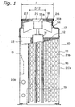
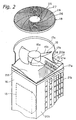
- an outdoor unit 10 (an example of a ventilation unit) of an air conditioner, in which an embodiment of the present invention has been adapted, is an top blowing model which takes in outside air from the sides, exchanges heat between the outside air taken in and refrigerant, and blows the air upward.
- the outdoor unit 10 is comprised of a casing 11, a heat exchanger 12 that is disposed inside the casing 11, a control unit 13 that faces the heat exchanger 12 and is disposed inside the casing 11, a ventilation fan 15 for taking in the outside air and blowing it out, a fan guard 18 according to one embodiment of the present invention that is fitted into the casing 11, and a compressor 19 that compresses the refrigerant.
- the casing 11 has a rectangular shaped casing main body 16 that has an opening on the top thereof, and a lid member 17 that is mounted on the open portion of the casing main body 16.
- the casing main body 16 is a member made from sheet metal formed by drawing, for example, and has outside air intake ports 21a, 21b composed of a plurality of rectangular openings in a side wall 20a that is opposite the control unit 13 and in two side walls 20b, and further has a space 22 inside thereof.
- the lid member 17 is a member that is integrally formed from plastic, and a generally cylindrical bell mouth 14 is formed thereon that extends vertically.
- the lid member 17 has a mounting portion 17a that has a rectangular outer shape and is mounted on the casing main body 16, a central portion 17b that narrows into a cylindrical shape from the mounting portion 17a and is formed by the bell mouth 14., and a circular guard attachment portion 17c that extends from the central portion 17b.
- the ventilation fan 15 is a propeller fan having a cylindrical hub 15a positioned in the center thereof, and a plurality of blades 15b provided around the circumference of the hub, and is disposed inside the bell mouth 14.
- the ventilation fan 15 is rotatively driven by a motor 31 attached to the casing main body 16.
- the fan guard 18 has a closing plate 25 positioned in the center thereof, an outer frame 26 positioned around the outer circumference thereof, a plurality of curved radiating ribs 27 (an example of the first ribs) that bind the closing plate 25 and the outer frame 26 together, and annular ribs 28 (an example of the second ribs) annularly disposed between the closing plate 25 and the outer frame 26.
- the fan guard 18 is, for example, integrally formed from plastic.
- the closing plate 25 is a circular part whose diameter is larger than that of the hub 15a of the ventilation fan 15.
- the outer frame 26 is fitted into the guard attachment portion, and the fan guard 18 is fitted into the lid member 17.
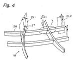
- the radiating ribs 27 are disposed such that they radiate out from the closing plate 25 to the outer frame 26 in the radial direction, and are formed such that they have a convex curve on the downstream side of the direction of rotation of the ventilation fan 15. In this way, it will be easy for the air blown from the ventilation fan 15 radially outward to follow the radiating ribs 27.
- the radiating ribs 27 each have a convex curve on the downstream side of the direction of rotation of the ventilation fan 15 such that they are trochoidal in shape.
- the radiating ribs 27 are formed such that they are slanted toward the downstream side of the direction of rotation of the ventilation fan 15 to follow the flow of the air blown out thereby. Specifically, the radiating ribs 27 are formed to slant toward the downstream side of the direction of rotation at a first angle ⁇ with respect to a first reference plane PL1 that is parallel to the axis of rotation of the ventilation fan 15.
- the range of the first angle ⁇ is preferably between 20 and 40 degrees, and more preferably in the vicinity of 30 degrees.
- the first angle a When the first angle a is in the aforementioned range, it can approach the angle at which the velocity component of the air blown in the axial direction by the ventilation fan 15 at a radial position thereon is at a maximum, and the resistance to the blown air can be more effectively reduced.
- the annular ribs 28 are concentrically disposed in the radial direction between the closing plate 25 and the outer frame 26 and are spaced apart with predetermined spacing. As shown in Figs. 1 and 3, the annular ribs 28 disposed outside a straight line D/2 that is half the outer diameter D of the outer frame 26 are formed to lean in the radial direction along the flow of the air blown by the ventilation fan 15. Specifically, the annular ribs 28 are formed to slant outward in a direction at which the air is blown out at a second angle ⁇ with respect to a cylindrical second reference plane PL2 that are concentric with the rotational axis of the ventilation fan 15. The second angle ⁇ is preferably between 5 and 15 degrees, and more preferably in the vicinity of 10 degrees.
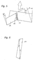
- an undercut portion UC that prevents the fan guard 18 from being taken out of a mold when formed integrally is produced at the intersection of the radiating ribs 27 and the annular ribs 28.
- the undercut portion UC is an intersecting portion that prevents the fan guard 18 from being taken out of a mold (in the direction of the arrow shown in Fig. 5) due to the fact that the ribs lean in the opposite directions.
- a built up portion 29 is formed in the undercut portion UC.
- the built up portion 29 is a four sided body composed of two right angled triangles that respectively have a first angle ⁇ and a second angle ⁇ therein.
- the built up portion 29 is formed in the two undercut portions UC on the intersecting portions.
- split molds do not have to be employed, and thus it is easy to integrally form the fan guard 18, both edges of the annular ribs 28 will be strengthened at their highest bending moment by the built up portion 29, and the resilience of the annular ribs 28 will be high. Because of this, the resilience of the entire fan guard 18 in the thickness direction will be increased.
- the heat exchanger 12 has a plurality of cooling fins, is disposed inside the casing 11 on the side walls 20a, 20b having outside air intake ports 21a, 21b, has refrigerant that flows therethrough, and exchanges heat with the air taken in. For example, during cooling, it exchanges heat between the refrigerant that was condensed in an indoor unit and the air that was taken in, and heats up the air. In addition, during heating, it exchanges heat between the air that was taken in and the compressed high temperature/high pressure refrigerant, and cools the air.
- the control unit 13 controls the compressor 19 and the ventilation fan 15 of the outdoor unit 10 in accordance with the room temperature and the operational mode.
- the compressor 19 compresses the refrigerant to a high temperature and high pressure, and during cooling, switches between a heat exchanger of the indoor unit (not shown in the figures) and the heat exchanger 12 and then transmits this refrigerant.
- the width of the annular ribs 28 (the length of the thickness of the annular ribs 28 in the direction in which they intersect) can be made longer than when they are not slanted, and the fan guard 18 can maintain its resilience in the thickness direction for a long period of time.
- built up portions 29 are formed in the undercut portions UC of the intersecting portions of the radiating ribs 27 and the annular ribs 28, the strength of both edges at the greatest bending moment of the annular ribs 28 is further increased by the built up portions 29, and resilience of the annular ribs 28 is further increased. Because of this, the resilience of the entire fan guard 18 in the thickness direction is further increased.
- the first ribs are curved in the rotational direction, and thus by curving them such that they follow the rotating divergent current of the blown air, it is difficult for the blown air to collide with the first ribs, and it is easy to eliminate resistance to the blown air.
- the second ribs are slanted in the outer radial direction such that they follow the flow of blown air, and thus it is difficult for the flow of blown air to collide with the second ribs, and there is little resistance to the flow of blown air by the second ribs. Because of this, even if first and second ribs are provided, the flow of blown air is smooth, and pressure drop and noise can be suppressed.
- the width of the second ribs (the length of the thickness of second ribs in the direction that they intersect) are longer than when they are not slanted, and the resilience of the fan guard in the thickness direction can be maintained at a high level.
- the resistance to the flow of blown air can be further reduced and pressure drop and noise can be further suppressed.
- the undercut portions can be eliminated by built up. Because of this, it is easy to remove the fan guard from a mold, and is easy to integrally form the fan guard from plastic or the like. Moreover, because the cross sectional area of the fixed portion that enlarges the highest bending moment in the second ribs is made large, the second ribs are even more resilient, and the resilience of the fan guard in the thickness direction can be maintained at an even higher level.
- the slant of the first ribs are adapted to the flow of the rotating blown air.
- the slant of the second ribs are adapted to the flow of the rotating blown air.
- the hub of the ventilation fan does not contribute to ventilation and is covered by the closing plate, and thus it is easy to prevent reverse flow from the ventilation fan.
- the curve of the first ribs is easily followed by the flow of the blown air.
- the mold for an integrally formed fan guard is easily manufactured.
- the mold for an integrally formed fan guard is easily manufactured.
Landscapes
- Engineering & Computer Science (AREA)
- Mechanical Engineering (AREA)
- General Engineering & Computer Science (AREA)
- Chemical & Material Sciences (AREA)
- Combustion & Propulsion (AREA)
- Structures Of Non-Positive Displacement Pumps (AREA)
- Other Air-Conditioning Systems (AREA)
Abstract
Description
The
Claims (11)
- A fan guard (18) of a ventilation unit (10) that is mounted in an air discharge port (17) of the ventilation unit (10) having a ventilation fan (15), the fan guard (18) comprising:an outer frame (26) mounted in the outer circumference of the air discharge port (17);a plurality of first ribs (27) that are formed such that they are curved in the rotational direction of the ventilation fan (15) and radiate outward toward the outer frame (26) in the radial direction from the vicinity of a central member of the outer frame (26); anda plurality of second ribs (28) that are integral with the first ribs (27), concentrically disposed at a predetermined spacing in the radial direction from the rotational axis of the ventilation fan (15), and formed such that those in the outer circumference are slanted toward the outer radial direction to follow the flow of blown air from the ventilation fan (15).
- The fan guard (18) of the ventilation unit (10) according to claim 1, wherein the first ribs (27) are formed such that they are slanted toward the downstream side of the rotational direction of the ventilation fan (15) to follow the flow of the air blown therefrom.
- The fan guard (18) of the ventilation unit (10) according to claim 2, wherein the first ribs (27) and the second ribs (28) are slanted at different angles, and a built up portion (29) is formed between the first ribs (27) and the second ribs (28) at the point where both ribs intersect.
- The fan guard (18) of the ventilation unit (10) according to claims 2 or 3, wherein the first ribs (27) are formed such that they are slanted toward the downstream side of the rotational direction of the ventilation fan (15) to follow the flow of the air blown therefrom at an angle of 20 to 40 degrees with respect to a first reference plane (PL1) that is parallel with the rotational axis of the ventilation fan (15).
- The fan guard (18) of the ventilation unit (10) according to claim 4, wherein the second ribs (28) are formed such that they are slanted at an angle of 5 to 15 degrees with respect to a cylindrical second reference plane (PL2) that is concentric with the rotational axis of the ventilation fan (15).
- The fan guard (18) of the ventilation unit (10) according to any of claims 1 to 5,
wherein the ventilation fan (15) is a propeller fan having a cylindrical hub (15a) positioned at the center thereof, and a plurality of blades (15b) positioned around the circumference of the hub (15a); and
further comprising a closing plate (25) disposed such that it faces the hub (15a) and is concentric with the rotational axis of the ventilation fan (15);
wherein the first ribs (27) are formed to extend from the closing plate (25) to the outer frame (26). - The fan guard (18) of the ventilation unit (10) according to claim 6, wherein the closing plate (25) has a circular shape that is larger than the diameter of the hub (15a).
- The fan guard (18) of the ventilation unit (10) according to any of claims 1 to 7, wherein the first ribs (27) are formed such that they are curved in a trochoidal curve.
- The fan guard (18) of the ventilation unit (10) according to any of claims 6 to 8, wherein the second ribs (28) are formed such that only those in the outer circumference are slanted and those in the inner circumference are not slanted.
- The fan guard (18) of the ventilation unit (10) according to claim 9, wherein the second ribs (28) in an outer circumferential region beyond 1/3 the length in the radial direction of the blades (15b) of the ventilation fan (15) are slanted.
- The fan guard (18) of the ventilation unit (10) according to claim 9, wherein the second ribs (28) in an outer circumferential region beyond 1/2 of the outer diameter of the outer frame (26) are slanted.
Applications Claiming Priority (3)
| Application Number | Priority Date | Filing Date | Title |
|---|---|---|---|
| JP2001020482 | 2001-01-29 | ||
| JP2001020482A JP3982181B2 (en) | 2001-01-29 | 2001-01-29 | Fan guard for blower unit |
| PCT/JP2002/000363 WO2002061343A1 (en) | 2001-01-29 | 2002-01-18 | Fan guard of fan unit |
Publications (3)
| Publication Number | Publication Date |
|---|---|
| EP1357337A1 true EP1357337A1 (en) | 2003-10-29 |
| EP1357337A4 EP1357337A4 (en) | 2009-06-17 |
| EP1357337B1 EP1357337B1 (en) | 2011-03-09 |
Family
ID=18886182
Family Applications (1)
| Application Number | Title | Priority Date | Filing Date |
|---|---|---|---|
| EP02715832A Expired - Lifetime EP1357337B1 (en) | 2001-01-29 | 2002-01-18 | Fan guard of fan unit |
Country Status (8)
| Country | Link |
|---|---|
| US (1) | US6764277B2 (en) |
| EP (1) | EP1357337B1 (en) |
| JP (1) | JP3982181B2 (en) |
| CN (3) | CN1275006C (en) |
| AU (1) | AU2002225445B2 (en) |
| DE (1) | DE60239387D1 (en) |
| ES (1) | ES2359393T3 (en) |
| WO (1) | WO2002061343A1 (en) |
Cited By (8)
| Publication number | Priority date | Publication date | Assignee | Title |
|---|---|---|---|---|
| EP2085709A1 (en) * | 2008-01-30 | 2009-08-05 | LG Electronics Inc. | Air conditioner |
| EP2270338A4 (en) * | 2008-04-22 | 2014-10-01 | Mitsubishi Electric Corp | BLOWER AND HEAT PUMP DEVICE USING THE SAME |
| WO2016116871A1 (en) * | 2015-01-22 | 2016-07-28 | Elica S.P.A. | Suction grid for an air guide of a domestic hood, air guide having such grid and domestic hood having such air guide. |
| EP2483604A4 (en) * | 2009-09-28 | 2017-08-23 | LG Electronics Inc. | Outdoor unit of air-conditioner |
| EP3214316A1 (en) * | 2007-02-23 | 2017-09-06 | Sew-Eurodrive GmbH & Co. KG | System and series of gears |
| CN107388424A (en) * | 2017-08-04 | 2017-11-24 | 广东美的制冷设备有限公司 | Outlet housing and air-conditioner outdoor unit |
| WO2020164795A1 (en) * | 2019-02-12 | 2020-08-20 | Sew-Eurodrive Gmbh & Co. Kg | Drive system, comprising an electric motor, a transmission and an adapter having a fan |
| EP3837473A4 (en) * | 2018-10-05 | 2021-10-13 | Samsung Electronics Co., Ltd. | Air conditioner |
Families Citing this family (41)
| Publication number | Priority date | Publication date | Assignee | Title |
|---|---|---|---|---|
| JP2004156884A (en) | 2002-11-08 | 2004-06-03 | Daikin Ind Ltd | Fan guard for blower unit |
| US7118333B2 (en) * | 2002-11-22 | 2006-10-10 | Nidec Corporation | Electric cooling fan and case of electronic or electric device |
| CA2607971A1 (en) * | 2005-05-12 | 2006-11-16 | Advantec Australasia Pty. Limited | Vent and grilles |
| US20100075588A1 (en) * | 2008-08-20 | 2010-03-25 | Haneline Ronald W | Ventilation fan |
| JP2010117044A (en) * | 2008-11-11 | 2010-05-27 | Mitsubishi Heavy Ind Ltd | Outdoor unit for air conditioner |
| CN101619885B (en) * | 2009-07-28 | 2011-10-19 | 广东志高空调有限公司 | Air outlet mesh of outdoor unit of air conditioner |
| WO2012134983A2 (en) * | 2011-03-25 | 2012-10-04 | Vornado Air, Llc | Circular grill for an air circulator unit |
| USD676124S1 (en) | 2011-04-07 | 2013-02-12 | Camair LLC | Pedestal fan parts |
| US8696305B2 (en) * | 2011-06-01 | 2014-04-15 | Deere & Company | Axial fan assembly |
| JP5441981B2 (en) * | 2011-10-26 | 2014-03-12 | 三菱電機株式会社 | Air conditioner indoor unit |
| US9631804B1 (en) * | 2012-01-27 | 2017-04-25 | Joseph Gregory Glenn | Combination fan and light attachable to a hat |
| JP6021141B2 (en) * | 2012-06-08 | 2016-11-09 | アルバック機工株式会社 | Pump device |
| CN103542468B (en) * | 2012-07-16 | 2016-07-06 | 珠海格力电器股份有限公司 | An air conditioner, an outdoor unit and its fan protection grille |
| CN102734234B (en) * | 2012-07-18 | 2016-04-20 | Tcl空调器(中山)有限公司 | Protective housing, fan component and air conditioner outdoor machine |
| DE102012109542A1 (en) * | 2012-10-08 | 2014-04-10 | Ebm-Papst Mulfingen Gmbh & Co. Kg | "Flow straightener for an axial fan" |
| US10605464B2 (en) | 2012-10-15 | 2020-03-31 | Whirlpool Corporation | Induction cooktop |
| ITTO20120896A1 (en) | 2012-10-15 | 2014-04-16 | Indesit Co Spa | INDUCTION HOB |
| US9366266B2 (en) * | 2013-03-14 | 2016-06-14 | Helen Of Troy Limited | Reconfigurable grille and fan assembly including reconfigurable grille |
| CN104930604B (en) * | 2014-03-17 | 2018-02-27 | 珠海格力电器股份有限公司 | Air outlet protection structure, air conditioner outdoor unit and design method of air outlet protection structure |
| GB2539131B (en) * | 2014-03-27 | 2018-11-28 | Trane Int Inc | Diffuser collar for a condenser fan in an HVAC system |
| JP6505443B2 (en) * | 2015-01-15 | 2019-04-24 | シャープ株式会社 | Outdoor unit fan guard |
| CN107923413B (en) * | 2015-08-10 | 2020-12-01 | 三菱电机株式会社 | Blowers and Air Conditioners |
| US10514046B2 (en) | 2015-10-09 | 2019-12-24 | Carrier Corporation | Air management system for the outdoor unit of a residential air conditioner or heat pump |
| KR102489427B1 (en) * | 2016-05-31 | 2023-01-18 | 삼성전자주식회사 | Fan guard assembly and outdoor unit having the same |
| WO2018066085A1 (en) * | 2016-10-05 | 2018-04-12 | 三菱電機株式会社 | Outdoor unit of air conditioner |
| WO2018131183A1 (en) * | 2017-01-10 | 2018-07-19 | 三菱電機株式会社 | Blower and air conditioning device |
| EP3432682B1 (en) | 2017-07-18 | 2026-04-08 | Whirlpool Corporation | Method for operating an induction cooking hob and cooking hob using such method |
| CN207122442U (en) | 2017-08-18 | 2018-03-20 | 开利公司 | Fan casing and there is its air-conditioner set |
| US10993292B2 (en) | 2017-10-23 | 2021-04-27 | Whirlpool Corporation | System and method for tuning an induction circuit |
| US12588112B2 (en) | 2018-04-23 | 2026-03-24 | Whirlpool Corporation | System and method for controlling induction heating devices with series connected switching devices |
| US11140751B2 (en) | 2018-04-23 | 2021-10-05 | Whirlpool Corporation | System and method for controlling quasi-resonant induction heating devices |
| US12302478B2 (en) | 2018-04-23 | 2025-05-13 | Whirlpool Corporation | Control circuits and methods for distributed induction heating devices |
| US11708980B2 (en) | 2019-04-02 | 2023-07-25 | Brock Amundson | Heat exchanger protective cover |
| CN109974141B (en) * | 2019-04-08 | 2024-07-26 | 广东美的暖通设备有限公司 | Air outlet grille of air conditioner and air conditioner |
| WO2021086342A1 (en) * | 2019-10-30 | 2021-05-06 | Hewlett-Packard Development Company, L.P. | Guards for air-moving devices |
| CN111457572A (en) * | 2020-04-09 | 2020-07-28 | 珠海格力电器股份有限公司 | Air Duct Components and Air Conditioners |
| CN111878900B (en) * | 2020-08-24 | 2024-12-31 | 珠海格力电器股份有限公司 | Air outlet device and air disinfection machine |
| CN115493212B (en) * | 2021-06-17 | 2025-02-18 | 宁波奥克斯电气有限公司 | Outer machine shell of air conditioner and outer machine of air conditioner |
| CN113834137B (en) * | 2021-09-24 | 2022-12-13 | 珠海格力电器股份有限公司 | Air outlet grille, air conditioner outdoor unit and air conditioner |
| JP7755478B2 (en) * | 2021-12-17 | 2025-10-16 | シャープ株式会社 | dehumidifier |
| CN116838655B (en) * | 2023-07-25 | 2025-12-12 | 四川长虹空调有限公司 | Fan Protective Cover Design Method |
Family Cites Families (24)
| Publication number | Priority date | Publication date | Assignee | Title |
|---|---|---|---|---|
| JPS54100135A (en) * | 1978-01-25 | 1979-08-07 | Toshiba Corp | Air conditioner |
| JPS6045812B2 (en) | 1979-07-04 | 1985-10-12 | 旭光学工業株式会社 | Repetitive time-division digital photometer |
| JPS5827348Y2 (en) * | 1979-07-05 | 1983-06-14 | 松下電器産業株式会社 | Fan guard for air conditioners, etc. |
| JPS58131382A (en) | 1982-01-29 | 1983-08-05 | Toshiba Corp | Cryosorption pump |
| JPS58131382U (en) * | 1982-03-01 | 1983-09-05 | 株式会社東芝 | Air conditioner fan guard |
| JPS6062567A (en) * | 1984-07-30 | 1985-04-10 | 株式会社日立製作所 | Outdoor unit for air conditioner |
| JPS6196268A (en) | 1984-10-15 | 1986-05-14 | Mitsubishi Heavy Ind Ltd | Closing-valve apparatus for annular flow-passage having penetration part inside |
| JPH0243016Y2 (en) * | 1984-11-29 | 1990-11-15 | ||
| JPS6122165A (en) * | 1985-06-17 | 1986-01-30 | 株式会社日立製作所 | Outdoor unit for air conditioner |
| US5118252A (en) * | 1990-05-24 | 1992-06-02 | The W. B. Marvin Manufacturing Company | Intake grill for electric fan assembly |
| JP2924352B2 (en) * | 1991-09-17 | 1999-07-26 | 松下電器産業株式会社 | Front grill for outdoor unit of air conditioner |
| JPH0799981B2 (en) * | 1992-08-11 | 1995-11-01 | 實 豊根 | Low tannin implant material and its manufacturing method |
| JPH06257795A (en) * | 1993-03-02 | 1994-09-16 | Matsushita Electric Ind Co Ltd | Front grill for air conditioner outdoor device |
| US5466120A (en) | 1993-03-30 | 1995-11-14 | Nippondenso Co., Ltd. | Blower with bent stays |
| JP3227552B2 (en) * | 1994-07-28 | 2001-11-12 | 松下電器産業株式会社 | Blower safety cover |
| JP3325746B2 (en) * | 1995-05-31 | 2002-09-17 | 出光石油化学株式会社 | Plastic pallets |
| JPH10205497A (en) * | 1996-11-21 | 1998-08-04 | Zexel Corp | Cooling air introducing/discharging device |
| DE19753373A1 (en) * | 1996-12-10 | 1998-06-25 | Papst Motoren Gmbh & Co Kg | Housing for axial cooling fan for EMC-screened apparatus, such as CPU |
| JPH10197014A (en) * | 1997-01-06 | 1998-07-31 | Matsushita Refrig Co Ltd | Outdoor machine of air conditioner |
| JPH10332190A (en) * | 1997-05-30 | 1998-12-15 | Mitsubishi Electric Corp | Cold air outlet |
| US6101459A (en) * | 1997-08-15 | 2000-08-08 | Compaq Computer Corporation | System and associated method for cooling components within a computer system |
| JP4380105B2 (en) * | 1999-08-09 | 2009-12-09 | ダイキン工業株式会社 | Fan guard and air conditioner for blower unit |
| US6257501B1 (en) * | 2000-09-05 | 2001-07-10 | Atico International Usa, Inc. | Electric fan having a concentric fan-mounted mister |
| US6435889B1 (en) * | 2000-12-29 | 2002-08-20 | Compaq Information Technologies Group, L.P. | Reduced complexity hot plug blind mate fan assembly and connector therefor |
-
2001
- 2001-01-29 JP JP2001020482A patent/JP3982181B2/en not_active Expired - Lifetime
-
2002
- 2002-01-18 ES ES02715832T patent/ES2359393T3/en not_active Expired - Lifetime
- 2002-01-18 EP EP02715832A patent/EP1357337B1/en not_active Expired - Lifetime
- 2002-01-18 WO PCT/JP2002/000363 patent/WO2002061343A1/en not_active Ceased
- 2002-01-18 AU AU2002225445A patent/AU2002225445B2/en not_active Ceased
- 2002-01-18 DE DE60239387T patent/DE60239387D1/en not_active Expired - Lifetime
- 2002-01-18 US US10/257,042 patent/US6764277B2/en not_active Expired - Fee Related
- 2002-01-25 CN CNB2004101001440A patent/CN1275006C/en not_active Expired - Fee Related
- 2002-01-25 CN CN02202160U patent/CN2526721Y/en not_active Expired - Lifetime
- 2002-01-25 CN CNB021028443A patent/CN1207520C/en not_active Expired - Fee Related
Cited By (10)
| Publication number | Priority date | Publication date | Assignee | Title |
|---|---|---|---|---|
| EP3214316A1 (en) * | 2007-02-23 | 2017-09-06 | Sew-Eurodrive GmbH & Co. KG | System and series of gears |
| EP2085709A1 (en) * | 2008-01-30 | 2009-08-05 | LG Electronics Inc. | Air conditioner |
| EP2270338A4 (en) * | 2008-04-22 | 2014-10-01 | Mitsubishi Electric Corp | BLOWER AND HEAT PUMP DEVICE USING THE SAME |
| EP2483604A4 (en) * | 2009-09-28 | 2017-08-23 | LG Electronics Inc. | Outdoor unit of air-conditioner |
| WO2016116871A1 (en) * | 2015-01-22 | 2016-07-28 | Elica S.P.A. | Suction grid for an air guide of a domestic hood, air guide having such grid and domestic hood having such air guide. |
| EP3247952B1 (en) | 2015-01-22 | 2019-03-20 | Elica S.p.A. | Suction grid for an air guide of a domestic hood, air guide having such grid and domestic hood having such air guide |
| CN107388424A (en) * | 2017-08-04 | 2017-11-24 | 广东美的制冷设备有限公司 | Outlet housing and air-conditioner outdoor unit |
| EP3837473A4 (en) * | 2018-10-05 | 2021-10-13 | Samsung Electronics Co., Ltd. | Air conditioner |
| US11466873B2 (en) | 2018-10-05 | 2022-10-11 | Samsung Electronics Co., Ltd. | Air conditioner |
| WO2020164795A1 (en) * | 2019-02-12 | 2020-08-20 | Sew-Eurodrive Gmbh & Co. Kg | Drive system, comprising an electric motor, a transmission and an adapter having a fan |
Also Published As
| Publication number | Publication date |
|---|---|
| ES2359393T3 (en) | 2011-05-23 |
| CN1368624A (en) | 2002-09-11 |
| JP3982181B2 (en) | 2007-09-26 |
| WO2002061343A1 (en) | 2002-08-08 |
| JP2002228192A (en) | 2002-08-14 |
| CN1207520C (en) | 2005-06-22 |
| CN1275006C (en) | 2006-09-13 |
| EP1357337B1 (en) | 2011-03-09 |
| CN1670439A (en) | 2005-09-21 |
| US6764277B2 (en) | 2004-07-20 |
| US20030138321A1 (en) | 2003-07-24 |
| AU2002225445B2 (en) | 2004-01-15 |
| EP1357337A4 (en) | 2009-06-17 |
| CN2526721Y (en) | 2002-12-18 |
| DE60239387D1 (en) | 2011-04-21 |
Similar Documents
| Publication | Publication Date | Title |
|---|---|---|
| AU2002225445B2 (en) | Fan guard of fan unit | |
| US7172387B2 (en) | Fan guard for blower unit | |
| KR100713996B1 (en) | Blade wheel for centrifugal blower and centrifugal blower with the same | |
| JP6401727B2 (en) | Outdoor unit for blower and air conditioner | |
| EP1120571B1 (en) | Fan guard of blower unit and air conditioner | |
| JP3843941B2 (en) | Centrifugal blower | |
| WO2017042877A1 (en) | Propeller fan, propeller fan device and outdoor unit for air conditioning device | |
| JP2004218450A (en) | Centrifugal blower | |
| AU2017410135B2 (en) | Propeller fan and outdoor unit for air-conditioning apparatus | |
| JP3635819B2 (en) | Centrifugal fan and air conditioner equipped with this centrifugal fan | |
| WO2017042865A1 (en) | Outdoor unit for air conditioner | |
| US20240183358A1 (en) | Air blowing device and air conditioning system including same | |
| CN119914948A (en) | Air conditioner with grille | |
| JP2007205268A (en) | Centrifugal fan | |
| JPH10252689A (en) | Cross flow fan and air conditioner with cross flow fan | |
| KR100329928B1 (en) | Outdoor unit for a split-type air conditioner | |
| JP2005016457A (en) | Blower and heat exchange unit equipped with a blower | |
| JP3846468B2 (en) | Turbo fan | |
| JP2018025357A (en) | Indoor unit and air conditioner | |
| CN210511938U (en) | A kind of air conditioner outdoor unit fan cover and air conditioner | |
| KR20060081223A (en) | Air conditioner turbofan | |
| WO2023223383A1 (en) | Cross flow fan, blowing device, and refrigeration cycle device | |
| WO2026100416A1 (en) | Centrifugal fan and air conditioner comprising same | |
| WO2023112077A1 (en) | Axial fan, blower, and refrigeration cycle device | |
| JP2026081877A (en) | Centrifugal fan and air conditioner equipped therewith |
Legal Events
| Date | Code | Title | Description |
|---|---|---|---|
| PUAI | Public reference made under article 153(3) epc to a published international application that has entered the european phase |
Free format text: ORIGINAL CODE: 0009012 |
|
| 17P | Request for examination filed |
Effective date: 20021018 |
|
| AK | Designated contracting states |
Kind code of ref document: A1 Designated state(s): AT BE CH CY DE DK ES FI FR GB GR IE IT LI LU MC NL PT SE TR |
|
| A4 | Supplementary search report drawn up and despatched |
Effective date: 20090518 |
|
| RIC1 | Information provided on ipc code assigned before grant |
Ipc: F04D 29/70 20060101ALI20090512BHEP Ipc: F24F 5/00 20060101AFI20020813BHEP |
|
| 17Q | First examination report despatched |
Effective date: 20090904 |
|
| RIC1 | Information provided on ipc code assigned before grant |
Ipc: F24F 5/00 20060101AFI20100728BHEP Ipc: F04D 29/70 20060101ALI20100728BHEP |
|
| GRAP | Despatch of communication of intention to grant a patent |
Free format text: ORIGINAL CODE: EPIDOSNIGR1 |
|
| RBV | Designated contracting states (corrected) |
Designated state(s): BE DE ES FR GB IT |
|
| GRAS | Grant fee paid |
Free format text: ORIGINAL CODE: EPIDOSNIGR3 |
|
| GRAA | (expected) grant |
Free format text: ORIGINAL CODE: 0009210 |
|
| AK | Designated contracting states |
Kind code of ref document: B1 Designated state(s): BE DE ES FR GB IT |
|
| REG | Reference to a national code |
Ref country code: GB Ref legal event code: FG4D |
|
| REF | Corresponds to: |
Ref document number: 60239387 Country of ref document: DE Date of ref document: 20110421 Kind code of ref document: P |
|
| REG | Reference to a national code |
Ref country code: DE Ref legal event code: R096 Ref document number: 60239387 Country of ref document: DE Effective date: 20110421 |
|
| REG | Reference to a national code |
Ref country code: ES Ref legal event code: FG2A Ref document number: 2359393 Country of ref document: ES Kind code of ref document: T3 Effective date: 20110523 |
|
| PG25 | Lapsed in a contracting state [announced via postgrant information from national office to epo] |
Ref country code: BE Free format text: LAPSE BECAUSE OF FAILURE TO SUBMIT A TRANSLATION OF THE DESCRIPTION OR TO PAY THE FEE WITHIN THE PRESCRIBED TIME-LIMIT Effective date: 20110309 |
|
| PLBE | No opposition filed within time limit |
Free format text: ORIGINAL CODE: 0009261 |
|
| STAA | Information on the status of an ep patent application or granted ep patent |
Free format text: STATUS: NO OPPOSITION FILED WITHIN TIME LIMIT |
|
| 26N | No opposition filed |
Effective date: 20111212 |
|
| REG | Reference to a national code |
Ref country code: DE Ref legal event code: R097 Ref document number: 60239387 Country of ref document: DE Effective date: 20111212 |
|
| PGFP | Annual fee paid to national office [announced via postgrant information from national office to epo] |
Ref country code: FR Payment date: 20120202 Year of fee payment: 11 |
|
| PGFP | Annual fee paid to national office [announced via postgrant information from national office to epo] |
Ref country code: DE Payment date: 20120111 Year of fee payment: 11 |
|
| PGFP | Annual fee paid to national office [announced via postgrant information from national office to epo] |
Ref country code: IT Payment date: 20120119 Year of fee payment: 11 Ref country code: GB Payment date: 20120118 Year of fee payment: 11 |
|
| PGFP | Annual fee paid to national office [announced via postgrant information from national office to epo] |
Ref country code: ES Payment date: 20120127 Year of fee payment: 11 |
|
| GBPC | Gb: european patent ceased through non-payment of renewal fee |
Effective date: 20130118 |
|
| REG | Reference to a national code |
Ref country code: FR Ref legal event code: ST Effective date: 20130930 |
|
| PG25 | Lapsed in a contracting state [announced via postgrant information from national office to epo] |
Ref country code: DE Free format text: LAPSE BECAUSE OF NON-PAYMENT OF DUE FEES Effective date: 20130801 |
|
| REG | Reference to a national code |
Ref country code: DE Ref legal event code: R119 Ref document number: 60239387 Country of ref document: DE Effective date: 20130801 |
|
| PG25 | Lapsed in a contracting state [announced via postgrant information from national office to epo] |
Ref country code: GB Free format text: LAPSE BECAUSE OF NON-PAYMENT OF DUE FEES Effective date: 20130118 Ref country code: FR Free format text: LAPSE BECAUSE OF NON-PAYMENT OF DUE FEES Effective date: 20130131 |
|
| PG25 | Lapsed in a contracting state [announced via postgrant information from national office to epo] |
Ref country code: IT Free format text: LAPSE BECAUSE OF NON-PAYMENT OF DUE FEES Effective date: 20130118 |
|
| REG | Reference to a national code |
Ref country code: ES Ref legal event code: FD2A Effective date: 20140509 |
|
| PG25 | Lapsed in a contracting state [announced via postgrant information from national office to epo] |
Ref country code: ES Free format text: LAPSE BECAUSE OF NON-PAYMENT OF DUE FEES Effective date: 20130119 |