EP1357298A2 - Actuation valve for a double-acting pneumatic cylinder and use of such a valve for a pneumatic-cylinder actuated creel - Google Patents
Actuation valve for a double-acting pneumatic cylinder and use of such a valve for a pneumatic-cylinder actuated creel Download PDFInfo
- Publication number
- EP1357298A2 EP1357298A2 EP03008338A EP03008338A EP1357298A2 EP 1357298 A2 EP1357298 A2 EP 1357298A2 EP 03008338 A EP03008338 A EP 03008338A EP 03008338 A EP03008338 A EP 03008338A EP 1357298 A2 EP1357298 A2 EP 1357298A2
- Authority
- EP
- European Patent Office
- Prior art keywords
- valve
- compressed air
- chamber
- valves
- pneumatic cylinder
- Prior art date
- Legal status (The legal status is an assumption and is not a legal conclusion. Google has not performed a legal analysis and makes no representation as to the accuracy of the status listed.)
- Granted
Links
Images


Classifications
-
- F—MECHANICAL ENGINEERING; LIGHTING; HEATING; WEAPONS; BLASTING
- F15—FLUID-PRESSURE ACTUATORS; HYDRAULICS OR PNEUMATICS IN GENERAL
- F15B—SYSTEMS ACTING BY MEANS OF FLUIDS IN GENERAL; FLUID-PRESSURE ACTUATORS, e.g. SERVOMOTORS; DETAILS OF FLUID-PRESSURE SYSTEMS, NOT OTHERWISE PROVIDED FOR
- F15B11/00—Servomotor systems without provision for follow-up action; Circuits therefor
- F15B11/003—Systems with load-holding valves
-
- B—PERFORMING OPERATIONS; TRANSPORTING
- B65—CONVEYING; PACKING; STORING; HANDLING THIN OR FILAMENTARY MATERIAL
- B65H—HANDLING THIN OR FILAMENTARY MATERIAL, e.g. SHEETS, WEBS, CABLES
- B65H49/00—Unwinding or paying-out filamentary material; Supporting, storing or transporting packages from which filamentary material is to be withdrawn or paid-out
- B65H49/02—Methods or apparatus in which packages do not rotate
- B65H49/04—Package-supporting devices
- B65H49/14—Package-supporting devices for several operative packages
- B65H49/16—Stands or frameworks
-
- B—PERFORMING OPERATIONS; TRANSPORTING
- B65—CONVEYING; PACKING; STORING; HANDLING THIN OR FILAMENTARY MATERIAL
- B65H—HANDLING THIN OR FILAMENTARY MATERIAL, e.g. SHEETS, WEBS, CABLES
- B65H2701/00—Handled material; Storage means
- B65H2701/30—Handled filamentary material
- B65H2701/31—Textiles threads or artificial strands of filaments
-
- F—MECHANICAL ENGINEERING; LIGHTING; HEATING; WEAPONS; BLASTING
- F15—FLUID-PRESSURE ACTUATORS; HYDRAULICS OR PNEUMATICS IN GENERAL
- F15B—SYSTEMS ACTING BY MEANS OF FLUIDS IN GENERAL; FLUID-PRESSURE ACTUATORS, e.g. SERVOMOTORS; DETAILS OF FLUID-PRESSURE SYSTEMS, NOT OTHERWISE PROVIDED FOR
- F15B2211/00—Circuits for servomotor systems
- F15B2211/30—Directional control
- F15B2211/305—Directional control characterised by the type of valves
- F15B2211/30505—Non-return valves, i.e. check valves
- F15B2211/3051—Cross-check valves
-
- F—MECHANICAL ENGINEERING; LIGHTING; HEATING; WEAPONS; BLASTING
- F15—FLUID-PRESSURE ACTUATORS; HYDRAULICS OR PNEUMATICS IN GENERAL
- F15B—SYSTEMS ACTING BY MEANS OF FLUIDS IN GENERAL; FLUID-PRESSURE ACTUATORS, e.g. SERVOMOTORS; DETAILS OF FLUID-PRESSURE SYSTEMS, NOT OTHERWISE PROVIDED FOR
- F15B2211/00—Circuits for servomotor systems
- F15B2211/30—Directional control
- F15B2211/305—Directional control characterised by the type of valves
- F15B2211/3056—Assemblies of multiple valves
- F15B2211/30565—Assemblies of multiple valves having multiple valves for a single output member, e.g. for creating higher valve function by use of multiple valves like two 2/2-valves replacing a 5/3-valve
- F15B2211/3057—Assemblies of multiple valves having multiple valves for a single output member, e.g. for creating higher valve function by use of multiple valves like two 2/2-valves replacing a 5/3-valve having two valves, one for each port of a double-acting output member
-
- F—MECHANICAL ENGINEERING; LIGHTING; HEATING; WEAPONS; BLASTING
- F15—FLUID-PRESSURE ACTUATORS; HYDRAULICS OR PNEUMATICS IN GENERAL
- F15B—SYSTEMS ACTING BY MEANS OF FLUIDS IN GENERAL; FLUID-PRESSURE ACTUATORS, e.g. SERVOMOTORS; DETAILS OF FLUID-PRESSURE SYSTEMS, NOT OTHERWISE PROVIDED FOR
- F15B2211/00—Circuits for servomotor systems
- F15B2211/30—Directional control
- F15B2211/315—Directional control characterised by the connections of the valve or valves in the circuit
- F15B2211/3157—Directional control characterised by the connections of the valve or valves in the circuit being connected to a pressure source, an output member and a return line
- F15B2211/31576—Directional control characterised by the connections of the valve or valves in the circuit being connected to a pressure source, an output member and a return line having a single pressure source and a single output member
-
- F—MECHANICAL ENGINEERING; LIGHTING; HEATING; WEAPONS; BLASTING
- F15—FLUID-PRESSURE ACTUATORS; HYDRAULICS OR PNEUMATICS IN GENERAL
- F15B—SYSTEMS ACTING BY MEANS OF FLUIDS IN GENERAL; FLUID-PRESSURE ACTUATORS, e.g. SERVOMOTORS; DETAILS OF FLUID-PRESSURE SYSTEMS, NOT OTHERWISE PROVIDED FOR
- F15B2211/00—Circuits for servomotor systems
- F15B2211/30—Directional control
- F15B2211/32—Directional control characterised by the type of actuation
- F15B2211/327—Directional control characterised by the type of actuation electrically or electronically
-
- F—MECHANICAL ENGINEERING; LIGHTING; HEATING; WEAPONS; BLASTING
- F15—FLUID-PRESSURE ACTUATORS; HYDRAULICS OR PNEUMATICS IN GENERAL
- F15B—SYSTEMS ACTING BY MEANS OF FLUIDS IN GENERAL; FLUID-PRESSURE ACTUATORS, e.g. SERVOMOTORS; DETAILS OF FLUID-PRESSURE SYSTEMS, NOT OTHERWISE PROVIDED FOR
- F15B2211/00—Circuits for servomotor systems
- F15B2211/30—Directional control
- F15B2211/32—Directional control characterised by the type of actuation
- F15B2211/329—Directional control characterised by the type of actuation actuated by fluid pressure
-
- F—MECHANICAL ENGINEERING; LIGHTING; HEATING; WEAPONS; BLASTING
- F15—FLUID-PRESSURE ACTUATORS; HYDRAULICS OR PNEUMATICS IN GENERAL
- F15B—SYSTEMS ACTING BY MEANS OF FLUIDS IN GENERAL; FLUID-PRESSURE ACTUATORS, e.g. SERVOMOTORS; DETAILS OF FLUID-PRESSURE SYSTEMS, NOT OTHERWISE PROVIDED FOR
- F15B2211/00—Circuits for servomotor systems
- F15B2211/30—Directional control
- F15B2211/35—Directional control combined with flow control
- F15B2211/353—Flow control by regulating means in return line, i.e. meter-out control
-
- F—MECHANICAL ENGINEERING; LIGHTING; HEATING; WEAPONS; BLASTING
- F15—FLUID-PRESSURE ACTUATORS; HYDRAULICS OR PNEUMATICS IN GENERAL
- F15B—SYSTEMS ACTING BY MEANS OF FLUIDS IN GENERAL; FLUID-PRESSURE ACTUATORS, e.g. SERVOMOTORS; DETAILS OF FLUID-PRESSURE SYSTEMS, NOT OTHERWISE PROVIDED FOR
- F15B2211/00—Circuits for servomotor systems
- F15B2211/40—Flow control
- F15B2211/405—Flow control characterised by the type of flow control means or valve
- F15B2211/40507—Flow control characterised by the type of flow control means or valve with constant throttles or orifices
-
- F—MECHANICAL ENGINEERING; LIGHTING; HEATING; WEAPONS; BLASTING
- F15—FLUID-PRESSURE ACTUATORS; HYDRAULICS OR PNEUMATICS IN GENERAL
- F15B—SYSTEMS ACTING BY MEANS OF FLUIDS IN GENERAL; FLUID-PRESSURE ACTUATORS, e.g. SERVOMOTORS; DETAILS OF FLUID-PRESSURE SYSTEMS, NOT OTHERWISE PROVIDED FOR
- F15B2211/00—Circuits for servomotor systems
- F15B2211/40—Flow control
- F15B2211/46—Control of flow in the return line, i.e. meter-out control
-
- F—MECHANICAL ENGINEERING; LIGHTING; HEATING; WEAPONS; BLASTING
- F15—FLUID-PRESSURE ACTUATORS; HYDRAULICS OR PNEUMATICS IN GENERAL
- F15B—SYSTEMS ACTING BY MEANS OF FLUIDS IN GENERAL; FLUID-PRESSURE ACTUATORS, e.g. SERVOMOTORS; DETAILS OF FLUID-PRESSURE SYSTEMS, NOT OTHERWISE PROVIDED FOR
- F15B2211/00—Circuits for servomotor systems
- F15B2211/70—Output members, e.g. hydraulic motors or cylinders or control therefor
- F15B2211/71—Multiple output members, e.g. multiple hydraulic motors or cylinders
- F15B2211/7107—Multiple output members, e.g. multiple hydraulic motors or cylinders the output members being mechanically linked
Definitions
- the invention relates to an actuating valve according to the preamble of the claim 1.
- Such an actuating valve is required that after the respective actuated switching valve of the pneumatic cylinder or its piston on both sides remains pressurized so that when the previously operated valve is released no further venting or pressure relief of both pressure chambers takes place, the pneumatic cylinder is held in place, d. i.e., a two-sided effective pneumatic cylinder should preferably by means of manually operated switching valves moved to its respective end positions and immediately when the actuation ceases can be stopped in its feed motion.
- This basic task is carried out e.g. B. by a conventional cylinder control a 5/3-way slide valve that can be controlled by means of two switching valves with a downstream one Exhaust air throttling solved. 3/2-way slide valves are generally used as switching valves used. This leads in particular through the use a 5/3-way slide valve due to the considerable number of required Lip seals for sealing problems between the individual valve channels to problems.
- the invention has for its object to provide an actuating valve which does not have the disadvantages, in particular through the use of a 5/3-way slide valve are required.
- an actuating valve according to the invention Claim 1 or claim 3 proposed.
- a central idea of the invention is in it, instead of the 5/3-way slide valve previously used, two 3/2-way valves to be used, which considerably reduces the sealing problems become.
- the actuating valve according to the invention is preferred for a creel for textile machines according to one or more of the claims 11-20 used.
- Figure 2 shows a double-acting pneumatic cylinder 8, in the opposite Compressed air connecting lines connected to an actuating valve 23 Merge onto L6, R6.
- An attached to the piston rod 8.1 Piston (not shown) can be connected through the compressed air connection line L6 or R6 are pressurized with compressed air while the opposite cylinder or pressure chamber is vented via the other line R6 or L6.
- a pivot bearing eye 24 is attached to the Pneumatic cylinder 8.
- Another one Swivel bearing eye 25 is attached to the piston rod 8.1 around the pneumatic cylinder to be articulated on two machine parts that are movable relative to each other.
- Figure 1a shows the actuating valve 23 in the rest position
- Figure 1b shows one Operating position in which the piston rod 8.1 in the direction of arrow f1 in the Cylinder 8 is retracted.
- FIG. 1a are to a compressed air source P by means of connecting lines L2, R2 two switching valves in the form of, for example, manually operated 3/2-way valves L1, R1 connected.
- Line branches connect to the switching valves L1, R1 L3, R3 on, which contain check valves L4, R4 and two 3/2-way valves L5, R5 lead via lines L6, R6 to the pressure chambers 8.3, 8.4 of the pneumatic cylinder 8 are connected or can be connected.
- the same The purpose is to adjust the 3/2-way valve L5 against the force of the Return spring R8 the control line R7.
- the switching valves L1, R1 as well as the check valves L4, R4 and the valves L5, R5 are preferably seat valves that have valve bodies equipped with sealing rings, which act against spring force are movable in valve chambers, the corresponding valve seats for the sealing rings to have.
- the actuating valve according to the invention thus combines schematically four separate 3/2-way valves and two check valves, preferably as Seat valves are formed and linked together so that at z.
- Actuating valve 23 shown is characterized in that the of Figures 1a and 1b described valve or control elements to save space are housed in a compact valve block.
- this valve block consists of a lower part 25 and a Upper part 26. A guided through the upper part 26 and connectable to a compressed air source P. Channel 27 opens into a distribution chamber 28.
- the lower part 25 are two valve bodies 31, 31 'mounted or guided against by means of buttons L9, R9 the force of return springs 33, 33 'can be inserted into the distribution chamber 28 are.
- the valve body 31 is formed by means of a valve stem 31.1 Annular gap in a bore 25.1 of the valve block lower part 25 mounted in such a way that the section of the bore 25.1 located above the valve stem 31.1 is open to the environment, as shown in Figure 3 for the button L9, see guide shaft 31.1 'and bore 25.1'.
- a bore section 25.4 and a valve chamber are connected to the bore 25.1 25.2, in which a push-button supported on both sides when the button R9 is pressed Sealing ring 31.2 of the valve body 31 is sealingly guided.
- the diameter of the bore section 25.4 is larger than the diameter of the valve chamber 25.2 such that the sealing ring in the bore section when the switching valve is not actuated 25.4 is housed that laterally on this sealing ring 31.2 made a connection between the channel 35 and the environment is.
- the valve chamber 25.2 opens into the forming a valve seat 25.3 Distributor chamber 28.
- the valve chamber 25.2 closes above the sealing ring 31.2 a channel 35 on the side.
- a sealing ring 31.4 of the valve body 31 is in the rest position by the spring 33 pressed against the valve seat 25.3, as in Figure 3 for the valve body 31 'is shown.
- a stepped bore which is a double valve unit consisting of a first, lower valve body 36 and a second, upper valve body 38.
- This step hole has a guide section 39 adjoining the channel 35 and adjoining it a valve chamber 41 connects to form a valve seat 40.
- Valve chamber 41 closes a valve chamber via a further valve seat 42 43 to which a valve chamber 45 is connected via a valve seat 44 is, in which a ventilation channel 46 opens laterally.
- the valve body 36 has a valve stem guided in the guide bore 39 36.1, which has a plurality of axial slots 36.2 distributed over its circumference.
- a sealing ring 36.3 At the On top of the valve stem 36.1 is a sealing ring 36.3, which is in the rest position supported by that between the lower and upper valve bodies 36, 38 Return spring 36.4 is pressed against the valve seat 40.
- the valve body 38 has a valve stem guided in the valve chamber 41 38.1, which is essentially a hollow cylinder with side wall openings 38.2 is formed and with its interior with the valve chamber 41 in connection can stand.
- This valve body 38 carries a first, lower sealing ring 38.3 to interact with the valve seat 42 and a second, upper Sealing ring 38.4 for interaction with the valve seat 44.
- the valve body 38 is also guided with a seal in the valve chamber 45 Provide piston 38.5.
- the actuating valve contains, in addition to that in connection with the valve bodies 31, 36 and 38 described a second valve unit, constructed symmetrically thereto Valve unit, the individual parts of which are shown in FIG. 3 on the left and the same reference numerals like the valve unit shown on the right in Figure 3, whereby for this valve unit shown on the left has a superscript index line is added.
- the two valve units correspond to the control lines L7, R7 of the figures 1a and 1b by means of control channels 47 and 35 '35' 47 'linked together.
- valve unit shown on the right in FIG actuated.
- the sealing ring 31.4 of the valve body 31 of lifted the valve seat 25.3 facing the distribution chamber 28, so that Compressed air flows into the channel 35 and the guide bore 39.
- This valve chamber 43 also has a lateral opening 43.1 a connection channel 50 in connection to which the leading to the pressure chamber 8.4 Compressed air connection line R6 is connected so that the compressed air in this pressure chamber 8.4 can flow.
- the lower valve body 36 After release of the button L9, the lower valve body 36 is released by the return spring 36.4 pressed down so that the sealing ring 36.3 against the valve seat 40 is pressed.
- valve body 36 of the valve unit shown on the right To the one hand the valve body 36 of the valve unit shown on the right and thus to be able to adjust the sealing ring 36.3 against the valve seat 30 and on the other hand the valve body 38 'of the valve unit shown on the left and so that the valve seal 38.4 'move against the valve seat 44'
- the textile machine 1 which is only indicated schematically in FIG. 7, is concerned for example around a cable spindles on both sides in the machine longitudinal direction equipped cabling machine.
- this is the left side of the machine assigned coil gate 2 is shown in its upper operating position.
- the the creel 2 assigned to the right machine side is in its lower loading or mounting position shown.
- each creel is 2 designed as a double coil creel and equipped with four supply coils Sp or loaded, so that two adjacent cabling spindles of a single Coil creel can be operated.
- the supply spools Sp are around so-called single supply spools for the outer thread of the cabling process.
- each creel 2 is on the top of the cabling machine 1 a carrier 3 running in the longitudinal direction of the machine by means of a holder 4 attached.
- the fixed link of a four-bar bracket 4 two further, opposing links 5 and 6 are articulated, on their Ends, opposite to the bracket 4, the fourth four-bar link 7 articulated is.
- the fixed four-bar link Bracket 4 consisting of two frame parts 4.1 which are located opposite one another at a distance between which an upper axis 4.2 and a lower axis 4.3 are mounted.
- the Four-bar link 7 is box-shaped with two opposite side walls 7.1 formed by an end wall 7.4. connected with each other are and between which an upper axis 7.2 and a lower, shown in dashed lines Axis 7.3 are stored.
- the four-bar link 5 can be pivoted on the two upper axes 4.2 and 7.2 stored.
- the four-bar link 6 mounted on the lower axes 4.3 or 7.3 the shape of a box profile for reasons of stability.
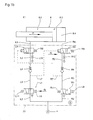
- Gas spring 9 can be pivoted on the axes 4.3 and 7.2 (see FIG. 9) stored.
- the gas pressure spring 9 by definition consists of a cylinder in the a piston rod 9.1 with possibly attached pistons for biasing the existing gas volume is retractable in the closed cylinder chamber.
- Each pneumatic cylinder 8 is preferably operated by an actuating valve driven type described.
- Each pneumatic cylinder 8 can be pressurized with compressed air on both sides Pneumatic cylinder designed and contains two by a piston from each other separate compressed air chambers, which are alternately pressurized with compressed air can.
- FIG. 8 there is a frame on the end wall 7.4 forming a mounting plate 11 attached, the two on each side receiving members 12 for supply spools Sp wears.
- An actuating valve is provided on the front of each central web 11 Via compressed air lines, not shown, on the one hand to a compressed air source and on the other hand connected to the two pressure chambers of the pneumatic cylinder 8 is.
- the Compressed air cylinder 8 is pressurized with compressed air such that its piston rod 8.1 (see FIG. 7) with the piston attached to it moves into the cylinder chamber.
- the gas pressure spring 9 at the same time by retracting the piston rod 9.1 biased.
Abstract
Description
Die Erfindung betrifft ein Betätigungsventil gemäß dem Oberbegriff des Patentanspruchs
1.The invention relates to an actuating valve according to the preamble of the
Von einem derartigen Betätigungsventil wird verlangt, daß nach Freigabe des jeweils betätigten Schaltventils der Pneumatikzylinder bzw. dessen Kolben beidseitig so druckluftbeaufschlagt bleibt, daß bei Freigabe des zuvor betätigten Ventils keine weitere Entlüftung bzw. Druckentlastung beider Druckkammern erfolgt, sondern eine Selbsthaltung des Pneumatikzylinders bewirkt ist, d. h., ein zweiseitig wirksamer Pneumatikzylinder soll mittels vorzugsweise handbetätigter Schaltventile in seine jeweiligen Endlagen bewegt und bei Wegfall der Betätigung unmittelbar in seine Vorschubbewegung angehalten werden können.Such an actuating valve is required that after the respective actuated switching valve of the pneumatic cylinder or its piston on both sides remains pressurized so that when the previously operated valve is released no further venting or pressure relief of both pressure chambers takes place, the pneumatic cylinder is held in place, d. i.e., a two-sided effective pneumatic cylinder should preferably by means of manually operated switching valves moved to its respective end positions and immediately when the actuation ceases can be stopped in its feed motion.
Diese Grundaufgabe wird z. B. durch eine konventionelle Zylindersteuerung über ein mittels zwei Schaltventilen ansteuerbaren 5/3-Wege-Schieberventil mit nachgeschalteter Abluftdrosselung gelöst. Als Schaltventile werden in der Regel 3/2-Wege-Schieberventile verwendet. Dies führt insbesondere durch die Verwendung eines 5/3-Wege-Schieberventils aufgrund der beträchtlichen Anzahl der erforderlichen Lippendichtungen zu Abdichtungsproblemen zwischen den einzelnen Ventilkanälen zu Problemen.This basic task is carried out e.g. B. by a conventional cylinder control a 5/3-way slide valve that can be controlled by means of two switching valves with a downstream one Exhaust air throttling solved. 3/2-way slide valves are generally used as switching valves used. This leads in particular through the use a 5/3-way slide valve due to the considerable number of required Lip seals for sealing problems between the individual valve channels to problems.
Der Erfindung liegt die Aufgabe zugrunde, ein Betätigungsventil zu schaffen, welches nicht die Nachteile aufweist, die insbesondere durch die Verwendung eines 5/3-Wege-Schieberventils bedingt sind.The invention has for its object to provide an actuating valve which does not have the disadvantages, in particular through the use of a 5/3-way slide valve are required.
Zur Lösung dieser Aufgabe wird erfindungsgemäß ein Betätigungsventil gemäß
Anspruch 1 bzw. Anspruch 3 vorgeschlagen. Ein Kerngedanke der Erfindung besteht
darin, statt des bisher verwendeten 5/3-Wege-Schieberventils zwei 3/2-Wegeventile
zu verwenden, wodurch die Abdichtungsprobleme beträchtlich reduziert
werden.To achieve this object, an actuating valve according to the
Gemäß weiterer Erfindung wird vorgeschlagen, insgesamt für sämtliche Ventileinheiten
auf Schieberventile zu verzichten und statt dessen sog. Sitzventile zu verwenden,
wie es in den Ansprüchen 2 und 4 zum Ausdruck gebracht ist. Ein Betätigungsventil
gemäß dem Ansprüchen 3 bis 10 kennzeichnet sich insbesondere
durch seine kompakte und damit die Bedienung erleichternde Konstruktion aus.According to a further invention, it is proposed in total for all valve units
to dispense with slide valves and to use so-called seat valves instead,
as expressed in
Aus Gründen der Vereinfachung ist in den Ansprüchen 4 bis 10 hinsichtlich der Bezugszeichen zum Teil nur Bezug genommen auf das eine, beispielsweise in Figur 3 rechts dargestellte Ventilsystem, da der Aufbau des in Figur 3 links dargestellten Ventilsystems identisch mit dem rechts dargestellten Ventilsystem ist. For the sake of simplification, claims 4 to 10 regarding the In some cases, reference numerals only refer to one, for example in FIG 3 valve system shown on the right, since the structure of that shown in Figure 3 on the left Valve system is identical to the valve system shown on the right.
Gemäß weiterer Erfindung wird das erfindungsgemäße Betätigungsventil bevorzugt für ein Spulengatter für Textilmaschinen gemäß einem oder mehreren der Patentansprüche 11 - 20 verwendet.According to a further invention, the actuating valve according to the invention is preferred for a creel for textile machines according to one or more of the claims 11-20 used.
Die Erfindung wird im folgenden anhand der Zeichnung näher beschrieben:
Figur 2 zeigt einen zweiseitig wirkenden Pneumatikzylinder 8, in den an entgegengesetzten
Enden an ein Betätigungsventil 23 angeschlossene Druckluft-Anschlußleitungen
L6, R6 einmünden. Ein an der Kolbenstange 8.1 angebrachter
(nicht dargestellter) Kolben kann durch die Druckluft-Anschlußleitung L6 oder R6
mit Druckluft beaufschlagt werden, während die gegenüberliegende Zylinder-
bzw. Druckkammer über die andere Leitung R6 bzw. L6 entlüftet wird. An dem
Pneumatikzylinder 8 ist ein Schwenklagerauge 24 angebracht. Ein weiteres
Schwenklagerauge 25 ist an der Kolbenstange 8.1 angebracht, um den Pneumatikzylinder
an zwei relativ zueinander beweglichen Maschinenteilen anzulenken.Figure 2 shows a double-acting
Figur 1a zeigt das Betätigungsventil 23 in der Ruhestellung; Figur 1b zeigt eine
Betriebsstellung, bei der die Kolbenstange 8.1 in Richtung des Pfeiles f1 in den
Zylinder 8 eingefahren wird.Figure 1a shows the actuating
Gemäß Figur 1a sind an eine Druckluftquelle P mittels Anschlußleitungen L2, R2
zwei Schaltventile in Form von zum Beispiel von Hand betätigbaren 3/2-Wegeventilen
L1, R1 angeschlossen. An die Schaltventile L1, R1 schließen Leitungszweige
L3, R3 an, die Rückschlagventile L4, R4 enthalten und zu zwei 3/2-Wegeventilen
L5, R5 führen, die über Leitungen L6, R6 an die Druckkammern 8.3, 8.4
des Pneumatikzylinders 8 angeschlossen bzw. anschließbar sind. Von dem Leitungszweig
L3 zweigt zwischen dem Schaltventil L1 und dem Rückschlagventil
L4 eine Steuerleitung L7 ab, die zu dem 3/2-Wegeventil R5 führt, um bei Beaufschlagung
dieser Steuerleitung L7 mit Druckluft das 3/2-Wegeventil R5 entgegen
der Kraft der Feder R8 in die Entlüftungsposition zu verstellen. Dem gleichen
Zweck dient zum Verstellen des 3/2-Wegeventils L5 entgegen der Kraft der
Rückstellfeder R8 die Steuerleitung R7. Die Schaltventile L1, R1 sowie die Rückschlagventile
L4, R4 und die Ventile L5, R5 sind vorzugsweise Sitzventile, die
mit Dichtungsringen bestückte Ventilkörper aufweisen, welche gegen Federkraft
in Ventilkammern verschiebbar sind, die entsprechende Ventilsitze für die Dichtungsringe
haben.According to Figure 1a are to a compressed air source P by means of connecting lines L2, R2
two switching valves in the form of, for example, manually operated 3/2-way valves
L1, R1 connected. Line branches connect to the switching valves L1, R1
L3, R3 on, which contain check valves L4, R4 and two 3/2-way valves
L5, R5 lead via lines L6, R6 to the pressure chambers 8.3, 8.4
of the
Bei Betätigung des Schaltventils L1 mittels des Betätigungselementes bzw. Tasters
L9 in Richtung des Pfeiles f2 wird die Verbindung zwischen der Leitung L2
und dem Leitungszweig L3 hergestellt, wodurch das Rückschlagventil L4 geöffnet
wird und Druckluft durch die Leitung L6 in den Druckraum 8.3 einströmt. Gleichzeitig
wird über die von dem Leitungszweig L3 abzweigende Steuerleitung L7 das
3/2-Wegeventil R5 in Richtung des Pfeils f3 in die Entlüftungsposition verstellt,
in der der Druckraum 8.4 über die Leitung R6 und eine Abluftdrossel R10
entlüftet wird. When switching valve L1 is actuated using the actuating element or button
L9 in the direction of arrow f2 becomes the connection between line L2
and the line branch L3, whereby the check valve L4 opens
and compressed air flows through line L6 into pressure chamber 8.3. simultaneously
the control line L7 branching off from the
Bei Freigabe des Tasters L9 wird das Schaltventil L1 von der Rückstellfeder L11 wieder in die in Figur 1a dargestellte Ruhe- und Entlüftungsposition zurückgestellt, wodurch die Steuerleitung L7 entlüftet und damit das 3/2-Wegeventil R5 unter dem Einfluß der Rückstellfeder R8 wieder in seine Ausgangsstellung zurückgestellt wird.When button L9 is released, the switching valve L1 is released by the return spring L11 returned to the resting and venting position shown in FIG. 1a, which vents the control line L7 and thus the 3/2-way valve R5 returned to its initial position under the influence of the return spring R8 becomes.
Das erfindungsgemäße Betätigungsventil vereinigt somit schematisch betrachtet vier separate 3/2-Wegeventile sowie zwei Rückschlagventile, die vorzugsweise als Sitzventile ausgebildet und derart miteinander verknüpft sind, daß bei z. B. Handbetätigung eines der beiden Schaltventile L1, R1 Druckluft in eine der beiden Druckkammern des Pneumatikzylinders einströmt, während die andere Druckkammer definiert über eine Abluftdrossel entlüftet wird, so daß bei Freigabe des zuvor betätigten Schaltventils der Pneumatikzylinder beidseitig mit Druckluft beaufschlagt bleibt und damit eine Selbsthaltung des Pneumatikzylinders bzw. dessen Kolbens erzielt wird.The actuating valve according to the invention thus combines schematically four separate 3/2-way valves and two check valves, preferably as Seat valves are formed and linked together so that at z. B. Manual operation one of the two switching valves L1, R1 compressed air into one of the two Pressure chambers of the pneumatic cylinder flows in while the other pressure chamber Defined via an exhaust air throttle, so that when the previously actuated switching valve of the pneumatic cylinder acted on both sides with compressed air remains and thus a self-holding of the pneumatic cylinder or its Piston is achieved.
Durch Betätigung des Schaltventils R1 mittels des Tasters L9 wird die Druckkammer 8.4 mit Druckluft beaufschlagt, während die Druckkammer 8.3 über die dem 3/2-Wegeventil L5 zugeordnete Drossel L10 entlüftet wird.By actuating the switching valve R1 using the button L9, the pressure chamber 8.4 pressurized with compressed air, while the pressure chamber 8.3 over the 3/2-way valve L5 associated throttle L10 is vented.
Das in den Figuren 3, 4, 5, 6a und 6b in einer bevorzugten konstruktiven Ausführungsform
dargestellte Betätigungsventil 23 zeichnet sich dadurch aus, daß die anhand
der Figuren 1a und 1b beschriebenen Ventil- bzw. Steuerelemente raumsparend
in einem kompakten Ventilblock untergebracht sind.3, 4, 5, 6a and 6b in a preferred constructive embodiment
Actuating
Dieser Ventilblock besteht gemäß Figur 3 aus einem Unterteil 25 sowie einem
Oberteil 26. Ein durch das Oberteil 26 geführter und an eine Druckluftquelle P anschließbarer
Kanal 27 mündet in eine Verteilerkammer 28. In dem Unterteil 25
sind zwei Ventilkörper 31, 31' gelagert bzw. geführt, die mittels Taster L9, R9 gegen
die Kraft von Rückstellfedern 33, 33' in die Verteilerkammer 28 einschiebbar
sind. According to FIG. 3, this valve block consists of a
Der Ventilkörper 31 ist mittels eines Ventilschaftes 31.1 unter Bildung eines
Ringspaltes in einer Bohrung 25.1 des Ventilblock-Unterteils 25 derart gelagert,
daß der oberhalb des Ventilschaftes 31.1 befindliche Abschnitt der Bohrung 25.1
zur Umgebung hin offen ist, wie es in Figur 3 für den Taster L9 dargestellt ist,
siehe Führungsschaft 31.1' und Bohrung 25.1'.The
An die Bohrung 25.1 schließen sich ein Bohrungsabschnitt 25.4 und eine Ventilkammer
25.2 an, in der bei Betätigung des Tasters R9 ein beidseitig abgestützter
Dichtungsring 31.2 des Ventilkörpers 31 abdichtend geführt ist. Der Durchmesser
des Bohrungsabschnitts 25.4 ist größer als der Durchmesser der Ventilkammer
25.2 derart, daß der Dichtungsring bei nichtbetätigtem Schaltventil so in dem Bohrungsabschnitt
25.4 untergebracht ist, daß seitlich an diesem Dichtungsring 31.2
vorbei eine Verbindung zwischen dem Kanal 35 und der Umgebung hergestellt
ist. Die Ventilkammer 25.2 mündet unter Bildung eines Ventilsitzes 25.3 in die
Verteilerkammer 28. An die Ventilkammer 25.2 schließt oberhalb des Dichtungsrings
31.2 seitlich ein Kanal 35 an.A bore section 25.4 and a valve chamber are connected to the bore 25.1
25.2, in which a push-button supported on both sides when the button R9 is pressed
Sealing ring 31.2 of the
Ein Dichtungsring 31.4 des Ventilkörpers 31 wird in der Ruheposition von der Feder
33 gegen den Ventilsitz 25.3 gedrückt, wie es in Figur 3 für den Ventilkörper
31' gezeigt ist.A sealing ring 31.4 of the
An den Kanal 35 schließt sich gemäß den Figuren 4 und 6a eine Stufenbohrung
an, die eine Doppel-Ventileinheit, bestehend aus einem ersten, unteren Ventilkörper
36 und einem zweiten, oberen Ventilkörper 38, aufnimmt. Diese Stufenbohrung
hat einen an den Kanal 35 anschließenden Führungsabschnitt 39, an den sich
unter Bildung eines Ventilsitzes 40 eine Ventilkammer 41 anschließt. An diese
Ventilkammer 41 schließt sich über einen weiteren Ventilsitz 42 eine Ventilkammer
43 an, an die über einen Ventilsitz 44 eine Ventilkammer 45 angeschlossen
ist, in die seitlich ein Entlüftungskanal 46 mündet.4 and 6a is followed by a stepped bore
which is a double valve unit consisting of a first,
Der Ventilkörper 36 hat einen in der Führungsbohrung 39 geführten Ventilschaft
36.1, der über seinen Umfang verteilt mehrere Axialschlitze 36.2 aufweist. An der
Oberseite des Ventilschaftes 36.1 befindet sich ein Dichtungsring 36.3, der in Ruhestellung
von der zwischen den unteren und oberen Ventilkörpern 36, 38 abgestützten
Rückstellfeder 36.4 gegen den Ventilsitz 40 gedrückt wird.The
Der Ventilkörper 38 hat einen in der Ventilkammer 41 geführten Ventilschaft
38.1, der im wesentlichen als Hohlzylinder mit seitlichen Wandöffnungen 38.2
ausgebildet ist und mit seinem Innenraum mit der Ventilkammer 41 in Verbindung
stehen kann. Dieser Ventilkörper 38 trägt einen ersten, unteren Dichtungsring
38.3 zum Zusammenwirken mit dem Ventilsitz 42 sowie einen zweiten, oberen
Dichtungsring 38.4 zum Zusammenwirken mit dem Ventilsitz 44. Der Ventilkörper
38 ist weiterhin mit einem in der Ventilkammer 45 abdichtend geführten
Kolben 38.5 versehen.The
Das Betätigungsventil enthält neben der in Verbindung mit den Ventilkörpern 31,
36 und 38 beschriebenen Ventileinheit eine zweite, symmetrisch dazu aufgebaute
Ventileinheit, deren Einzelteile in Figur 3 links dargestellt sind und gleiche Bezugsziffern
wie die in Figur 3 rechts dargestellte Ventileinheit tragen, wobei für
diese links dargestellte Ventileinheit den Bezugsziffern ein hochgestellter Index-Strich
hinzugefügt ist.The actuating valve contains, in addition to that in connection with the
Die beiden Ventileinheiten sind entsprechend den Steuerleitungen L7, R7 der Figuren
1a und 1b durch an die Kanäle 35, 35' anschließende Steuerkanäle 47 bzw.
47' miteinander verknüpft. So hat gemäß den Figuren 3 und 4 der von dem Kanal
35 abzweigende Steuerkanal 47 einen quer durch das Ventilblock-Oberteil 26 verlaufenden
Anschlußkanal 47.1, der mit seiner Mündungsöffnung 47.2 oberhalb
des Ventilkörpers 38' in die Ventilkammer 45' mündet.The two valve units correspond to the control lines L7, R7 of the figures
1a and 1b by means of
Durch Eindrücken des Tasters R9 wird die in Figur 3 rechts dargestellte Ventileinheit
betätigt. Dadurch wird der Dichtungsring 31.4 des Ventilkörpers 31 von
dem der Verteilerkammer 28 zugewandten Ventilsitz 25.3 abgehoben, so daß
Druckluft in den Kanal 35 und die Führungsbohrung 39 einströmt. Dadurch wird
der untere Ventilkörper 36 gegen die Kraft der Rückstellfeder 36.4 nach oben verschoben,
und der Dichtungsring 36.3 wird von dem Ventilsitz 40 abgehoben, so
daß Druckluft durch die Radialschlitze 36.2 in die Ventilkammer 41 und damit
auch durch die Wandöffnungen 38.2 des Ventilschaftes 38.1 in die Ventilkammer
43 einströmt. Diese Ventilkammer 43 steht über eine seitliche Öffnung 43.1 mit
einem Anschlußkanal 50 in Verbindung, an den die zur Druckkammer 8.4 führende
Druckluftanschlußleitung R6 angeschlossen ist, so daß die Druckluft in
diese Druckkammer 8.4 einströmen kann.By pressing the button R9, the valve unit shown on the right in FIG
actuated. As a result, the sealing ring 31.4 of the
Um den Kolben 8.2 der Pneumatik-Zylindereinheit 8 verschieben zu können, ist es
notwendig, daß die andere Druckkammer 8.3 entlüftet wird. Dieses erfolgt in der
Weise, daß durch den Steuerkanal 47, den daran anschließenden Anschlußkanal
47.1 und die Mündungsöffnung 47.2 Druckluft in die Ventilkammer 45' oberhalb
des Ventilkörpers 38' einströmt, der dadurch nach unten gedrückt wird, wodurch
der Dichtungsring 38.4' von seinem Ventilsitz 44' weggerückt wird. Dadurch
wird durch die Anschlußleitungen L6 und 50' eine Verbindung zwischen der
Druckkammer 8.3 und dem unterhalb des Dichtungskolbens 38.5' befindlichen
Abschnitt der Ventilkammer 45' hergestellt, so daß die Druckkammer 8.3 durch
den an die Ventilkammer 45' anschließenden Entlüftungskanal 46' entlüftet wird.In order to be able to move the piston 8.2 of the
Um in der Druckkammer 8.3 einen plötzlichen Druckabfall zu verhindern, ist dem Entlüftungskanal 46' entsprechend der Drossel L10 der Figuren 1a und 1b eine (nicht dargestellte) Abluftdrossel zugeordnet. Gleiches gilt auch für den Entlüftungskanal 46.In order to prevent a sudden drop in pressure in the pressure chamber 8.3, this is the Vent channel 46 'corresponding to the throttle L10 of Figures 1a and 1b Exhaust throttle (not shown) assigned. The same applies to the ventilation duct 46th
Nach Freigabe des Tasters L9 wird der untere Ventilkörper 36 von der Rückstellfeder
36.4 nach unten gedrückt, so daß der Dichtungsring 36.3 gegen den Ventilsitz
40 gedrückt wird.After release of the button L9, the
Da nach Freigabe des Tasters R9 die Druckluftzufuhr durch das Entlüftungskanalsystem
47, 47.1 sowie 47.2 in die Ventilkammer 45' oberhalb des Ventilkörpers
38' entfällt, wird dieser Ventilkörper 38' von der Rückstellfeder 36.4' wieder
nach oben verschoben, so daß der Dichtungsring 38.4' gegen den Ventilsitz 44'
gedrückt wird. As the button R9 is released, the compressed air supply through the
Damit wird die oben in Verbindung mit den Figuren 1a und 1b beschriebene automatische
Selbsthaltung des Pneumatikzylinders 8 bewirkt.This makes the automatic described above in connection with FIGS. 1a and 1b
Self-holding of the
Um einerseits den Ventilkörper 36 der rechts dargestellten Ventileinheit und damit
der Dichtungsring 36.3 gegen den Ventilsitz 30 verstellen zu können und andererseits
den Ventilkörper 38' der links dargestellten Ventileinheit nach oben und
damit die Ventildichtung 38.4' zur Anlage gegen den Ventilsitz 44' verschieben
zu können, ist es erforderlich, das in dem Kanalsystem 35, 47, 47.1 und 47.2 bestehende
Druckluftpolster abzubauen. Zu diesem Zweck dient das oben in Verbindung
mit dem sich in Ruhestellung befindlichen Taster L9 beschriebene Entlüftungssystem
zwischen dem Kanal 35 und der Umgebung.To the one hand the
Bei der in Figur 7 nur schematisch angedeuteten Textilmaschine 1 handelt es sich
beispielsweise um eine in Maschinenlängsrichtung beidseitig mit Kablierspindeln
ausgerüstete Kabliermaschine. Gemäß Figur 7 ist das der linken Maschinenseite
zugeordnete Spulengatter 2 in seiner oberen Betriebsstellung dargestellt ist. Das
der rechten Maschinenseite zugeordnete Spulengatter 2 ist in seiner unteren Belade-
bzw. Bestückungsposition dargestellt. Gemäß Figur 8 ist jedes Spulengatter
2 als Doppelspulengatter ausgebildet und mit vier Vorlagespulen Sp bestückt bzw.
beladen, so daß jeweils zwei benachbarte Kablierspindeln von einem einzelnen
Spulengatter bedient werden können. Bei den Vorlagespulen Sp handelt es sich
um sog. Einfach-Vorlagespulen für den Außenfaden des Kablierprozesses.The
Jedes Spulengatter 2 ist gemäß Figur 7 an der Oberseite der Kabliermaschine 1 an
einem in Maschinenlängsrichtung verlaufenden Träger 3 mittels einer Halterung 4
befestigt. An dieser das feststehende Glied eines Viergelenks bildenden Halterung
4 sind zwei weitere, sich gegenüberliegende Glieder 5 und 6 angelenkt, an deren
Enden, gegenüberliegend zu der Halterung 4, das vierte Viergelenkglied 7 angelenkt
ist.According to FIG. 7, each
Aus Stabilitätsgründen besteht die das feststehende Viergelenkglied bildende
Halterung 4 aus zwei sich mit Abstand gegenüberliegenden Rahmenteilen 4.1,
zwischen denen eine obere Achse 4.2 und eine untere Achse 4.3 gelagert sind. Das
Viergelenkglied 7 ist kastenförmig mit zwei sich gegenüberliegenden Seitenwänden
7.1 ausgebildet, die durch eine Stirnwand 7.4. miteinander verbunden
sind und zwischen denen eine obere Achse 7.2 und eine untere, gestrichelt dargestellte
Achse 7.3 gelagert sind.For stability reasons, there is the fixed four-
Auf den beiden oberen Achsen 4.2 und 7.2 ist das Viergelenkglied 5 schwenkbar
gelagert. Das auf den unteren Achsen 4.3 bzw. 7.3 gelagerte Viergelenkglied 6 hat
aus Stabilitätsgründen die Form eines Kastenprofils.The four-
Bei der Ausführungsform gemäß Figur 8 sind zwei nebeneinander liegende Pneumatikzylinder
8 sowie eine zwischen diesen beiden Pneumatikzylindern 8 befindliche
Gasdruckfeder 9 auf den Achsen 4.3 und 7.2 (s. Figur 9) schwenkbar
gelagert. Die Gasdruckfeder 9 besteht per Definition aus einem Zylinder, in den
eine Kolbenstange 9.1 mit ggf. daran angebrachten Kolben zum Vorspannen des
in der geschlossenen Zylinderkammer vorhandenen Gasvolumens einfahrbar ist.In the embodiment according to FIG. 8 there are two pneumatic cylinders lying next to one another
8 and one located between these two
Jeder Pneumatikzylinder 8 wird bevorzugt von einem Betätigungsventil der oben
beschriebenen Art angesteuert.Each
Gemäß Figur 9 ist neben der Gasdruckfeder 9 nur ein Pneumatikzylinder 8 auf den
Achsen 4.3 und 7.2 verschwenkbar gelagert.According to FIG. 9, in addition to the
Jeder Pneumatikzylinder 8 ist als sog. zweiseitig mit Druckluft beaufschlagbarer
Pneumatikzylinder ausgebildet und enthält zwei durch einen Kolben voneinander
getrennte Druckluftkammern, die wechselweise mit Druckluft beaufschlagt werden
können.Each
An der eine Halterungsplatte bildenden Stirnwand 7.4 ist gemäß Figur 8 ein Gestell
11 befestigt, das beidseitig jeweils zwei Aufnahmeglieder 12 für Vorlagespulen
Sp trägt.According to FIG. 8, there is a frame on the end wall 7.4 forming a mounting
An der Vorderseite jedes Mittelstegs 11 ist ein Betätigungsventil vorgesehen, das
über nicht dargestellte Druckluftleitungen einerseits an eine Druckluftquelle und
andererseits an die beiden Druckkammern des Pneumatikzylinders 8 angeschlossen
ist.An actuating valve is provided on the front of each
Zum Herunterschwenken des Spulenhalters in die in Figur 7 dargestellte untere
Position zum Bestücken des Spulengatters 2 mit neuen Vorlagespulen Sp wird der
Druckluftzylinder 8 derart mit Druckluft beaufschlagt, daß seine Kolbenstange 8.1
(s. Figur 7) mit dem daran befestigten Kolben in die Zylinderkammer einfährt. Dabei
wird gleichzeitig die Gasdruckfeder 9 durch Einfahren der Kolbenstange 9.1
vorgespannt.For swiveling the bobbin holder down into the lower one shown in FIG
Position for loading the
Nach Beendigung des Belade- bzw. Bestückungsvorganges wird durch entsprechende
Ventilbetätigung die Kolbenstange 8.1 wieder aus dem Zylinder ausgefahren,
wodurch das Spulengatter 2, unterstützt durch die Gasdruckfeder 9, in seine
obere Position verschwenkt wird. After the loading or loading process is completed by the appropriate
Valve actuation, the piston rod 8.1 is moved out of the cylinder again,
whereby the
Bezugszeichenliste
- 8
- Pneumatikzylinder
- 8.1
- Kolbenstange
- 8.2
- Kolben
- 8.3
- Druckkammer
- 8.4
- Druckkammer
- 23
- Betätigungsventil
- 25
- Unterteil
- 25.1
- Führungsbohrung
- 25.2
- Ventilkammerbohrung
- 25.3
- Ventilsitz
- 26
- Oberteil
- 27
- Kanal (zur Druckluftquelle)
- 28
- Verteilerkammer
- 31, 31'
- Ventilkörper
- 31.1
- Ventilschaft
- 31.2 31.3
- Dichtungsring
- 31.4
- Dichtungsring
- 33,33'
- Rückstellfedern
- 35
- Kanal
- 36
- unterer Ventilkörper
- 36.1
- Ventilschaft
- 36.2
- Radialschlitze
- 36.3
- Ventildichtung
- 36.4
- Rückstellfeder
- 38
- oberer Ventilkörper
- 38.1
- Ventilschaft
- 38.2
- Wandöffnungen
- 38.3
- Ventildichtung
- 38.4
- Ventilbohrung
- 38.5
- Kolben
- 39
- Führungsbohrung
- 40
- Ventilsitz
- 41
- erste Ventilkammer
- 42
- Ventilsitz
- 43
- Ventilkammer
- 44
- Ventilsitz
- 45
- Ventilkammer
- 46
- Entlüftungskanal
- 47, 47'
- Steuerkanäle
- 47.1
- Anschlußkanal
- 47.2
- Mündungsöffnung
- 8th
- pneumatic cylinder
- 8.1
- piston rod
- 8.2
- piston
- 8.3
- pressure chamber
- 8.4
- pressure chamber
- 23
- actuation valve
- 25
- lower part
- 25.1
- guide bore
- 25.2
- Valve chamber bore
- 25.3
- valve seat
- 26
- top
- 27
- Duct (to compressed air source)
- 28
- distribution chamber
- 31, 31 '
- valve body
- 31.1
- valve stem
- 31.2 31.3
- sealing ring
- 31.4
- sealing ring
- 33.33 '
- Return springs
- 35
- channel
- 36
- lower valve body
- 36.1
- valve stem
- 36.2
- radial slots
- 36.3
- valve seal
- 36.4
- Return spring
- 38
- upper valve body
- 38.1
- valve stem
- 38.2
- wall openings
- 38.3
- valve seal
- 38.4
- valve bore
- 38.5
- piston
- 39
- guide bore
- 40
- valve seat
- 41
- first valve chamber
- 42
- valve seat
- 43
- valve chamber
- 44
- valve seat
- 45
- valve chamber
- 46
- vent channel
- 47, 47 '
- control channels
- 47.1
- connecting channel
- 47.2
- mouth
Claims (20)
Applications Claiming Priority (2)
| Application Number | Priority Date | Filing Date | Title |
|---|---|---|---|
| DE10218589 | 2002-04-26 | ||
| DE10218589 | 2002-04-26 |
Publications (3)
| Publication Number | Publication Date |
|---|---|
| EP1357298A2 true EP1357298A2 (en) | 2003-10-29 |
| EP1357298A3 EP1357298A3 (en) | 2005-09-28 |
| EP1357298B1 EP1357298B1 (en) | 2013-06-12 |
Family
ID=28685290
Family Applications (1)
| Application Number | Title | Priority Date | Filing Date |
|---|---|---|---|
| EP03008338.0A Expired - Lifetime EP1357298B1 (en) | 2002-04-26 | 2003-04-10 | Actuation valve for a double-acting pneumatic cylinder |
Country Status (5)
| Country | Link |
|---|---|
| US (1) | US6848641B2 (en) |
| EP (1) | EP1357298B1 (en) |
| CN (1) | CN1325802C (en) |
| DE (1) | DE10253340B4 (en) |
| HK (1) | HK1061060A1 (en) |
Families Citing this family (24)
| Publication number | Priority date | Publication date | Assignee | Title |
|---|---|---|---|---|
| DE102004021573A1 (en) * | 2004-05-03 | 2005-12-01 | Adam Opel Ag | Inline gluing monitoring system for monitoring of automatic application of glue bead onto workpiece has sensor fitted on glue application device and behind it with regard to direction of application device's direction of movement |
| NL1026393C2 (en) * | 2004-06-11 | 2005-12-14 | Actuant Corp | Hydraulic control device. |
| JP2008524526A (en) * | 2004-12-15 | 2008-07-10 | アクチュアント コーポレーション | Direct acting zero leak 4/3 tandem center neutral valve |
| DE102007027603A1 (en) * | 2007-06-12 | 2008-12-18 | Voith Patent Gmbh | Hydraulic drive, in particular for machine tools, and method for controlling the hydraulic drive |
| DE102007029355A1 (en) * | 2007-06-26 | 2009-01-02 | Robert Bosch Gmbh | Hydraulic control arrangement |
| DE102008031317A1 (en) * | 2008-07-02 | 2010-01-07 | Knorr-Bremse Systeme für Nutzfahrzeuge GmbH | Compressor system with limited intake boost pressure |
| DE102011014685A1 (en) * | 2011-03-22 | 2012-09-27 | Linde Material Handling Gmbh | Hydraulic control valve device |
| CN102654149B (en) * | 2012-05-18 | 2015-06-03 | 常德中联重科液压有限公司 | Hydraulic control valve |
| DE202012102221U1 (en) | 2012-06-18 | 2012-07-11 | Airtec Pneumatic Gmbh | Valve for alternately filling a first working space and a second working space of a piston-cylinder system with a working fluid |
| CN105156393A (en) * | 2015-09-30 | 2015-12-16 | 中国船舶重工集团公司第七一九研究所 | Low-noise integrated pneumatic valve |
| JP6551740B2 (en) * | 2015-10-28 | 2019-07-31 | Smc株式会社 | Fluid control valve |
| DE102016112356A1 (en) * | 2016-07-06 | 2018-01-11 | Smc Pneumatik Gmbh | Valve device with a discharge function for a residual pressure, pneumatic cylinder device with such and method for venting such a pneumatic cylinder device |
| US10472199B1 (en) * | 2016-09-09 | 2019-11-12 | American Linc, Llc | Creel safety latch, overhead bobbin creel, and method for loading and unloading an overhead bobbin creel |
| US20180112686A1 (en) * | 2016-10-26 | 2018-04-26 | Hydraforce, Inc. | Hydraulic actuator system of vehicle having secondary load-holding valve with tank connection |
| CN107385614B (en) * | 2017-01-06 | 2020-03-31 | 大丰万达纺织有限公司 | Novel covering yarn seal wire device |
| CN106813823B (en) * | 2017-03-27 | 2023-03-31 | 安徽理工大学 | Swift formula manometer switch of many measurement stations |
| JP2019015348A (en) * | 2017-07-07 | 2019-01-31 | 東京エレクトロン株式会社 | Gas cylinder |
| US10724555B2 (en) * | 2017-07-28 | 2020-07-28 | Dresser, Llc | Generating two pneumatic signals to operate an actuator on a valve assembly |
| CN108019387B (en) * | 2017-12-01 | 2019-12-06 | 三一重型装备有限公司 | Control oil way, cable winding device and heading machine |
| JP6960585B2 (en) * | 2018-12-03 | 2021-11-05 | Smc株式会社 | Flow controller and drive unit equipped with it |
| DE102019104283A1 (en) * | 2019-02-20 | 2020-08-20 | Saurer Technologies GmbH & Co. KG | Control unit for the pneumatic control of an active creel |
| JP7063436B2 (en) * | 2019-09-06 | 2022-05-09 | Smc株式会社 | Flow controller and drive unit equipped with it |
| JP7089244B2 (en) * | 2019-09-06 | 2022-06-22 | Smc株式会社 | Air cylinder, head cover and rod cover |
| CN111395959B (en) * | 2020-03-30 | 2021-09-07 | 西安石油大学 | Dynamic directional rotary steering drilling tool test bed power system |
Family Cites Families (19)
| Publication number | Priority date | Publication date | Assignee | Title |
|---|---|---|---|---|
| AT237487B (en) * | 1962-06-06 | 1964-12-10 | Sdruzeni Podniku Textilniho St | Bobbins for textile machines |
| US3164959A (en) * | 1963-05-03 | 1965-01-12 | Oil Dyne Inc | Hydraulic systems |
| DE2526154A1 (en) * | 1975-06-12 | 1976-12-16 | Wessel Hydraulik | Drive for hydraulic motors and cylinders - has back pressure valve and precontrolled hydraulic brake valve |
| JPS52114863A (en) * | 1976-03-22 | 1977-09-27 | Nippon Denshi Kagaku Co Ltd | Driving system for pneumatic cylinder |
| DE2654366C2 (en) * | 1976-12-01 | 1984-08-23 | Gebr. Claas, 4834 Harsewinkel | Hydraulic valve device |
| DE2658294C2 (en) * | 1976-12-22 | 1984-04-12 | Windmöller & Hölscher, 4540 Lengerich | Device for separating and feeding flat objects stored in a reel of shingled belts with retaining straps to subsequent stations |
| US4163357A (en) * | 1977-06-13 | 1979-08-07 | Hamel Gmbh, Zwirnmaschinen | Apparatus for cable-twisting two yarns |
| FR2418762A1 (en) * | 1978-03-02 | 1979-09-28 | Verdol Sa | PERFECTED CANTRE FOR RETURNING MACHINE |
| US4614148A (en) * | 1979-08-20 | 1986-09-30 | Nl Industries, Inc. | Control valve system for blowout preventers |
| US4493244A (en) * | 1982-06-09 | 1985-01-15 | Wabco Fahrzeugbremsen Gmbh | Pneumatic door operator |
| IT1183587B (en) * | 1985-05-09 | 1987-10-22 | Mecmor Spa | DEVICE FOR THE SUPPORT OF YARN SPOOLS IN CIRCULAR KNITTING MACHINES AND SIMILAR, PARTICULARLY IN FIXED NEEDLE CYLINDER MACHINES |
| DE3604658A1 (en) * | 1986-02-14 | 1987-08-20 | Hacoba Textilmaschinen | Bobbin mounting for a textile-winding machine |
| FR2660726A1 (en) * | 1990-04-06 | 1991-10-11 | Levenez Yves | Connector - distributor for controlling pneumatic actuators |
| LU87794A1 (en) * | 1990-08-31 | 1991-02-18 | Hydrolux Sarl | PROPORTIONAL-WEGEVENTIL IN SITZBAUWEISE |
| CH685945A5 (en) * | 1992-10-16 | 1995-11-15 | Rieter Ag Maschf | Apparatus for reel change. |
| US5791143A (en) * | 1997-04-16 | 1998-08-11 | Glomeau; J. Robert | Flow control valve and hydraulic system employing same |
| US6003428A (en) * | 1998-07-24 | 1999-12-21 | Smc Pneumatics, Inc. | Electro-pneumatic pressure control system for welding and like apparatus |
| FR2794136B1 (en) * | 1999-05-31 | 2001-11-23 | Icbt Yarn | CONTINUOUS WRAPPING OR WIRING MACHINE |
| DE10035902A1 (en) * | 2000-07-21 | 2002-01-31 | Mannesmann Rexroth Ag | Way valve set-up for three-way switching comprises two way valves linked to pressure connection via nonreturn valves unblocked by pressure tapped from respective second valve. |
-
2002
- 2002-11-14 DE DE10253340A patent/DE10253340B4/en not_active Expired - Fee Related
-
2003
- 2003-04-10 EP EP03008338.0A patent/EP1357298B1/en not_active Expired - Lifetime
- 2003-04-25 US US10/249,627 patent/US6848641B2/en not_active Expired - Fee Related
- 2003-04-28 CN CNB031284302A patent/CN1325802C/en not_active Expired - Fee Related
-
2004
- 2004-06-08 HK HK04104079A patent/HK1061060A1/en not_active IP Right Cessation
Non-Patent Citations (1)
| Title |
|---|
| None |
Also Published As
| Publication number | Publication date |
|---|---|
| DE10253340A1 (en) | 2003-11-20 |
| HK1061060A1 (en) | 2004-09-03 |
| DE10253340B4 (en) | 2007-02-15 |
| EP1357298B1 (en) | 2013-06-12 |
| US6848641B2 (en) | 2005-02-01 |
| US20030201355A1 (en) | 2003-10-30 |
| CN1472443A (en) | 2004-02-04 |
| EP1357298A3 (en) | 2005-09-28 |
| CN1325802C (en) | 2007-07-11 |
Similar Documents
| Publication | Publication Date | Title |
|---|---|---|
| DE10253340B4 (en) | Actuation valve for a two-sided effective pneumatic cylinder and use of such an actuating valve for by means of pneumatic cylinders creel | |
| DE19918157C1 (en) | Level control device for vehicles with air springs | |
| DE3011791C2 (en) | 5/2-way valve in slide design for supplying pressure medium to a servo motor | |
| DE2730287B2 (en) | VentUblock For a glass forming machine | |
| EP0710774A2 (en) | Power cylinder | |
| EP1357209A2 (en) | Bobbin creel for textile machines and control valve for adjusting such a bobbin creel | |
| DE1756582A1 (en) | Device for controlling and operating a compensating winch | |
| DE3915826C1 (en) | ||
| DE19704815A1 (en) | Load application mechanism for rolls on a textile fibre band stretching unit | |
| EP0487928B1 (en) | Control assembly for a lifting axle of a multiple axle utility vehicle | |
| DE19756198A1 (en) | Device for opening and closing car boot | |
| DE4340283A1 (en) | Hydraulic control valve for agricultural machinery | |
| DE4335889C2 (en) | Top roller carrier for drafting systems of spinning machines | |
| DE2028139C3 (en) | Control valve for air suspension of vehicles | |
| DE69931523T2 (en) | COLOR FEED FOR A PRINTING MACHINE | |
| EP0214325B1 (en) | Hydraulic directional-control valve | |
| DE2929578A1 (en) | Pneumatic control system emergency valve - has selector member positions changed by impulse or manual control | |
| EP0441178A1 (en) | Apron drafting machine and spinning machine with a plurality of such apron drafting machines | |
| EP0937624B1 (en) | Arrangement with a valve device | |
| DE3328564A1 (en) | Pneumatic cylinder drive | |
| DE2536783C3 (en) | Hydraulic control valve device for a hydraulic servomotor, in particular for controlling the pressure medium of hydraulic cylinders in underground longwall mining | |
| DE4104044C1 (en) | Pneumatic switching valve for raising and lowering aircraft fuselage - has pressure-operated control chamber coupled to return pocket via magnetic valve during switch=over to stop position | |
| DE3709859C2 (en) | ||
| DE2537727A1 (en) | Fired barrier or ventilator flap control system - uses automatic reversing valve and pressurised gas bottles | |
| EP0421170A2 (en) | Spinning machines with dual-apron drafting arrangement |
Legal Events
| Date | Code | Title | Description |
|---|---|---|---|
| PUAI | Public reference made under article 153(3) epc to a published international application that has entered the european phase |
Free format text: ORIGINAL CODE: 0009012 |
|
| AK | Designated contracting states |
Kind code of ref document: A2 Designated state(s): AT BE BG CH CY CZ DE DK EE ES FI FR GB GR HU IE IT LI LU MC NL PT RO SE SI SK TR |
|
| AX | Request for extension of the european patent |
Extension state: AL LT LV MK |
|
| RIN1 | Information on inventor provided before grant (corrected) |
Inventor name: ZISCHEWSKI, JOERG Inventor name: HEINEN, GEORG Inventor name: LOHMANN, RALF |
|
| 17P | Request for examination filed |
Effective date: 20040424 |
|
| RIC1 | Information provided on ipc code assigned before grant |
Ipc: 7F 15B 11/00 A Ipc: 7F 15B 13/01 B Ipc: 7D 02H 1/00 B |
|
| PUAL | Search report despatched |
Free format text: ORIGINAL CODE: 0009013 |
|
| AK | Designated contracting states |
Kind code of ref document: A3 Designated state(s): AT BE BG CH CY CZ DE DK EE ES FI FR GB GR HU IE IT LI LU MC NL PT RO SE SI SK TR |
|
| AX | Request for extension of the european patent |
Extension state: AL LT LV MK |
|
| AKX | Designation fees paid |
Designated state(s): AT BE BG CH CY CZ DE DK EE ES FI FR GB GR HU IE IT LI LU MC NL PT RO SE SI SK TR |
|
| 17Q | First examination report despatched |
Effective date: 20070208 |
|
| RAP1 | Party data changed (applicant data changed or rights of an application transferred) |
Owner name: OERLIKON TEXTILE GMBH & CO. KG |
|
| RTI1 | Title (correction) |
Free format text: ACTUATION VALVE FOR A DOUBLE-ACTING PNEUMATIC CYLINDER |
|
| GRAP | Despatch of communication of intention to grant a patent |
Free format text: ORIGINAL CODE: EPIDOSNIGR1 |
|
| GRAS | Grant fee paid |
Free format text: ORIGINAL CODE: EPIDOSNIGR3 |
|
| GRAA | (expected) grant |
Free format text: ORIGINAL CODE: 0009210 |
|
| AK | Designated contracting states |
Kind code of ref document: B1 Designated state(s): AT BE BG CH CY CZ DE DK EE ES FI FR GB GR HU IE IT LI LU MC NL PT RO SE SI SK TR |
|
| REG | Reference to a national code |
Ref country code: GB Ref legal event code: FG4D Free format text: NOT ENGLISH |
|
| REG | Reference to a national code |
Ref country code: CH Ref legal event code: EP |
|
| REG | Reference to a national code |
Ref country code: AT Ref legal event code: REF Ref document number: 616788 Country of ref document: AT Kind code of ref document: T Effective date: 20130615 |
|
| REG | Reference to a national code |
Ref country code: IE Ref legal event code: FG4D Free format text: LANGUAGE OF EP DOCUMENT: GERMAN |
|
| REG | Reference to a national code |
Ref country code: DE Ref legal event code: R096 Ref document number: 50314811 Country of ref document: DE Effective date: 20130808 |
|
| PG25 | Lapsed in a contracting state [announced via postgrant information from national office to epo] |
Ref country code: GR Free format text: LAPSE BECAUSE OF FAILURE TO SUBMIT A TRANSLATION OF THE DESCRIPTION OR TO PAY THE FEE WITHIN THE PRESCRIBED TIME-LIMIT Effective date: 20130913 Ref country code: FI Free format text: LAPSE BECAUSE OF FAILURE TO SUBMIT A TRANSLATION OF THE DESCRIPTION OR TO PAY THE FEE WITHIN THE PRESCRIBED TIME-LIMIT Effective date: 20130612 Ref country code: SE Free format text: LAPSE BECAUSE OF FAILURE TO SUBMIT A TRANSLATION OF THE DESCRIPTION OR TO PAY THE FEE WITHIN THE PRESCRIBED TIME-LIMIT Effective date: 20130612 Ref country code: SI Free format text: LAPSE BECAUSE OF FAILURE TO SUBMIT A TRANSLATION OF THE DESCRIPTION OR TO PAY THE FEE WITHIN THE PRESCRIBED TIME-LIMIT Effective date: 20130612 Ref country code: ES Free format text: LAPSE BECAUSE OF FAILURE TO SUBMIT A TRANSLATION OF THE DESCRIPTION OR TO PAY THE FEE WITHIN THE PRESCRIBED TIME-LIMIT Effective date: 20130923 |
|
| REG | Reference to a national code |
Ref country code: NL Ref legal event code: VDEP Effective date: 20130612 |
|
| PG25 | Lapsed in a contracting state [announced via postgrant information from national office to epo] |
Ref country code: BG Free format text: LAPSE BECAUSE OF FAILURE TO SUBMIT A TRANSLATION OF THE DESCRIPTION OR TO PAY THE FEE WITHIN THE PRESCRIBED TIME-LIMIT Effective date: 20130912 |
|
| REG | Reference to a national code |
Ref country code: DE Ref legal event code: R081 Ref document number: 50314811 Country of ref document: DE Owner name: ZHUOLANG TEXTILE MACHINERY CO. LTD., CN Free format text: FORMER OWNER: OERLIKON TEXTILE GMBH & CO. KG, 42897 REMSCHEID, DE Effective date: 20131122 Ref country code: DE Ref legal event code: R081 Ref document number: 50314811 Country of ref document: DE Owner name: ZHUOLANG TEXTILE MACHINERY CO. LTD., CN Free format text: FORMER OWNER: VOLKMANN GMBH, 47804 KREFELD, DE Effective date: 20130613 |
|
| PG25 | Lapsed in a contracting state [announced via postgrant information from national office to epo] |
Ref country code: PT Free format text: LAPSE BECAUSE OF FAILURE TO SUBMIT A TRANSLATION OF THE DESCRIPTION OR TO PAY THE FEE WITHIN THE PRESCRIBED TIME-LIMIT Effective date: 20131014 Ref country code: CZ Free format text: LAPSE BECAUSE OF FAILURE TO SUBMIT A TRANSLATION OF THE DESCRIPTION OR TO PAY THE FEE WITHIN THE PRESCRIBED TIME-LIMIT Effective date: 20130612 Ref country code: EE Free format text: LAPSE BECAUSE OF FAILURE TO SUBMIT A TRANSLATION OF THE DESCRIPTION OR TO PAY THE FEE WITHIN THE PRESCRIBED TIME-LIMIT Effective date: 20130612 Ref country code: SK Free format text: LAPSE BECAUSE OF FAILURE TO SUBMIT A TRANSLATION OF THE DESCRIPTION OR TO PAY THE FEE WITHIN THE PRESCRIBED TIME-LIMIT Effective date: 20130612 |
|
| PG25 | Lapsed in a contracting state [announced via postgrant information from national office to epo] |
Ref country code: NL Free format text: LAPSE BECAUSE OF FAILURE TO SUBMIT A TRANSLATION OF THE DESCRIPTION OR TO PAY THE FEE WITHIN THE PRESCRIBED TIME-LIMIT Effective date: 20130612 Ref country code: RO Free format text: LAPSE BECAUSE OF FAILURE TO SUBMIT A TRANSLATION OF THE DESCRIPTION OR TO PAY THE FEE WITHIN THE PRESCRIBED TIME-LIMIT Effective date: 20130612 |
|
| PLBE | No opposition filed within time limit |
Free format text: ORIGINAL CODE: 0009261 |
|
| STAA | Information on the status of an ep patent application or granted ep patent |
Free format text: STATUS: NO OPPOSITION FILED WITHIN TIME LIMIT |
|
| PG25 | Lapsed in a contracting state [announced via postgrant information from national office to epo] |
Ref country code: DK Free format text: LAPSE BECAUSE OF FAILURE TO SUBMIT A TRANSLATION OF THE DESCRIPTION OR TO PAY THE FEE WITHIN THE PRESCRIBED TIME-LIMIT Effective date: 20130612 |
|
| 26N | No opposition filed |
Effective date: 20140313 |
|
| REG | Reference to a national code |
Ref country code: CH Ref legal event code: PUE Owner name: ZHUOLANG TEXTILE MACHINERY CO. LTD., CN Free format text: FORMER OWNER: OERLIKON TEXTILE GMBH AND CO. KG, DE Ref country code: CH Ref legal event code: NV Representative=s name: SCHMAUDER AND PARTNER AG PATENT- UND MARKENANW, CH |
|
| REG | Reference to a national code |
Ref country code: DE Ref legal event code: R097 Ref document number: 50314811 Country of ref document: DE Effective date: 20140313 |
|
| REG | Reference to a national code |
Ref country code: GB Ref legal event code: 732E Free format text: REGISTERED BETWEEN 20140612 AND 20140618 |
|
| PGFP | Annual fee paid to national office [announced via postgrant information from national office to epo] |
Ref country code: GB Payment date: 20140422 Year of fee payment: 12 |
|
| PGFP | Annual fee paid to national office [announced via postgrant information from national office to epo] |
Ref country code: IT Payment date: 20140419 Year of fee payment: 12 Ref country code: TR Payment date: 20140409 Year of fee payment: 12 Ref country code: CH Payment date: 20140428 Year of fee payment: 12 Ref country code: DE Payment date: 20140423 Year of fee payment: 12 Ref country code: FR Payment date: 20140424 Year of fee payment: 12 |
|
| REG | Reference to a national code |
Ref country code: FR Ref legal event code: TP Owner name: ZHUOLANG TEXTILE MACHINERY CO. LTD., CN Effective date: 20141013 |
|
| REG | Reference to a national code |
Ref country code: DE Ref legal event code: R081 Ref document number: 50314811 Country of ref document: DE Owner name: ZHUOLANG TEXTILE MACHINERY CO. LTD., CN Free format text: FORMER OWNER: ZHUOLANG TEXTILE MACHINERY CO. LTD., JINTAN, CN Effective date: 20141014 |
|
| PG25 | Lapsed in a contracting state [announced via postgrant information from national office to epo] |
Ref country code: MC Free format text: LAPSE BECAUSE OF FAILURE TO SUBMIT A TRANSLATION OF THE DESCRIPTION OR TO PAY THE FEE WITHIN THE PRESCRIBED TIME-LIMIT Effective date: 20130612 Ref country code: LU Free format text: LAPSE BECAUSE OF FAILURE TO SUBMIT A TRANSLATION OF THE DESCRIPTION OR TO PAY THE FEE WITHIN THE PRESCRIBED TIME-LIMIT Effective date: 20140410 |
|
| REG | Reference to a national code |
Ref country code: IE Ref legal event code: MM4A |
|
| PG25 | Lapsed in a contracting state [announced via postgrant information from national office to epo] |
Ref country code: IE Free format text: LAPSE BECAUSE OF NON-PAYMENT OF DUE FEES Effective date: 20140410 |
|
| REG | Reference to a national code |
Ref country code: AT Ref legal event code: MM01 Ref document number: 616788 Country of ref document: AT Kind code of ref document: T Effective date: 20140410 |
|
| PG25 | Lapsed in a contracting state [announced via postgrant information from national office to epo] |
Ref country code: AT Free format text: LAPSE BECAUSE OF NON-PAYMENT OF DUE FEES Effective date: 20140410 |
|
| REG | Reference to a national code |
Ref country code: DE Ref legal event code: R119 Ref document number: 50314811 Country of ref document: DE |
|
| REG | Reference to a national code |
Ref country code: CH Ref legal event code: PL |
|
| GBPC | Gb: european patent ceased through non-payment of renewal fee |
Effective date: 20150410 |
|
| PG25 | Lapsed in a contracting state [announced via postgrant information from national office to epo] |
Ref country code: DE Free format text: LAPSE BECAUSE OF NON-PAYMENT OF DUE FEES Effective date: 20151103 Ref country code: IT Free format text: LAPSE BECAUSE OF NON-PAYMENT OF DUE FEES Effective date: 20150410 Ref country code: LI Free format text: LAPSE BECAUSE OF NON-PAYMENT OF DUE FEES Effective date: 20150430 Ref country code: GB Free format text: LAPSE BECAUSE OF NON-PAYMENT OF DUE FEES Effective date: 20150410 Ref country code: CH Free format text: LAPSE BECAUSE OF NON-PAYMENT OF DUE FEES Effective date: 20150430 |
|
| REG | Reference to a national code |
Ref country code: FR Ref legal event code: ST Effective date: 20151231 |
|
| PG25 | Lapsed in a contracting state [announced via postgrant information from national office to epo] |
Ref country code: FR Free format text: LAPSE BECAUSE OF NON-PAYMENT OF DUE FEES Effective date: 20150430 |
|
| PG25 | Lapsed in a contracting state [announced via postgrant information from national office to epo] |
Ref country code: CY Free format text: LAPSE BECAUSE OF FAILURE TO SUBMIT A TRANSLATION OF THE DESCRIPTION OR TO PAY THE FEE WITHIN THE PRESCRIBED TIME-LIMIT Effective date: 20130612 |
|
| PG25 | Lapsed in a contracting state [announced via postgrant information from national office to epo] |
Ref country code: BE Free format text: LAPSE BECAUSE OF FAILURE TO SUBMIT A TRANSLATION OF THE DESCRIPTION OR TO PAY THE FEE WITHIN THE PRESCRIBED TIME-LIMIT Effective date: 20140430 Ref country code: HU Free format text: LAPSE BECAUSE OF FAILURE TO SUBMIT A TRANSLATION OF THE DESCRIPTION OR TO PAY THE FEE WITHIN THE PRESCRIBED TIME-LIMIT; INVALID AB INITIO Effective date: 20030410 |
|
| PG25 | Lapsed in a contracting state [announced via postgrant information from national office to epo] |
Ref country code: TR Free format text: LAPSE BECAUSE OF NON-PAYMENT OF DUE FEES Effective date: 20150410 |