EP1357047A1 - Tube for the packaging of a product with associated sample - Google Patents
Tube for the packaging of a product with associated sample Download PDFInfo
- Publication number
- EP1357047A1 EP1357047A1 EP03290779A EP03290779A EP1357047A1 EP 1357047 A1 EP1357047 A1 EP 1357047A1 EP 03290779 A EP03290779 A EP 03290779A EP 03290779 A EP03290779 A EP 03290779A EP 1357047 A1 EP1357047 A1 EP 1357047A1
- Authority
- EP
- European Patent Office
- Prior art keywords
- tube
- product
- compartment
- closure zone
- zone
- Prior art date
- Legal status (The legal status is an assumption and is not a legal conclusion. Google has not performed a legal analysis and makes no representation as to the accuracy of the status listed.)
- Granted
Links
Images


Classifications
-
- B—PERFORMING OPERATIONS; TRANSPORTING
- B65—CONVEYING; PACKING; STORING; HANDLING THIN OR FILAMENTARY MATERIAL
- B65D—CONTAINERS FOR STORAGE OR TRANSPORT OF ARTICLES OR MATERIALS, e.g. BAGS, BARRELS, BOTTLES, BOXES, CANS, CARTONS, CRATES, DRUMS, JARS, TANKS, HOPPERS, FORWARDING CONTAINERS; ACCESSORIES, CLOSURES, OR FITTINGS THEREFOR; PACKAGING ELEMENTS; PACKAGES
- B65D35/00—Pliable tubular containers adapted to be permanently or temporarily deformed to expel contents, e.g. collapsible tubes for toothpaste or other plastic or semi-liquid material; Holders therefor
- B65D35/22—Pliable tubular containers adapted to be permanently or temporarily deformed to expel contents, e.g. collapsible tubes for toothpaste or other plastic or semi-liquid material; Holders therefor with two or more compartments
-
- B—PERFORMING OPERATIONS; TRANSPORTING
- B65—CONVEYING; PACKING; STORING; HANDLING THIN OR FILAMENTARY MATERIAL
- B65D—CONTAINERS FOR STORAGE OR TRANSPORT OF ARTICLES OR MATERIALS, e.g. BAGS, BARRELS, BOTTLES, BOXES, CANS, CARTONS, CRATES, DRUMS, JARS, TANKS, HOPPERS, FORWARDING CONTAINERS; ACCESSORIES, CLOSURES, OR FITTINGS THEREFOR; PACKAGING ELEMENTS; PACKAGES
- B65D75/00—Packages comprising articles or materials partially or wholly enclosed in strips, sheets, blanks, tubes, or webs of flexible sheet material, e.g. in folded wrappers
- B65D75/52—Details
- B65D75/527—Tear-lines for separating a package into individual packages
Definitions
- the present invention relates to a tube for packaging a product and a sample associated with the product.
- the invention is particularly suitable for packaging of cosmetic products, in particular hair products, including styling, cleaning, care, or coloring, or products personal hygiene, skin care, or radiation protection harmful from the sun.
- the distribution of samples, associated when selling one or more products is frequent. It allows in particular to introduce the consumer to other products than the one or those she (or he) buys, with a view of course to a future purchase of the sampled product.
- the sample can be given by the cashier, at time of payment for the product purchased.
- This mode of presentation is not suitable good to mass retail, in which, it would be desirable that the product purchased is presented directly with the sample product, without modifying significantly, the cost or presentation of the product purchased.
- the intermediate closure zone comprises means, in particular under form of a line of weakness or a precut, to facilitate separation of the two compartments.
- the means for facilitating the separation break under the effect manual traction exerted on each of the two compartments. Traction is for example exercised by holding one of the compartments in one hand, and in the other hand the other compartment, the separation being obtained by a gesture hands apart from each other.
- the intermediate closure zone is preferably rectilinear, and substantially perpendicular to the axis of the tube. However, this is not an obligation, said zone possibly being in particular curved, inclined relative to the axis, or extend in a zigzag.
- At least one of said closure zones has an edge not straight so as to allow, when the second compartment is opened, to delimit a localized exit passage for the product contained in the second compartment.
- said non-straight edge is formed by the closure zone intermediate and defines a protuberance in communication with the second compartment, and turned towards the first. So, by a cut such as described above, a passage of small width, preferably centered on the longitudinal axis of the tube, is defined so as to allow localized distribution of the product.
- Means in particular in the form of a cutting or tearing primer or a line of weakness or precut are provided to favor manual opening of the second compartment.
- Such means can be provided either at the end closure area or at the intermediate closing area. Again, in the absence of such pre-existing means, the opening can be done by a simple cut using a pair of scissors.
- the tube comprises a tubular body obtained by extruding a layer of at least one thermoplastic material, in particular a polyethylene, high or low density, or polypropylene, or by rolling or coextruding a multi-layer complex comprising at least one thermoplastic material.
- a thermoplastic material in particular a polyethylene, high or low density, or polypropylene, or by rolling or coextruding a multi-layer complex comprising at least one thermoplastic material.
- the outer surface of the body may include a varnish, intended in particular to favor the decoration.
- the outlet opening of the tube can be delimited by a head attached to the body of the tube, and mounted on the latter, in particular by welding or gluing.
- the head is preferably obtained by injection.
- the end closing area and the intermediate closing area can be obtained by bonding or welding, in particular hot or ultrasonic.
- the first end of the tube is equipped with a capsule of distribution comprising an orifice for the distribution of the product, in communication, at least selective, with said outlet, and an element of closure for reversibly closing said dispensing orifice.
- the dispensing capsule may include a body fixedly mounted on the tube, in particular by snap-fastening or by screwing, and delimiting said dispensing orifice, said closing element being articulated on said body, in particular via a film hinge or a spring effect hinge.
- the element of closure can also be screwed or snapped onto the body of the capsule.
- a configuration according to which the product and the sample product are identical finds application especially for "nomadic" use of the second compartment.
- the consumer can, in a concern to limit the volume of her toilet bag, take with her only the sample.
- the product and the sample product can be products for cosmetic use, in particular styling, personal or hair hygiene, care products of the skin or hair, or of products for protection against harmful effects of solar radiation.
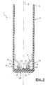
- the tube 1 shown in Figures 1A and 2 in its configuration before filling comprises a tubular body 2, one end 3 of which is open.
- the body tubular 2 is formed by extruding a polypropylene.
- a head 4 produced by injection, especially polypropylene.
- the head forms a neck 5 whose outer surface has a snap bead 6 and a free edge of which defines an opening 7 for the tube.
- a capsule 8 On the head 4 of the tube 1, is mounted by snap-fastening a capsule 8 comprising a body 9 fixedly mounted on the head 4 of the tube.
- the body 9 includes a first skirt 10 whose internal surface has a groove 11 able to cooperate with the bead 6 so as to ensure the fixing of the capsule on the tube.
- the body 9 of the capsule also includes a second skirt 12 intended to seal inside the neck of the tube.
- a transverse wall 14 of the body 9 of the capsule has in its center a orifice 15 for dispensing the product.
- a "cap” 16 On the body 9 of the capsule is articulated a "cap" 16 whose surface internal comprises a lug 17 which, in the closed position as shown in the cross-section of FIG. 2, seals the dispensing orifice 15 in a leaktight manner.
- the outer surface of the cap 16 is substantially flat so that the tube 1 can rest stably on the latter.
- FIGS. 1A-1C illustrate the steps filling the tube according to a particular embodiment of the invention.
- the tube 1 is turned upside down. In this position, the capsule 8 is in the closed position, and the cap 16 rests stably on a flat surface. The end 3 of the tube is open.
- a first product is introduced into the tube via the open end 3 of the latter, up to a level of filling located substantially at two thirds of the axial height of the tube.
- a transverse weld zone 20 is performed, in particular with ultrasound, and this, just above the level of filling in Figure 1A.
- a pre-cutting line is produced in dotted lines 21, extending over the entire width of the tube 1. This is done a first compartment 22, a first end of which is closed by a zone solder 20 and a second end of which is equipped with the capsule 8.
- the next step is, using a cane filling 51, to be introduced into the part of the tube 1 located above the closing zone 20, via the open end 3, a sample product, of preference different from the first product, until the level of substantially maximum filling of tube 1 is reached.
- FIG. 1C the end 3 of the tube has been closed along a weld zone 23.
- a second compartment is thus delimited between the closing zones 20 and 23 24, completely isolated from the first.
- a notch or primer of tear 25 intended to favor the opening of compartment 24.
- the compartment 24 is separated from the compartment 22, along the precut line 21.
- the compartment 24 is open at the level of the tear initiator 25.
- the sample product contained in compartment 24 is distributed via the opening 26 resulting from the rupture of the tear initiator 25.
- compartment 22 the contents of compartment 22 are distributed identically to the how the product in a conventional tube is dispensed.
- the cap 16 is opened, and the product leaves via the orifice 15 of the capsule 8 in response to pressure exerted on the deformable walls of the tube.
- the closing zone 20 comprises a straight edge 27 on the side of the compartment 22 and a non-straight edge 28 on the side of the compartment 24.
- the non-straight edge 28 is such that the compartment 24 forms a protrusion 29 substantially in the axis of the tube 1, and turned towards the compartment 22.
- the narrowest end of the projection 29 is at a non-zero distance from a line pre-cutting 21 along which the two compartments 22 and 24 are intended to be separated.
- the outgrowth 29 extends on either side of a line transverse of lesser thickness 30 according to which the weld zone 20 is at cut or tear manually to allow the opening of the compartment 24.
- the filling of the tube 1 according to this embodiment is identical to that of the previous embodiment, except for the weld zone end 23 which, unlike the previous embodiment, does not include no tear initiation.
- FIGS 5A-5D to which reference is now made illustrate a possible sequence of use of the tube discussed with reference to Figures 4A-4C.
- the compartment 24 is separated from the compartment 22, along the precut line 21.
- the compartment 24 is opened by making a cut along the line of weakness 30, which intercepts the non-straight edge 28 at two points of the closing area 20.
- An opening 26 is formed and extends between the two so-called edge points 28.
- the sample product contained in compartment 24 is dispensed via opening 26.
- the content of compartment 22 is distributed identically to the how the product in a conventional tube is dispensed.
- the cap 16 is opened, and the product leaves via the orifice 15 of the capsule 8 in response to pressure exerted on the deformable walls of the tube.
Abstract
Description
La présente invention a trait à un tube pour le conditionnement d'un produit et d'un échantillon associé au produit. L'invention est tout particulièrement adaptée au conditionnement de produits cosmétiques, en particulier de produits capillaires, notamment de coiffage, de nettoyage, de soin, ou de coloration, ou des produits d'hygiène corporelle, de soin de la peau, ou de protection contre les rayonnements néfastes du soleil.The present invention relates to a tube for packaging a product and a sample associated with the product. The invention is particularly suitable for packaging of cosmetic products, in particular hair products, including styling, cleaning, care, or coloring, or products personal hygiene, skin care, or radiation protection harmful from the sun.
On connaít du document US-A-2002/0029985, un tube comportant deux chambres pour conditionner deux produits séparément et pouvoir ensuite mélanger ces produits en mettant en communication les deux chambres.We know from document US-A-2002/0029985, a tube comprising two rooms to package two products separately and then be able to mix these products by connecting the two chambers.
Dans le domaine cosmétique en particulier, la distribution d'échantillons, associée à la vente d'un ou plusieurs produits, est fréquente. Elle permet en particulier de faire découvrir à la consommatrice (ou au consommateur) d'autres produits que celui ou ceux qu'elle (ou qu'il) achète, en vue bien entendu d'un futur achat du produit échantillonné.In the cosmetic field in particular, the distribution of samples, associated when selling one or more products, is frequent. It allows in particular to introduce the consumer to other products than the one or those she (or he) buys, with a view of course to a future purchase of the sampled product.
Un des problèmes liés au conditionnement sous forme d'échantillons tient :
Concernant le dernier point, l'échantillon peut être donné par la caissière, au moment du paiement du produit acheté. Ce mode de présentation ne se prête pas bien à la grande distribution, dans laquelle, il serait souhaitable que le produit acheté soit présenté directement avec le produit échantillon, et ce, sans modifier de manière sensible, le coût ou la présentation du produit acheté.Regarding the last point, the sample can be given by the cashier, at time of payment for the product purchased. This mode of presentation is not suitable good to mass retail, in which, it would be desirable that the product purchased is presented directly with the sample product, without modifying significantly, the cost or presentation of the product purchased.
Se pose alors le problème des tubes, lesquels peuvent être présentés sans autre forme de conditionnement extérieur. Une solution consisterait bien entendu à coller, ou fixer par tout autre moyen, l'échantillon sur le tube. Outre l'esthétique, cette solution est préjudiciable du point de vue du coût dans la mesure où elle rajoute une opération de conditionnement qu'il est par ailleurs difficile d'automatiser. En outre, le risque est grand pour que, notamment lors du transport, l'échantillon se sépare du produit auquel il est associé.The problem then arises of the tubes, which can be presented without further form of external packaging. One solution would of course be to stick, or fix by any other means, the sample on the tube. Besides the aesthetics, this solution is detrimental from the point of view of cost insofar as it add a packaging operation that is otherwise difficult automate. In addition, there is a great risk that, in particular when transport, the sample separates from the product with which it is associated.
Aussi, est-ce un des objets de l'invention que de réaliser un tube pour le conditionnement d'un produit et d'un échantillon associé au produit, et qui résolve en tout ou partie, les problèmes discutés ci-avant.It is therefore one of the objects of the invention to produce a tube for the packaging of a product and a sample associated with the product, and which resolves in whole or in part, the problems discussed above.
C'est en particulier un objet de l'invention que de réaliser un tel conditionnement qui soit économique à réaliser, et dont la présentation de l'échantillon relativement au produit auquel il est associé, soit améliorée relativement aux présentations conventionnelles.It is in particular an object of the invention to produce such packaging which is economical to carry out, and whose presentation of the sample relatively to the product to which it is associated, be improved with respect to presentations conventional.
D'autres objets encore apparaítront dans la description détaillée qui suit.Other objects will appear in the detailed description which follows.
Selon l'invention, ces objets sont atteints en réalisant un tube souple d'axe X, dont
une première extrémité délimite un orifice de sortie, une seconde extrémité
opposée à la première étant fermée selon une zone de fermeture d'extrémité
obtenue par la fixation sur lui même, notamment par soudage ou collage, d'un
bord d'extrémité dudit tube, le tube comprenant en outre au moins une zone de
fermeture intermédiaire formée entre les première et seconde extrémités, à
distance non nulle de ces dernières, et obtenue par la fixation sur elle même,
selon au moins une ligne transversale audit axe X, d'une paroi dudit tube, de
manière à définir au moins deux compartiments isolés l'un de l'autre:
Ainsi, avec le même corps de tube, sont délimités deux compartiments, l'un contenant un produit, l'autre contenant un échantillon d'un produit identique ou différent du produit contenu dans le premier compartiment. De ce fait, aucune opération de fixation de l'un à l'autre n'est requise. Le risque de voir l'échantillon, en particulier lors du transport, se désolidariser du produit est réduit de manière substantielle par rapport au même risque associé aux systèmes conventionnels discutés précédemment.Thus, with the same tube body, two compartments are delimited, one containing one product, the other containing a sample of an identical product or different from the product in the first compartment. Therefore, no fixing operation from one to the other is not required. The risk of seeing the sample, particularly during transport, separation from the product is reduced so substantial compared to the same risk associated with conventional systems previously discussed.
La zone de fermeture intermédiaire comprend des moyens, notamment sous forme d'une ligne de faiblesse ou d'une prédécoupe, pour faciliter la séparation des deux compartiments.The intermediate closure zone comprises means, in particular under form of a line of weakness or a precut, to facilitate separation of the two compartments.
Avantageusement, les moyens pour faciliter la séparation se rompent sous l'effet d'une traction manuelle exercée sur chacun des deux compartiments. La traction est par exemple exercée en tenant dans une main l'un des compartiments, et dans l'autre main l'autre compartiment, la séparation étant obtenue par un geste d'écartement des mains l'une de l'autre.Advantageously, the means for facilitating the separation break under the effect manual traction exerted on each of the two compartments. Traction is for example exercised by holding one of the compartments in one hand, and in the other hand the other compartment, the separation being obtained by a gesture hands apart from each other.
La zone de fermeture intermédiaire est de préférence rectiligne, et sensiblement perpendiculaire à l'axe du tube. Toutefois, ceci ne constitue pas une obligation, ladite zone pouvant être en particulier courbe, inclinée relativement à l'axe, ou s'étendre selon un zigzag.The intermediate closure zone is preferably rectilinear, and substantially perpendicular to the axis of the tube. However, this is not an obligation, said zone possibly being in particular curved, inclined relative to the axis, or extend in a zigzag.
Avantageusement, l'une au moins desdites zones de fermeture présente un bord non rectiligne de manière à permettre, lors de l'ouverture du second compartiment, de délimiter un passage de sortie localisé pour le produit contenu dans le second compartiment.Advantageously, at least one of said closure zones has an edge not straight so as to allow, when the second compartment is opened, to delimit a localized exit passage for the product contained in the second compartment.
Ainsi, en découpant la zone de fermeture présentant ledit bord non rectiligne, selon une découpe rectiligne, interceptant de préférence en au moins deux points ledit bord non rectiligne, une ouverture est formée entre les deux dits points.Thus, by cutting out the closure zone having said non-straight edge, according to a straight cut, preferably intercepting at least two points said non-straight edge, an opening is formed between the two said points.
De préférence, ledit bord non rectiligne est formé par la zone de fermeture intermédiaire et délimite une excroissance en communication avec le second compartiment, et tournée en direction du premier. Ainsi, par une découpe telle que décrite précédemment, un passage de faible largeur, de préférence centré sur l'axe longitudinal du tube, est défini de manière à permettre la distribution localisée du produit. Preferably, said non-straight edge is formed by the closure zone intermediate and defines a protuberance in communication with the second compartment, and turned towards the first. So, by a cut such as described above, a passage of small width, preferably centered on the longitudinal axis of the tube, is defined so as to allow localized distribution of the product.
Des moyens, notamment sous forme d'une amorce de découpe ou de déchirure ou d'une ligne de faiblesse ou de prédécoupe sont prévus pour favoriser l'ouverture manuelle du second compartiment. De tels moyens peuvent être prévus soit au niveau de la zone de fermeture d'extrémité, soit au niveau de la zone de fermeture intermédiaire. A nouveau, faute de tels moyens pré-existants, l'ouverture peut se faire par une simple découpe au moyen d'une paire de ciseaux.Means, in particular in the form of a cutting or tearing primer or a line of weakness or precut are provided to favor manual opening of the second compartment. Such means can be provided either at the end closure area or at the intermediate closing area. Again, in the absence of such pre-existing means, the opening can be done by a simple cut using a pair of scissors.
De préférence, le tube comprend un corps tubulaire obtenu par extrusion d'une couche d'au moins un matériau thermoplastique, notamment un polyéthylène, haute ou basse densité, ou un polypropylène, ou par laminage ou coextrusion d'un complexe à plusieurs couches comprenant au moins un matériau thermoplastique.Preferably, the tube comprises a tubular body obtained by extruding a layer of at least one thermoplastic material, in particular a polyethylene, high or low density, or polypropylene, or by rolling or coextruding a multi-layer complex comprising at least one thermoplastic material.
La surface extérieure du corps, à l'exception éventuellement des portions de surface correspondant aux deux zones de fermeture, peut comporter un vernis, destiné notamment à en favoriser le décor.The outer surface of the body, with the possible exception of portions of surface corresponding to the two closing zones, may include a varnish, intended in particular to favor the decoration.
L'orifice de sortie du tube peut être délimité par une tête rapportée sur le corps du tube, et, montée sur ce dernier, notamment par soudage ou collage. La tête est obtenue de préférence par injection.The outlet opening of the tube can be delimited by a head attached to the body of the tube, and mounted on the latter, in particular by welding or gluing. The head is preferably obtained by injection.
La zone de fermeture d'extrémité et la zone de fermeture intermédiaire peuvent être obtenues par collage ou soudure, notamment à chaud ou aux ultra-sons.The end closing area and the intermediate closing area can be obtained by bonding or welding, in particular hot or ultrasonic.
Avantageusement, la première extrémité du tube est équipée d'une capsule de distribution comprenant un orifice pour la distribution du produit, en communication, au moins sélective, avec ledit orifice de sortie, et un élément de fermeture pour obturer de manière réversible ledit orifice de distribution.Advantageously, the first end of the tube is equipped with a capsule of distribution comprising an orifice for the distribution of the product, in communication, at least selective, with said outlet, and an element of closure for reversibly closing said dispensing orifice.
De manière plus spécifique, la capsule de distribution peut comprendre un corps monté fixement sur le tube, notamment par claquage ou par vissage, et délimitant ledit orifice de distribution, ledit élément de fermeture étant articulé sur ledit corps, notamment via une charnière film ou une charnière à effet ressort. L'élément de fermeture peut être également vissé ou encliqueté sur le corps de la capsule. More specifically, the dispensing capsule may include a body fixedly mounted on the tube, in particular by snap-fastening or by screwing, and delimiting said dispensing orifice, said closing element being articulated on said body, in particular via a film hinge or a spring effect hinge. The element of closure can also be screwed or snapped onto the body of the capsule.
Selon un autre aspect de l'invention, on réalise également un procédé de
conditionnement à l'intérieur d'un tube souple d'axe X, d'un produit et d'un produit
échantillon associé audit produit, ledit procédé consistant à :
Alternativement, dans le cas où le produit conditionné dans les deux
compartiments est le même, il est possible de procéder selon la séquence
suivante :
Une configuration selon laquelle le produit et le produit échantillon sont identiques trouve application notamment pour un usage "nomade" du second compartiment. Ainsi, pour les besoins d'un week-end par exemple, la consommatrice peut, dans un souci de limiter le volume de sa trousse de toilette, ne prendre avec elle que l'échantillon.A configuration according to which the product and the sample product are identical finds application especially for "nomadic" use of the second compartment. Thus, for the purposes of a weekend for example, the consumer can, in a concern to limit the volume of her toilet bag, take with her only the sample.
Le produit et le produit échantillon peuvent être des produits à usage cosmétique, notamment des produits de coiffage, d'hygiène corporelle ou du cheveu, de soin de la peau ou du cheveu, ou des produits de protection contre les effets néfastes du rayonnement solaire.The product and the sample product can be products for cosmetic use, in particular styling, personal or hair hygiene, care products of the skin or hair, or of products for protection against harmful effects of solar radiation.
L'invention consiste, mises à part les dispositions exposées ci-dessus, en un certain nombre d'autres dispositions qui seront explicitées ci-après, à propos d'exemples de réalisation non limitatifs, décrits en référence aux figures annexées, parmi lesquelles :
- les figures 1A-1C illustrent le conditionnement d'un produit et d'un échantillon associé au produit, dans un tube selon un premier mode de réalisation de l'invention ;
- la figure 2 est une vue en coupe du tube dans sa configuration de la figure 1A ;
- les figures 3A-3D illustrent l'utilisation du tube représenté aux figures 1A-
1C et 2; - les figures 4A-4C illustrent le conditionnement d'un produit et d'un échantillon associé au produit, dans un tube selon un second mode de réalisation de l'invention ; et
- les figures 5A-5D illustrent l'utilisation du tube illustré aux figures 4A-4C.
- FIGS. 1A-1C illustrate the packaging of a product and of a sample associated with the product, in a tube according to a first embodiment of the invention;
- Figure 2 is a sectional view of the tube in its configuration of Figure 1A;
- Figures 3A-3D illustrate the use of the tube shown in Figures 1A-1C and 2;
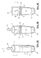
- FIGS. 4A-4C illustrate the packaging of a product and of a sample associated with the product, in a tube according to a second embodiment of the invention; and
- Figures 5A-5D illustrate the use of the tube illustrated in Figures 4A-4C.
Le tube 1 représenté aux figures 1A et 2, dans sa configuration avant remplissage
comprend un corps tubulaire 2 dont une extrémité 3 est ouverte. Le corps
tubulaire 2 est formé par extrusion d'un polypropylène.The
Sur l'autre extrémité, est fixée par soudage, une tête 4, réalisée par injection,
notamment en polypropylène. La tête forme un col 5 dont la surface extérieure
comporte un bourrelet de claquage 6 et dont un bord libre délimite une ouverture 7
pour le tube.On the other end, is fixed by welding, a
Sur la tête 4 du tube 1, est montée par encliquetage une capsule 8 comportant un
corps 9 monté fixement sur la tête 4 de tube. A cet effet, le corps 9 comporte une
première jupe 10 dont la surface interne comporte une gorge 11 apte à coopérer
avec le bourrelet 6 de manière à assurer la fixation de la capsule sur le tube.On the
Le corps 9 de la capsule comprend également une seconde jupe 12 destinée à
faire étanchéité à l'intérieur du col du tube.The body 9 of the capsule also includes a
Il comprend en outre une troisième jupe 13, ayant principalement une fonction
d'habillage.It further comprises a
Une paroi transversale 14 du corps 9 de la capsule comporte en son centre un
orifice 15 pour la distribution du produit.A
Sur le corps 9 de la capsule est articulée une "casquette" 16 dont la surface
interne comporte un ergot 17 qui, en position fermée telle que représentée sur la
vue en coupe de la figure 2, obture de manière étanche l'orifice de distribution 15.On the body 9 of the capsule is articulated a "cap" 16 whose surface
internal comprises a
La surface externe de la casquette 16 est sensiblement plane de sorte que le tube
1 puisse reposer de façon stable sur cette dernière.The outer surface of the
Les figures 1A-1C auxquelles il est maintenant fait référence, illustrent les étapes de remplissage du tube selon un mode de réalisation particulier de l'invention. Figures 1A-1C to which reference is now made, illustrate the steps filling the tube according to a particular embodiment of the invention.
Sur la figure 1A, le tube 1 est retourné tête en bas. Dans cette position, la capsule
8 est en position fermée, et la casquette 16 repose de façon stable sur une
surface plane. L'extrémité 3 du tube est ouverte.In FIG. 1A, the
Au moyen d'une canne de remplissage 50, un premier produit est introduit dans le
tube via l'extrémité ouverte 3 de ce dernier, et ce jusqu'à un niveau de
remplissage situé sensiblement aux deux tiers de la hauteur axiale du tube.By means of a filling
Après l'étape de remplissage de la figure 1A, une zone de soudure transversale
20 est effectuée, notamment aux ultra-sons, et ce, juste au dessus du niveau de
remplissage de la figure 1A.After the filling step of FIG. 1A, a
Sensiblement au milieu de cette zone de soudure 20, on réalise une ligne de pré-découpe
en pointillés 21, s'étendant sur toute la largeur du tube 1. On réalise ainsi
un premier compartiment 22 dont une première extrémité est fermée par une zone
de soudure 20 et dont une seconde extrémité est équipée de la capsule 8.Significantly in the middle of this
Comme il apparaít à la figure 1B, l'étape suivante consiste, au moyen d'une canne
de remplissage 51, à introduire dans la partie du tube 1 située au dessus de la
zone de fermeture 20, via l'extrémité ouverte 3, un produit échantillon, de
préférence différent du premier produit, et ce jusqu'à ce que le niveau de
remplissage sensiblement maximal du tube 1 soit atteint.As it appears in Figure 1B, the next step is, using a cane
filling 51, to be introduced into the part of the
A la figure 1C, l'extrémité 3 du tube a été fermée selon une zone de soudure 23.
On délimite ainsi entre les zones de fermeture 20 et 23, un second compartiment
24, totalement isolé du premier.In FIG. 1C, the
On réalise ensuite dans la zone de fermeture 23 une encoche ou amorce de
déchirure 25 destinée à favoriser l'ouverture du compartiment 24.Next, in the
Les figures 3A-3D auxquelles il est maintenant fait référence, illustrent une séquence possible d'utilisation du tube discuté en référence aux figures 1A-1C et 2. Figures 3A-3D to which reference is now made illustrate a possible sequence of use of the tube discussed with reference to FIGS. 1A-1C and 2.
A la figure 3A, le compartiment 24 est séparé du compartiment 22, le long de la
ligne de prédécoupe 21.In FIG. 3A, the
A la figure 3B, le compartiment 24 est ouvert au niveau de l'amorce de déchirure
25.In FIG. 3B, the
A la figure 3C, le produit échantillon contenu dans le compartiment 24 est distribué
via l'ouverture 26 résultant de la rupture de l'amorce de déchirure 25.In FIG. 3C, the sample product contained in
A la figure 3D, le contenu du compartiment 22 est distribué de façon identique à la
façon dont le produit contenu dans un tube conventionnel est distribué.
Typiquement, la casquette 16 est ouverte, et le produit sort via l'orifice 15 de la
capsule 8 en réponse à une pression exercée sur les parois déformables du tube.In FIG. 3D, the contents of
Le mode de réalisation du tube 1 dont une séquence de remplissage est illustrée
aux figures 4A-4C se distingue du mode de réalisation précédent, essentiellement
dans la conception de la zone de fermeture intermédiaire 20 séparant les
compartiments 22 et 24.The embodiment of
Selon ce mode de réalisation, la zone de fermeture 20 comprend un bord droit 27
du côté du compartiment 22 et un bord non rectiligne 28 du côté du compartiment
24.According to this embodiment, the
Le bord non rectiligne 28 est tel que le compartiment 24 forme une excroissance
29 sensiblement dans l'axe du tube 1, et tournée en direction du compartiment 22.The
L'extrémité la plus étroite de l'excroissance 29 est à distance non nulle d'une ligne
de pré-découpe 21 le long de laquelle les deux compartiments 22 et 24 sont
destinés à être séparés. L'excroissance 29 s'étend de part et d'autre d'une ligne
transversale de moindre épaisseur 30 selon laquelle la zone de soudure 20 est à
découper ou déchirer manuellement en vue de permettre l'ouverture du
compartiment 24. The narrowest end of the
Pour le reste, le remplissage du tube 1 selon ce mode de réalisation est identique
à celui du mode de réalisation précédent, exception faite de la zone de soudure
d'extrémité 23 qui, contrairement au mode de réalisation précédent, ne comporte
pas d'amorce de déchirure.For the rest, the filling of the
Les figures 5A-5D auxquelles il est maintenant fait référence, illustrent une séquence possible d'utilisation du tube discuté en référence aux figures 4A-4C.Figures 5A-5D to which reference is now made illustrate a possible sequence of use of the tube discussed with reference to Figures 4A-4C.
A la figure 5A, le compartiment 24 est séparé du compartiment 22, le long de la
ligne de prédécoupe 21.In FIG. 5A, the
A la figure 5B, le compartiment 24 est ouvert en réalisant une découpe le long de
la ligne de faiblesse 30, laquelle intercepte en deux points le bord non rectiligne 28
de la zone de fermeture 20. Une ouverture 26 est formée et s'étend entre les deux
dits points du bord 28.In FIG. 5B, the
A la figure 5C, le produit échantillon contenu dans le compartiment 24 est distribué
via l'ouverture 26.In FIG. 5C, the sample product contained in
A la figure 5D, le contenu du compartiment 22 est distribué de façon identique à la
façon dont le produit contenu dans un tube conventionnel est distribué.
Typiquement, la casquette 16 est ouverte, et le produit sort via l'orifice 15 de la
capsule 8 en réponse à une pression exercée sur les parois déformables du tube.In FIG. 5D, the content of
Dans la description détaillée qui précède, il a été fait référence à des modes de réalisation préférés de l'invention. Il est évident que des variantes peuvent y être apportées sans s'écarter de l'esprit de l'invention telle que revendiquée ci-après.In the foregoing detailed description, reference has been made to modes of preferred embodiments of the invention. Obviously there may be variations made without departing from the spirit of the invention as claimed below.
Claims (13)
Applications Claiming Priority (2)
| Application Number | Priority Date | Filing Date | Title |
|---|---|---|---|
| FR0205002A FR2838713B1 (en) | 2002-04-22 | 2002-04-22 | TUBE FOR PACKAGING A PRODUCT AND A SAMPLE ASSOCIATED WITH THE PRODUCT |
| FR0205002 | 2002-04-22 |
Publications (2)
| Publication Number | Publication Date |
|---|---|
| EP1357047A1 true EP1357047A1 (en) | 2003-10-29 |
| EP1357047B1 EP1357047B1 (en) | 2006-01-18 |
Family
ID=28686244
Family Applications (1)
| Application Number | Title | Priority Date | Filing Date |
|---|---|---|---|
| EP03290779A Expired - Lifetime EP1357047B1 (en) | 2002-04-22 | 2003-03-27 | Tube for the packaging of a product with associated sample |
Country Status (5)
| Country | Link |
|---|---|
| EP (1) | EP1357047B1 (en) |
| AT (1) | ATE316045T1 (en) |
| DE (1) | DE60303270T2 (en) |
| ES (1) | ES2257648T3 (en) |
| FR (1) | FR2838713B1 (en) |
Cited By (2)
| Publication number | Priority date | Publication date | Assignee | Title |
|---|---|---|---|---|
| FR2885357A1 (en) * | 2005-05-03 | 2006-11-10 | Oreal | Flexible tube for packing cosmetic product, has line of weakness extending across end closing zone or intermediate closing zone and across portion of wall delimiting compartment which forms sample sachet |
| WO2013042063A1 (en) | 2011-09-21 | 2013-03-28 | L'oreal | Sachet with at least two compartments |
Families Citing this family (2)
| Publication number | Priority date | Publication date | Assignee | Title |
|---|---|---|---|---|
| FR3077275B1 (en) * | 2018-01-29 | 2020-01-24 | Lydia Schiffmann | TUBE FOR PACKAGING A FLUID PRODUCT |
| WO2020249876A1 (en) | 2019-06-14 | 2020-12-17 | Lydia Schiffmann | Tube for packaging a fluid product, kit comprising such a tube, use and process for such a tube |
Citations (5)
| Publication number | Priority date | Publication date | Assignee | Title |
|---|---|---|---|---|
| US29985A (en) | 1860-09-11 | Improvement in harvesting-machines | ||
| GB1081586A (en) * | 1964-09-08 | 1967-08-31 | Spiess C F & Sohn | Plastics dispensing container |
| DE2111701A1 (en) * | 1971-03-11 | 1972-09-14 | Spiess C F & Sohn | Packing bag |
| CH585647A5 (en) * | 1973-10-19 | 1977-03-15 | Sebamat Chemie Gmbh | Assembly of tubular metal or plastic containers - has two tubes joined at their ends or along adjacent sides |
| US20020029985A1 (en) * | 2000-06-26 | 2002-03-14 | Linda Stunnell | Storing and mixing container and method for separately depositing, storing and mixing two substances in a container |
-
2002
- 2002-04-22 FR FR0205002A patent/FR2838713B1/en not_active Expired - Lifetime
-
2003
- 2003-03-27 AT AT03290779T patent/ATE316045T1/en not_active IP Right Cessation
- 2003-03-27 ES ES03290779T patent/ES2257648T3/en not_active Expired - Lifetime
- 2003-03-27 DE DE60303270T patent/DE60303270T2/en not_active Expired - Lifetime
- 2003-03-27 EP EP03290779A patent/EP1357047B1/en not_active Expired - Lifetime
Patent Citations (5)
| Publication number | Priority date | Publication date | Assignee | Title |
|---|---|---|---|---|
| US29985A (en) | 1860-09-11 | Improvement in harvesting-machines | ||
| GB1081586A (en) * | 1964-09-08 | 1967-08-31 | Spiess C F & Sohn | Plastics dispensing container |
| DE2111701A1 (en) * | 1971-03-11 | 1972-09-14 | Spiess C F & Sohn | Packing bag |
| CH585647A5 (en) * | 1973-10-19 | 1977-03-15 | Sebamat Chemie Gmbh | Assembly of tubular metal or plastic containers - has two tubes joined at their ends or along adjacent sides |
| US20020029985A1 (en) * | 2000-06-26 | 2002-03-14 | Linda Stunnell | Storing and mixing container and method for separately depositing, storing and mixing two substances in a container |
Cited By (2)
| Publication number | Priority date | Publication date | Assignee | Title |
|---|---|---|---|---|
| FR2885357A1 (en) * | 2005-05-03 | 2006-11-10 | Oreal | Flexible tube for packing cosmetic product, has line of weakness extending across end closing zone or intermediate closing zone and across portion of wall delimiting compartment which forms sample sachet |
| WO2013042063A1 (en) | 2011-09-21 | 2013-03-28 | L'oreal | Sachet with at least two compartments |
Also Published As
| Publication number | Publication date |
|---|---|
| DE60303270D1 (en) | 2006-04-06 |
| EP1357047B1 (en) | 2006-01-18 |
| ES2257648T3 (en) | 2006-08-01 |
| FR2838713B1 (en) | 2004-12-24 |
| FR2838713A1 (en) | 2003-10-24 |
| ATE316045T1 (en) | 2006-02-15 |
| DE60303270T2 (en) | 2006-09-21 |
Similar Documents
| Publication | Publication Date | Title |
|---|---|---|
| EP1270444B1 (en) | Device for simultaneously distributing two separately packaged products | |
| FR2733206A1 (en) | FLEXIBLE CONDITIONING TUBE | |
| EP1300344A1 (en) | Device for storing separately and co-dispensing two products | |
| CA2356711A1 (en) | Device for separate packaging and joint discharge of two products to be mixed extemporaneously | |
| EP1165246B1 (en) | Pouch and packaging and distribution unit | |
| FR2784968A1 (en) | METERING CAP AND CONTAINER PROVIDED WITH A METERING CAP according to the invention | |
| EP3027081A1 (en) | Dispensing and application head | |
| FR2767797A1 (en) | DEVICE FOR THE EXTEMPORANEOUS MIXING OF AT LEAST TWO PRODUCTS | |
| EP0803210A1 (en) | Packaging pouch for a cream or paste like product; manufacturing process therefor and a make-up case containing such a product | |
| FR2999062A1 (en) | PACKAGING FOR A PULVERIZABLE COSMETIC FLUID CONSISTING OF A FLEXIBLE POCKET AND A PERIPHERAL FRAME | |
| FR2794433A1 (en) | FLAT BAG, SEALED | |
| EP1114775A1 (en) | Flat container for samples | |
| EP1357047B1 (en) | Tube for the packaging of a product with associated sample | |
| EP1072527B1 (en) | Package for viscous products with increased rate of emptying | |
| CA3059377A1 (en) | Multilayer plastic tube structure | |
| WO2001098162A1 (en) | Flexible tube provided with large diameter neck and rigid end cap | |
| EP1232798B1 (en) | Spray device for samples | |
| FR2879418A1 (en) | Cosmetic product e.g. mascara, applicator-distributor, has pouch with partition unit to form upper and lower cavities, where lower cavity has breaking unit to break film that forms envelope of cavity, to grasp and utilize gripping unit | |
| EP1678052B1 (en) | Fluid product dispensing assembly | |
| FR3077275A1 (en) | TUBE FOR PACKAGING A FLUID PRODUCT | |
| FR2526756A1 (en) | PROCESS FOR SEALING PACKAGES MADE OF A LAMINATE COMPLEX | |
| FR2753438A1 (en) | Container for holding two ingredients that are mixed prior to use | |
| FR2845674A3 (en) | Single dose container for liquid condiments made from adhesion of two plastic sheets has pre-cut opening tabs, product opening being composed of two lips with edges in contact to retain liquid by capillary action | |
| FR2885357A1 (en) | Flexible tube for packing cosmetic product, has line of weakness extending across end closing zone or intermediate closing zone and across portion of wall delimiting compartment which forms sample sachet | |
| WO2020249876A1 (en) | Tube for packaging a fluid product, kit comprising such a tube, use and process for such a tube |
Legal Events
| Date | Code | Title | Description |
|---|---|---|---|
| PUAI | Public reference made under article 153(3) epc to a published international application that has entered the european phase |
Free format text: ORIGINAL CODE: 0009012 |
|
| AK | Designated contracting states |
Kind code of ref document: A1 Designated state(s): AT BE BG CH CY CZ DE DK EE ES FI FR GB GR HU IE IT LI LU MC NL PT RO SE SI SK TR |
|
| AX | Request for extension of the european patent |
Extension state: AL LT LV MK |
|
| 17P | Request for examination filed |
Effective date: 20040429 |
|
| AKX | Designation fees paid |
Designated state(s): AT BE BG CH CY CZ DE DK EE ES FI FR GB GR HU IE IT LI LU MC NL PT RO SE SI SK TR |
|
| GRAP | Despatch of communication of intention to grant a patent |
Free format text: ORIGINAL CODE: EPIDOSNIGR1 |
|
| GRAJ | Information related to disapproval of communication of intention to grant by the applicant or resumption of examination proceedings by the epo deleted |
Free format text: ORIGINAL CODE: EPIDOSDIGR1 |
|
| GRAP | Despatch of communication of intention to grant a patent |
Free format text: ORIGINAL CODE: EPIDOSNIGR1 |
|
| GRAS | Grant fee paid |
Free format text: ORIGINAL CODE: EPIDOSNIGR3 |
|
| GRAA | (expected) grant |
Free format text: ORIGINAL CODE: 0009210 |
|
| AK | Designated contracting states |
Kind code of ref document: B1 Designated state(s): AT BE BG CH CY CZ DE DK EE ES FI FR GB GR HU IE IT LI LU MC NL PT RO SE SI SK TR |
|
| PG25 | Lapsed in a contracting state [announced via postgrant information from national office to epo] |
Ref country code: SK Free format text: LAPSE BECAUSE OF FAILURE TO SUBMIT A TRANSLATION OF THE DESCRIPTION OR TO PAY THE FEE WITHIN THE PRESCRIBED TIME-LIMIT Effective date: 20060118 Ref country code: AT Free format text: LAPSE BECAUSE OF FAILURE TO SUBMIT A TRANSLATION OF THE DESCRIPTION OR TO PAY THE FEE WITHIN THE PRESCRIBED TIME-LIMIT Effective date: 20060118 Ref country code: SI Free format text: LAPSE BECAUSE OF FAILURE TO SUBMIT A TRANSLATION OF THE DESCRIPTION OR TO PAY THE FEE WITHIN THE PRESCRIBED TIME-LIMIT Effective date: 20060118 Ref country code: NL Free format text: LAPSE BECAUSE OF FAILURE TO SUBMIT A TRANSLATION OF THE DESCRIPTION OR TO PAY THE FEE WITHIN THE PRESCRIBED TIME-LIMIT Effective date: 20060118 Ref country code: RO Free format text: LAPSE BECAUSE OF FAILURE TO SUBMIT A TRANSLATION OF THE DESCRIPTION OR TO PAY THE FEE WITHIN THE PRESCRIBED TIME-LIMIT Effective date: 20060118 Ref country code: IE Free format text: LAPSE BECAUSE OF FAILURE TO SUBMIT A TRANSLATION OF THE DESCRIPTION OR TO PAY THE FEE WITHIN THE PRESCRIBED TIME-LIMIT Effective date: 20060118 Ref country code: FI Free format text: LAPSE BECAUSE OF FAILURE TO SUBMIT A TRANSLATION OF THE DESCRIPTION OR TO PAY THE FEE WITHIN THE PRESCRIBED TIME-LIMIT Effective date: 20060118 |
|
| REG | Reference to a national code |
Ref country code: GB Ref legal event code: FG4D Free format text: NOT ENGLISH |
|
| REG | Reference to a national code |
Ref country code: CH Ref legal event code: EP |
|
| REG | Reference to a national code |
Ref country code: IE Ref legal event code: FG4D Free format text: LANGUAGE OF EP DOCUMENT: FRENCH |
|
| PG25 | Lapsed in a contracting state [announced via postgrant information from national office to epo] |
Ref country code: MC Free format text: LAPSE BECAUSE OF NON-PAYMENT OF DUE FEES Effective date: 20060331 Ref country code: LU Free format text: LAPSE BECAUSE OF NON-PAYMENT OF DUE FEES Effective date: 20060331 Ref country code: BE Free format text: LAPSE BECAUSE OF NON-PAYMENT OF DUE FEES Effective date: 20060331 |
|
| REF | Corresponds to: |
Ref document number: 60303270 Country of ref document: DE Date of ref document: 20060406 Kind code of ref document: P |
|
| PG25 | Lapsed in a contracting state [announced via postgrant information from national office to epo] |
Ref country code: SE Free format text: LAPSE BECAUSE OF FAILURE TO SUBMIT A TRANSLATION OF THE DESCRIPTION OR TO PAY THE FEE WITHIN THE PRESCRIBED TIME-LIMIT Effective date: 20060418 Ref country code: BG Free format text: LAPSE BECAUSE OF FAILURE TO SUBMIT A TRANSLATION OF THE DESCRIPTION OR TO PAY THE FEE WITHIN THE PRESCRIBED TIME-LIMIT Effective date: 20060418 Ref country code: DK Free format text: LAPSE BECAUSE OF FAILURE TO SUBMIT A TRANSLATION OF THE DESCRIPTION OR TO PAY THE FEE WITHIN THE PRESCRIBED TIME-LIMIT Effective date: 20060418 |
|
| GBT | Gb: translation of ep patent filed (gb section 77(6)(a)/1977) |
Effective date: 20060329 |
|
| PG25 | Lapsed in a contracting state [announced via postgrant information from national office to epo] |
Ref country code: PT Free format text: LAPSE BECAUSE OF FAILURE TO SUBMIT A TRANSLATION OF THE DESCRIPTION OR TO PAY THE FEE WITHIN THE PRESCRIBED TIME-LIMIT Effective date: 20060619 |
|
| NLV1 | Nl: lapsed or annulled due to failure to fulfill the requirements of art. 29p and 29m of the patents act | ||
| REG | Reference to a national code |
Ref country code: ES Ref legal event code: FG2A Ref document number: 2257648 Country of ref document: ES Kind code of ref document: T3 |
|
| REG | Reference to a national code |
Ref country code: IE Ref legal event code: FD4D |
|
| PLBE | No opposition filed within time limit |
Free format text: ORIGINAL CODE: 0009261 |
|
| STAA | Information on the status of an ep patent application or granted ep patent |
Free format text: STATUS: NO OPPOSITION FILED WITHIN TIME LIMIT |
|
| 26N | No opposition filed |
Effective date: 20061019 |
|
| REG | Reference to a national code |
Ref country code: CH Ref legal event code: PL |
|
| BERE | Be: lapsed |
Owner name: L'OREAL Effective date: 20060331 |
|
| PG25 | Lapsed in a contracting state [announced via postgrant information from national office to epo] |
Ref country code: CH Free format text: LAPSE BECAUSE OF NON-PAYMENT OF DUE FEES Effective date: 20070331 Ref country code: LI Free format text: LAPSE BECAUSE OF NON-PAYMENT OF DUE FEES Effective date: 20070331 |
|
| PG25 | Lapsed in a contracting state [announced via postgrant information from national office to epo] |
Ref country code: CZ Free format text: LAPSE BECAUSE OF FAILURE TO SUBMIT A TRANSLATION OF THE DESCRIPTION OR TO PAY THE FEE WITHIN THE PRESCRIBED TIME-LIMIT Effective date: 20060118 Ref country code: GR Free format text: LAPSE BECAUSE OF FAILURE TO SUBMIT A TRANSLATION OF THE DESCRIPTION OR TO PAY THE FEE WITHIN THE PRESCRIBED TIME-LIMIT Effective date: 20060419 |
|
| PG25 | Lapsed in a contracting state [announced via postgrant information from national office to epo] |
Ref country code: EE Free format text: LAPSE BECAUSE OF FAILURE TO SUBMIT A TRANSLATION OF THE DESCRIPTION OR TO PAY THE FEE WITHIN THE PRESCRIBED TIME-LIMIT Effective date: 20060118 |
|
| PG25 | Lapsed in a contracting state [announced via postgrant information from national office to epo] |
Ref country code: HU Free format text: LAPSE BECAUSE OF FAILURE TO SUBMIT A TRANSLATION OF THE DESCRIPTION OR TO PAY THE FEE WITHIN THE PRESCRIBED TIME-LIMIT Effective date: 20060719 Ref country code: TR Free format text: LAPSE BECAUSE OF FAILURE TO SUBMIT A TRANSLATION OF THE DESCRIPTION OR TO PAY THE FEE WITHIN THE PRESCRIBED TIME-LIMIT Effective date: 20060118 |
|
| PG25 | Lapsed in a contracting state [announced via postgrant information from national office to epo] |
Ref country code: CY Free format text: LAPSE BECAUSE OF FAILURE TO SUBMIT A TRANSLATION OF THE DESCRIPTION OR TO PAY THE FEE WITHIN THE PRESCRIBED TIME-LIMIT Effective date: 20060118 |
|
| PGFP | Annual fee paid to national office [announced via postgrant information from national office to epo] |
Ref country code: IT Payment date: 20120321 Year of fee payment: 10 |
|
| PGFP | Annual fee paid to national office [announced via postgrant information from national office to epo] |
Ref country code: ES Payment date: 20130313 Year of fee payment: 11 Ref country code: GB Payment date: 20130327 Year of fee payment: 11 Ref country code: FR Payment date: 20130325 Year of fee payment: 11 Ref country code: DE Payment date: 20130320 Year of fee payment: 11 |
|
| REG | Reference to a national code |
Ref country code: DE Ref legal event code: R119 Ref document number: 60303270 Country of ref document: DE |
|
| GBPC | Gb: european patent ceased through non-payment of renewal fee |
Effective date: 20140327 |
|
| REG | Reference to a national code |
Ref country code: FR Ref legal event code: ST Effective date: 20141128 |
|
| REG | Reference to a national code |
Ref country code: DE Ref legal event code: R119 Ref document number: 60303270 Country of ref document: DE Effective date: 20141001 |
|
| PG25 | Lapsed in a contracting state [announced via postgrant information from national office to epo] |
Ref country code: FR Free format text: LAPSE BECAUSE OF NON-PAYMENT OF DUE FEES Effective date: 20140331 Ref country code: GB Free format text: LAPSE BECAUSE OF NON-PAYMENT OF DUE FEES Effective date: 20140327 Ref country code: DE Free format text: LAPSE BECAUSE OF NON-PAYMENT OF DUE FEES Effective date: 20141001 |
|
| PG25 | Lapsed in a contracting state [announced via postgrant information from national office to epo] |
Ref country code: IT Free format text: LAPSE BECAUSE OF NON-PAYMENT OF DUE FEES Effective date: 20140327 |
|
| REG | Reference to a national code |
Ref country code: ES Ref legal event code: FD2A Effective date: 20150731 |
|
| PG25 | Lapsed in a contracting state [announced via postgrant information from national office to epo] |
Ref country code: ES Free format text: LAPSE BECAUSE OF NON-PAYMENT OF DUE FEES Effective date: 20140328 |