EP1357017A1 - Rahmenstruktur eines Fahrzeugs - Google Patents
Rahmenstruktur eines Fahrzeugs Download PDFInfo
- Publication number
- EP1357017A1 EP1357017A1 EP03007481A EP03007481A EP1357017A1 EP 1357017 A1 EP1357017 A1 EP 1357017A1 EP 03007481 A EP03007481 A EP 03007481A EP 03007481 A EP03007481 A EP 03007481A EP 1357017 A1 EP1357017 A1 EP 1357017A1
- Authority
- EP
- European Patent Office
- Prior art keywords
- frame part
- sheet metal
- metal component
- tubular
- structure according
- Prior art date
- Legal status (The legal status is an assumption and is not a legal conclusion. Google has not performed a legal analysis and makes no representation as to the accuracy of the status listed.)
- Granted
Links
Images


Classifications
-
- B—PERFORMING OPERATIONS; TRANSPORTING
- B62—LAND VEHICLES FOR TRAVELLING OTHERWISE THAN ON RAILS
- B62D—MOTOR VEHICLES; TRAILERS
- B62D29/00—Superstructures, understructures, or sub-units thereof, characterised by the material thereof
- B62D29/007—Superstructures, understructures, or sub-units thereof, characterised by the material thereof predominantly of special steel or specially treated steel, e.g. stainless steel or locally surface hardened steel
-
- B—PERFORMING OPERATIONS; TRANSPORTING
- B62—LAND VEHICLES FOR TRAVELLING OTHERWISE THAN ON RAILS
- B62D—MOTOR VEHICLES; TRAILERS
- B62D23/00—Combined superstructure and frame, i.e. monocoque constructions
- B62D23/005—Combined superstructure and frame, i.e. monocoque constructions with integrated chassis in the whole shell, e.g. meshwork, tubes, or the like
-
- B—PERFORMING OPERATIONS; TRANSPORTING
- B62—LAND VEHICLES FOR TRAVELLING OTHERWISE THAN ON RAILS
- B62D—MOTOR VEHICLES; TRAILERS
- B62D25/00—Superstructure or monocoque structure sub-units; Parts or details thereof not otherwise provided for
- B62D25/02—Side panels
-
- B—PERFORMING OPERATIONS; TRANSPORTING
- B62—LAND VEHICLES FOR TRAVELLING OTHERWISE THAN ON RAILS
- B62D—MOTOR VEHICLES; TRAILERS
- B62D25/00—Superstructure or monocoque structure sub-units; Parts or details thereof not otherwise provided for
- B62D25/04—Door pillars ; windshield pillars
-
- B—PERFORMING OPERATIONS; TRANSPORTING
- B62—LAND VEHICLES FOR TRAVELLING OTHERWISE THAN ON RAILS
- B62D—MOTOR VEHICLES; TRAILERS
- B62D27/00—Connections between superstructure or understructure sub-units
- B62D27/02—Connections between superstructure or understructure sub-units rigid
- B62D27/023—Assembly of structural joints
-
- B—PERFORMING OPERATIONS; TRANSPORTING
- B62—LAND VEHICLES FOR TRAVELLING OTHERWISE THAN ON RAILS
- B62D—MOTOR VEHICLES; TRAILERS
- B62D27/00—Connections between superstructure or understructure sub-units
- B62D27/02—Connections between superstructure or understructure sub-units rigid
- B62D27/026—Connections by glue bonding
Definitions
- the invention relates to a frame structure of a Vehicle, in particular a motor vehicle, with a Node structure between a first, tubular frame part and a second frame part after that in the preamble of claim 1 specified type.
- Vehicle frames like that of a motor vehicle, are usually carried out in lattice frame construction, whereby the lattice through differently shaped cast, extrusion and aluminum sheet profiles, which is formed by Nodes are connected.
- nodes In vehicle bodies known from practice, which is carried out with a so-called space frame structure these nodes are usually separated by Node elements formed, at least two of them together frame parts to be connected with their end faces be firmly connected.
- Such separate node elements are in different Manufacturing processes manufactured, such. B. as cast node elements, as described in EP 0 671 312 A1 are described, or as extruded light metal profiles according to DE 44 07 501 A1 or as mechanized prefabricated fiber preforms with a three-dimensional continuous fiber structure and pockets for the associated frame profile parts, such as it is described in DE 44 23 642 C1.
- node elements made of steel with precise connections produced by a hydroforming process
- the node elements described therein, which are for connection are provided on pre-profiled pipe profiles, are closed deformed components made of sheet steel, which with the help of a liquid applied High pressure are deformed so that they at least a connecting piece for a pre-profiled Form the frame part.
- node elements are related to their Manufacturing the node elements described above are superior, so when used in a Frame structure of a vehicle disadvantageous that such a connection of a frame part to a highly stressed carrier element the latter by the Node connection broken and thus significantly weakened becomes. Because of the large number of required Connection areas, has such a structure Frame structure numerous vulnerabilities, apart from from the considerable manufacturing effort required to manufacture such a frame structure is required.
- US 6,241,310 B1 describes a vehicle frame, having a first tubular frame part with a node area that is angled from a Longitudinal axis of the tubular frame part extends away and by so-called hydroforming, i.e. a hydroforming through liquid.
- This node area represents a connecting piece, on the second, a corresponding, opening Frame part attached and firmly connected to this becomes.
- Frame structure of a vehicle especially one Motor vehicle to create a knot structure between a first tubular frame part and a second frame part with the smallest possible number of components is realized, and one of which is too expected loads adequately adapted and yet easily executed frame structure is achieved.
- a frame structure designed according to the invention of a vehicle in which at least one connecting piece to connect at least a second frame part a first frame part an internal high pressure forming element represents which consists of a circumferential applied to the first tubular frame part Sheet metal component is formed has the advantage that first frame part not weakened by a separation with which it is significantly higher loads than a to form the connection piece or a node structure frame part interrupted with a node element can record.
- first frame part not weakened by a separation with which it is significantly higher loads than a to form the connection piece or a node structure frame part interrupted with a node element can record.
- the connection piece provided sheet metal component reinforcement of the frame structure in the area of the node structure achieved.
- inventive design Frame structure advantageous with that in such a way realized knot structure the wall thickness of the first, tubular frame part not affected becomes.
- the frame structure according to Invention a coordination of the required individual Wall thickness of a basic element first, tubular frame part and the at least a connection piece possible. Doing the voting the wall thickness on the one hand with regard to weight optimization the frame structure of the vehicle and on the other hand with regard to the loads to be expected on the individual frame parts.
- the frame structure is distinctive according to the invention by the small number of needed Components and their simple, inexpensive Producibility from, the connecting piece for connection suitable for frame parts of any profile are.
- Both the first tubular frame part as well the second frame part to be connected can with regard their cross-sectional shape, any, for example in Oval, circular, rectangular or in other shapes, be trained.
- the sheet metal component the first, tubular frame part only on its circumference encloses areas.
- the production of the node structure using a Hydroforming in the first, tube-like Frame part an internal high pressure preferably through a fluid is introduced that has a suitable Transfer the peripheral opening to the sheet metal component is and is set so that the material of the Sheet metal component against a form of the connecting piece Specifying wall of a hydroforming tool is pressed, can advantageously also for Form a firm connection with the second one the connecting piece to be used frame part become. If the second frame part to be connected with a corresponding opening for receiving the connecting piece in the hydroforming tool the formation of the connecting piece from the sheet metal component is arranged, the sheet metal component in one Work in said opening of the second frame part be pressed in.
- FIG. 1 schematically shows part of a frame structure 1 of a convertible motor vehicle Motor vehicle 2 shown, three exemplarily Node structures 3, 4, 5 are shown, of which a first node structure 3 between an A pillar 7 of the convertible motor vehicle in the area of a bend arranged to a windshield frame 6 is and a connection between a first, tubular, the A-pillar-forming frame part 7 and one second frame part delimiting a hood frame 8 forms.
- a second node structure 4 forms one Connection between the frame part forming the A-pillar 7 and a tubular one with a hollow profile Vehicle side members or side skirts 9, while the third node structure 5 shown is a connection between the vehicle side member 9 and one B-pillar 10 arranged at the rear of a vehicle door of the vehicle.
- FIG. 2 to 5 is an enlarged view Representation according to an area shown in FIG. 1 X the tubular frame part 7 representing the A-pillar and a circumferential side on the tubular frame part 7 applied sheet metal component 12 to form a connecting piece 11 in different production stages shown in more detail.
- FIG. 2 shows the tubular frame part 7 and that encasing this, partially depicted in the outbreak Sheet metal component 12 as a semi-finished product for the formation of Connection piece 11 before a hydroforming of the sheet metal component 12 by means of hydroforming.
- This one likewise a sheet metal component 12 representing a piece of pipe is in the area of the connecting piece to be trained 11 positioned and at its ends with the tubular Frame part 7 via welded connections 13, 14 watertight connected.
- other types of connection such as B. adhesive connections provided his.
- the curved shape of this component grouping will by bending the first tubular frame part 7 together with the sheet metal component 12 before training the Connection piece 11 generated.
- liquid pressure on the sheet metal component 12 are in the present Execution in the area of the connecting piece to be trained two peripheral openings 15 and 16 are provided, which through holes represent.
- the openings 15, 16 can of course be used in other versions also on another one for each Use case suitable way in the tubular Frame part 7 are introduced.
- the pre-bent or prepared semi-finished product is now in an internal high-pressure forming tool 17, which in 2 and 3 is indicated by dashed lines, inserted, the first tubular frame part 7 in the area of the connecting piece 11 to be trained as well the sheet metal component 12 applied thereon in the edge region thereof from the hydroforming tool 17 directly is enclosed.
- the area of the trainee Connector 11 is in the hydroforming tool 17 as a cavity with a contour of Connection piece defining wall 18 is formed.
- FIG. 4 and FIG. 5 is the connecting piece 11 shown after the hydroforming, the outer contour the connecting piece 11 for the connection of the further Frame part 8 is suitably formed.
- This Connection is here as one shown in Fig. 1 in more detail Plug connection carried out at the connecting piece 11 into a cavity 19 of the frame part 8 to to a bend 20 on the outer contour of the connecting piece 11 is inserted so that the outer contour the node structure 3 is essentially smooth. In the node structure 3 described here, this is Frame part 8 on the connecting piece 11 via not closer shown welds attached.
- each is a reference the node structure 4 more specifically designated sheet metal component 12 ⁇ applied to the tubular vehicle side member 9, each with a connector 11 ⁇ in the top described manner from the sheet metal component 12 ⁇ Hydroforming is trained.
- the one to be connected to this in the node structure 4 A-pillar frame part 7 is with a press connection the connecting piece 11 'connected, the press connection here during the hydroforming of the connector 11 ⁇ is produced.
- a connecting piece to be connected frame part in the Insert high-pressure forming tool so that the connecting piece against an inside of the to be connected Frame part during the forming process trains and a clamp connection with the to be connected Manufactures frame part.
- node structures 3, 4 shown in FIG. 1, 5 is the connecting piece 11, 11 'in one Cavity 19 or 21 used, but it is in others Remarks of course also possible that the frame part to be connected in one at the connecting piece shaped recess is used.
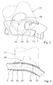
- connection piece from a applied to a tubular frame part, itself a sheet metal component representing a pipe can be made according to a 6 and FIG. 7 embodiment variant shown in more detail also be provided that a connecting piece 11 '' by hydroforming from a sheet metal component 12 '' is formed, which has a tubular frame part 22 whose scope only encompasses areas.
- the sheet metal component 12 '' also in the embodiment shown here by means of a continuous, waterproof Weld 23 attached to the tubular frame part 22.
- the tubular frame part 22 in turn has two Through bores 24, 25 on which the passage of liquid pressure medium to the sheet metal component 12 '' during a hydroforming process to develop the Allow 11 '' connector.
- the choice of the design of the node structure which in other versions, for example with two Connection piece can be designed depends on the expected maximum loads on the concerned Frame parts. While, for example, in the area the node structure 3 is one shown in FIGS. 1 to 5 Design of the to form the connecting piece serving sheet metal component in tube form as well comparatively high wall thicknesses are preferable because there is a bending area of the A-pillar to a windshield frame in convertible vehicles a safety-critical one Area which is the rollover protection function the windshield frame in the event of an accident of the vehicle must be designed accordingly, can be used for node structures where a lower maximum load is estimated, even a thinner one Wall and a sheet metal component to form a Connection piece according to that shown in Fig. 5 and Fig. 6 Find application.
- the specialist becomes dependent on the expected load also the suitable materials and the type of Choose fasteners, such as one Welded joint, mechanical fasteners such as Screws or rivets, or chemical fasteners like glue. With especially it remains heavily used node structures Leave to a specialist, if necessary also foaming the existing cavities with rigid foam to increase stiffness.
- connection piece as well as the shape of the frame parts in cross section and at least partly in Longitudinal direction produced by hydroforming.
- the entire frame structure of a Motor vehicle is manufactured by means of hydroforming, wherein also an additional shape of the frame parts outside of the connector area by, if necessary other known manufacturing techniques can be done.
Landscapes
- Engineering & Computer Science (AREA)
- Chemical & Material Sciences (AREA)
- Combustion & Propulsion (AREA)
- Transportation (AREA)
- Mechanical Engineering (AREA)
- Architecture (AREA)
- Structural Engineering (AREA)
- Body Structure For Vehicles (AREA)
- Motor Or Generator Frames (AREA)
Abstract
Description
- Fig. 1
- einen Teil einer Rahmenstruktur einer Fahrzeugkarosserie in einer Seitenansicht;
- Fig. 2
- ein rohrartiges Rahmenteil im Bereich einer Knotenstruktur gemäß einem Ausschnitt X in Fig. 1 mit einem das rohrartige Rahmenteil umschließenden Blechbauteil, wobei ein Zustand vor Ausbildung eines Anschlußstutzens aus dem Blechbauteil durch eine Innenhochdruck-Umformung dargestellt ist;
- Fig. 3
- einen Längsschnitt durch das rohrartige Rahmenteil und das dieses umgebende Blechbauteil gemäß Fig. 2;
- Fig. 4
- das Rahmenteil mit dem Blechbauteil nach Fig. 2 und Fig. 3, wobei hier ein Zustand nach Ausbildung des Anschlußstutzens aus dem Blechbauteil dargestellt ist;
- Fig. 5
- eine Darstellung des rohrartigen Rahmenteils und des einen Anschlußstutzen bildenden Blechbauteils gemäß Fig. 4 im Längsschnitt;
- Fig. 6
- eine weitere Ausführung einer Knotenstruktur mit einem rohrförmigen Rahmenteil, welches umfangsseitig bereichsweise ein Blechbauteil umschließt, wobei ein Zustand vor Ausbildung eines Anschlußstutzens aus dem Blechbauteil durch Innenhochdruck-Umformung dargestellt ist;
- Fig. 7
- das Rahmenteil und das Blechbauteil nach Fig. 6, wobei hier ein Zustand nach Ausbildung des Anschlußstutzens aus dem Blechbauteil dargestellt ist.
Claims (14)
- Rahmenstruktur eines Fahrzeugs, insbesondere eines Kraftwagens, mit einer Knotenstruktur zwischen einem ersten, rohrartigen Rahmenteil und einem zweiten Rahmenteil, wobei wenigstens ein Anschlußstutzen zur Anbindung wenigstens des zweiten Rahmenteils an dem ersten Rahmenteil als ein Innenhochdruck-Umformelement ausgebildet ist,
dadurch gekennzeichnet, daß der wenigstens eine Anschlußstutzen (11; 11'; 11") aus einem umfangsseitig auf das erste, rohrartige Rahmenteil (7; 9; 22) aufgebrachten Blechbauteil (12; 12'; 12' ') ausgebildet ist. - Rahmenstruktur nach Anspruch 1,
dadurch gekennzeichnet, daß das Blechbauteil (12; 12`; 12' ' ) mit dem ersten, rohrartigen Rahmenteil (7; 9; 22) randseitig fest verbunden ist. - Rahmenstruktur nach Anspruch 2,
dadurch gekennzeichnet, daß die Verbindung zwischen dem Blechbauteil (12; 12`; 12' ') und dem ersten, rohrartigen Rahmenteil (7; 9; 22) dichtend ist. - Rahmenstruktur nach Anspruch 2 oder 3,
dadurch gekennzeichnet, daß das Blechbauteil (12; 12`; 12``) mit dem ersten, rohrartigen Rahmenteil (7; 9; 22) mittels einer Schweißverbindung (13, 14; 23) verbunden ist. - Rahmenstruktur nach einem der Ansprüche 1 bis 4,
dadurch gekennzeichnet, daß das Blechbauteil (12; 12`) als ein Rohr ausgebildet ist, welches das erste, rohrartige Rahmenteil (7; 9) wenigstens im Bereich der Knotenstruktur (3; 4) vollständig umschließt. - Rahmenstruktur nach einem der Ansprüche 1 bis 4,
dadurch gekennzeichnet, daß das Blechbauteil (12' ') das erste, rohrartige Rahmenteil (22) auf dessen Umfang nur bereichsweise umschließt. - Rahmenstruktur nach einem der Ansprüche 1 bis 6,
dadurch gekennzeichnet, daß das erste, rohrartige Rahmenteil (7; 9; 22) im Bereich des den Anschlußstutzen (11; 11'; 11' ') bildenden Blechbauteiles (12; 12`; 12``) mit wenigstens einer umfangsseitigen Öffnung (15, 16; 24, 25) ausgebildet ist, mittels derer das Blechbauteil (12; 12`; 12``) zur Ausbildung des Anschlußstutzens (11; 11'; 11' ') mit einem in das rohrartige Rahmenteil (7; 9; 22) eingebrachten Innenhochdruck beaufschlagbar ist. - Rahmenstruktur nach Anspruch 7,
dadurch gekennzeichnet, daß die wenigstens eine umfangsseitige Öffnung als Durchgangsbohrung (15, 16; 24, 25) ausgebildet ist. - Rahmenstruktur nach einem der Ansprüche 1 bis 8,
dadurch gekennzeichnet, daß das erste, rohrartige Rahmenteil (7; 9; 22) zusammen mit dem aufgebrachten Blechbauteil (12; 12`; 12``) vor der Innenhochdruck-Umformung vorgebogen ist. - Rahmenstruktur nach einem der Ansprüche 1 bis 9,
dadurch gekennzeichnet, daß wenigstens der Anschlußstutzen (11; 11`; 11' ') ein Hydroforming-Element darstellt. - Rahmenstruktur nach einem der Ansprüche 1 bis 10,
dadurch gekennzeichnet, daß wenigstens das erste, rohrartige Rahmenteil (7; 9; 22) als ein Trägerelement ausgebildet ist. - Rahmenstruktur nach einem der Ansprüche 1 bis 11,
dadurch gekennzeichnet, daß das erste, rohrartige Rahmenteil ein Fahrzeuglängsträger (9) und das zweiten Rahmenteil eine Fahrzeugsäule (7, 10) darstellen. - Rahmenstruktur nach einem der Ansprüche 1 bis 12,
dadurch gekennzeichnet, daß das erste, rohrartige Rahmenteil eine A-Säule (7) eines Cabriolet-Fahrzeugs darstellt, wobei die Knotenstruktur (3) in einem Knickbereich zur Ausbildung eines Windschutzscheibenrahmens (6) angeordnet ist. - Rahmenstruktur nach einem der Ansprüche 1 bis 13,
dadurch gekennzeichnet, daß die Anbindung des zweiten Rahmenteils an den Anschlußstutzen (11`) als eine während der Innenhochdruckumformung des Anschlußstutzens (11`) hergestellte Klemmverbindung ausgeführt ist.
Applications Claiming Priority (2)
| Application Number | Priority Date | Filing Date | Title |
|---|---|---|---|
| DE20206524U | 2002-04-25 | ||
| DE20206524U DE20206524U1 (de) | 2002-04-25 | 2002-04-25 | Rahmenstruktur eines Fahrzeugs |
Publications (2)
| Publication Number | Publication Date |
|---|---|
| EP1357017A1 true EP1357017A1 (de) | 2003-10-29 |
| EP1357017B1 EP1357017B1 (de) | 2011-06-22 |
Family
ID=7970497
Family Applications (1)
| Application Number | Title | Priority Date | Filing Date |
|---|---|---|---|
| EP03007481A Expired - Lifetime EP1357017B1 (de) | 2002-04-25 | 2003-04-07 | Rahmenstruktur eines Fahrzeugs |
Country Status (3)
| Country | Link |
|---|---|
| EP (1) | EP1357017B1 (de) |
| AT (1) | ATE513723T1 (de) |
| DE (1) | DE20206524U1 (de) |
Cited By (2)
| Publication number | Priority date | Publication date | Assignee | Title |
|---|---|---|---|---|
| CN108657275A (zh) * | 2018-07-05 | 2018-10-16 | 广东纵行科技有限公司 | 一种车架装置 |
| US20230031824A1 (en) * | 2021-07-30 | 2023-02-02 | Caterpillar Inc. | Connector for interconnecting frame members of a space frame assembly |
Families Citing this family (3)
| Publication number | Priority date | Publication date | Assignee | Title |
|---|---|---|---|---|
| DE20302615U1 (de) | 2003-02-17 | 2004-07-15 | Tower Automotive Gmbh & Co. Kg | Hohlformteil mit geschlossenem Querschnitt und einer Verstärkung |
| DE102009015157A1 (de) * | 2009-03-26 | 2010-09-30 | Volkswagen Ag | Verbindungsanordnung zur Verbindung eines Säulenfußes einer Karosseriesäule eines Kraftfahrzeugs mit einem Längsträger |
| DE102010010592A1 (de) * | 2010-03-08 | 2011-07-07 | Audi Ag, 85057 | Fahrzeugkarosserieaufbau im Bereich unterhalb eines hinteren Seitenfensters |
Citations (7)
| Publication number | Priority date | Publication date | Assignee | Title |
|---|---|---|---|---|
| US4355844A (en) * | 1979-05-25 | 1982-10-26 | Fiat Auto S.P.A. | Skeletal load-bearing structures for motor vehicles |
| EP0671312A1 (de) | 1994-03-09 | 1995-09-13 | Automobiles Peugeot | Kraftwagenstruktur mit mindestens einer Knotenpunktverbindung für langgestreckte Elemente, wie Rahmenlangsträger, Pfosten, Querträger des Wagens |
| DE4423642C1 (de) | 1994-07-06 | 1995-10-12 | Daimler Benz Aerospace Ag | Tragrahmen, insbesondere für ein Kraftfahrzeug |
| US5720092A (en) * | 1996-08-21 | 1998-02-24 | General Motors Corporation | Method for hydroforming a vehicle space frame |
| DE19653509A1 (de) | 1996-12-20 | 1998-06-25 | Volkswagen Ag | Rahmenstruktur einer Fahrzeugkarosserie aus Knotenelementen und angeschlossenen, vorprofilierten Trägerelementen |
| US6241310B1 (en) | 2000-05-17 | 2001-06-05 | Asc Incorporated | Vehicle structure with integral node |
| WO2001081155A2 (en) * | 2000-04-21 | 2001-11-01 | Haba Chaz | Coupling member for interconnecting profiles to create a frame assembly |
-
2002
- 2002-04-25 DE DE20206524U patent/DE20206524U1/de not_active Expired - Lifetime
-
2003
- 2003-04-07 AT AT03007481T patent/ATE513723T1/de active
- 2003-04-07 EP EP03007481A patent/EP1357017B1/de not_active Expired - Lifetime
Patent Citations (7)
| Publication number | Priority date | Publication date | Assignee | Title |
|---|---|---|---|---|
| US4355844A (en) * | 1979-05-25 | 1982-10-26 | Fiat Auto S.P.A. | Skeletal load-bearing structures for motor vehicles |
| EP0671312A1 (de) | 1994-03-09 | 1995-09-13 | Automobiles Peugeot | Kraftwagenstruktur mit mindestens einer Knotenpunktverbindung für langgestreckte Elemente, wie Rahmenlangsträger, Pfosten, Querträger des Wagens |
| DE4423642C1 (de) | 1994-07-06 | 1995-10-12 | Daimler Benz Aerospace Ag | Tragrahmen, insbesondere für ein Kraftfahrzeug |
| US5720092A (en) * | 1996-08-21 | 1998-02-24 | General Motors Corporation | Method for hydroforming a vehicle space frame |
| DE19653509A1 (de) | 1996-12-20 | 1998-06-25 | Volkswagen Ag | Rahmenstruktur einer Fahrzeugkarosserie aus Knotenelementen und angeschlossenen, vorprofilierten Trägerelementen |
| WO2001081155A2 (en) * | 2000-04-21 | 2001-11-01 | Haba Chaz | Coupling member for interconnecting profiles to create a frame assembly |
| US6241310B1 (en) | 2000-05-17 | 2001-06-05 | Asc Incorporated | Vehicle structure with integral node |
Cited By (4)
| Publication number | Priority date | Publication date | Assignee | Title |
|---|---|---|---|---|
| CN108657275A (zh) * | 2018-07-05 | 2018-10-16 | 广东纵行科技有限公司 | 一种车架装置 |
| CN108657275B (zh) * | 2018-07-05 | 2019-08-02 | 广东纵行科技有限公司 | 一种车架装置 |
| US20230031824A1 (en) * | 2021-07-30 | 2023-02-02 | Caterpillar Inc. | Connector for interconnecting frame members of a space frame assembly |
| US11884329B2 (en) * | 2021-07-30 | 2024-01-30 | Caterpillar Inc. | Connector for interconnecting frame members of a space frame assembly |
Also Published As
| Publication number | Publication date |
|---|---|
| ATE513723T1 (de) | 2011-07-15 |
| DE20206524U1 (de) | 2002-08-29 |
| EP1357017B1 (de) | 2011-06-22 |
Similar Documents
| Publication | Publication Date | Title |
|---|---|---|
| DE19653509B4 (de) | Rahmenstruktur einer Fahrzeugkarosserie aus Knotenelementen und angeschlossenen, vorprofilierten Trägerelementen | |
| EP2301826B1 (de) | Knotenelement für eine Fahrzeugrahmenstruktur | |
| EP2994367B1 (de) | Säule für eine kraftfahrzeug-rohbaustruktur, verfahren zur herstellung einer säule und kraftfahrzeug-rohbaustruktur | |
| DE102007018459B4 (de) | Karosseriebauteil für einen Kraftwagen | |
| DE10022360A1 (de) | Profilverbundbauteil und Verfahren zu seiner Herstellung | |
| EP1621453A2 (de) | Fahrzeugkarosserie mit Einzelteilen aus variabler Blechdicke | |
| DE19506160A1 (de) | Rahmenkonstruktion für Kraftfahrzeuge | |
| DE102011120180A1 (de) | Karosseriebauteil | |
| DE10042618A1 (de) | Karosserie- und Rahmenanordnung | |
| DE102008056507A1 (de) | Fahrzeugaufbau für ein Kraftfahrzeug | |
| DE102005045781B4 (de) | Rahmenstruktur | |
| DE102009015157A1 (de) | Verbindungsanordnung zur Verbindung eines Säulenfußes einer Karosseriesäule eines Kraftfahrzeugs mit einem Längsträger | |
| DE102005011834B4 (de) | Seitlicher Dachrahmen für ein Kraftfahrzeug | |
| WO2004050459A1 (de) | Seitenwandmodul für ein kraftfahrzeug und herstellungsverfahren für eine kraftfahrzeugkarosserie | |
| DE102013222016A1 (de) | Verfahren zum Herstellen eines verstärkten Faserverbundbauteils in Schalenbauweise | |
| EP2332810A2 (de) | Karosserie eines Kraftfahrzeugs | |
| DE102009058976A1 (de) | Schwellerbaugruppe für eine Fahrzeugkarosserie sowie Verfahren zur Herstellung einer Schwellerbaugruppe | |
| EP1357017B1 (de) | Rahmenstruktur eines Fahrzeugs | |
| DE19946013B4 (de) | Seitengerippe für eine selbsttragende Karosserie eines Kraftfahrzeuges | |
| DE102012020182A1 (de) | Strukturelement für eine Kraftfahrzeug-Rohbaustruktur | |
| EP3266685B1 (de) | Karosseriestruktur für ein nutzfahrzeug | |
| DE102005051440B4 (de) | Seitenwandbaugruppe für eine Kraftfahrzeugkarosserie eines insbesondere Personenkraftfahrzeuges | |
| DE102015204917A1 (de) | Seitentür für ein Fahrzeug sowie Fahrzeug mit einer derartigen Seitentür | |
| DE4335029C2 (de) | A-Säulenverbindungsteil und Verfahren zu seiner Herstellung | |
| DE102016013301A1 (de) | Fahrzeugsäule für ein Kraftfahrzeug und Verfahren zum Herstellen einer Fahrzeugsäule für ein Kraftfahrzeug |
Legal Events
| Date | Code | Title | Description |
|---|---|---|---|
| PUAI | Public reference made under article 153(3) epc to a published international application that has entered the european phase |
Free format text: ORIGINAL CODE: 0009012 |
|
| AK | Designated contracting states |
Kind code of ref document: A1 Designated state(s): AT BE BG CH CY CZ DE DK EE ES FI FR GB GR HU IE IT LI LU MC NL PT RO SE SI SK TR |
|
| AX | Request for extension of the european patent |
Extension state: AL LT LV MK |
|
| AKX | Designation fees paid | ||
| 17P | Request for examination filed |
Effective date: 20040612 |
|
| RBV | Designated contracting states (corrected) |
Designated state(s): AT BE BG CH CY CZ DE DK EE ES FI FR GB GR HU IE IT LI LU MC NL PT RO SE SI SK TR |
|
| REG | Reference to a national code |
Ref country code: DE Ref legal event code: 8566 |
|
| GRAP | Despatch of communication of intention to grant a patent |
Free format text: ORIGINAL CODE: EPIDOSNIGR1 |
|
| 19U | Interruption of proceedings before grant |
Effective date: 20090629 |
|
| 19W | Proceedings resumed before grant after interruption of proceedings |
Effective date: 20101201 |
|
| GRAC | Information related to communication of intention to grant a patent modified |
Free format text: ORIGINAL CODE: EPIDOSCIGR1 |
|
| GRAS | Grant fee paid |
Free format text: ORIGINAL CODE: EPIDOSNIGR3 |
|
| GRAA | (expected) grant |
Free format text: ORIGINAL CODE: 0009210 |
|
| AK | Designated contracting states |
Kind code of ref document: B1 Designated state(s): AT BE BG CH CY CZ DE DK EE ES FI FR GB GR HU IE IT LI LU MC NL PT RO SE SI SK TR |
|
| REG | Reference to a national code |
Ref country code: GB Ref legal event code: FG4D Free format text: NOT ENGLISH |
|
| REG | Reference to a national code |
Ref country code: CH Ref legal event code: EP |
|
| REG | Reference to a national code |
Ref country code: IE Ref legal event code: FG4D Free format text: LANGUAGE OF EP DOCUMENT: GERMAN |
|
| REG | Reference to a national code |
Ref country code: DE Ref legal event code: R096 Ref document number: 50313773 Country of ref document: DE Effective date: 20110804 |
|
| REG | Reference to a national code |
Ref country code: NL Ref legal event code: VDEP Effective date: 20110622 |
|
| PG25 | Lapsed in a contracting state [announced via postgrant information from national office to epo] |
Ref country code: SE Free format text: LAPSE BECAUSE OF FAILURE TO SUBMIT A TRANSLATION OF THE DESCRIPTION OR TO PAY THE FEE WITHIN THE PRESCRIBED TIME-LIMIT Effective date: 20110622 |
|
| PG25 | Lapsed in a contracting state [announced via postgrant information from national office to epo] |
Ref country code: FI Free format text: LAPSE BECAUSE OF FAILURE TO SUBMIT A TRANSLATION OF THE DESCRIPTION OR TO PAY THE FEE WITHIN THE PRESCRIBED TIME-LIMIT Effective date: 20110622 Ref country code: CY Free format text: LAPSE BECAUSE OF FAILURE TO SUBMIT A TRANSLATION OF THE DESCRIPTION OR TO PAY THE FEE WITHIN THE PRESCRIBED TIME-LIMIT Effective date: 20110622 Ref country code: SI Free format text: LAPSE BECAUSE OF FAILURE TO SUBMIT A TRANSLATION OF THE DESCRIPTION OR TO PAY THE FEE WITHIN THE PRESCRIBED TIME-LIMIT Effective date: 20110622 Ref country code: GR Free format text: LAPSE BECAUSE OF FAILURE TO SUBMIT A TRANSLATION OF THE DESCRIPTION OR TO PAY THE FEE WITHIN THE PRESCRIBED TIME-LIMIT Effective date: 20110923 |
|
| PG25 | Lapsed in a contracting state [announced via postgrant information from national office to epo] |
Ref country code: NL Free format text: LAPSE BECAUSE OF FAILURE TO SUBMIT A TRANSLATION OF THE DESCRIPTION OR TO PAY THE FEE WITHIN THE PRESCRIBED TIME-LIMIT Effective date: 20110622 |
|
| REG | Reference to a national code |
Ref country code: IE Ref legal event code: FD4D |
|
| PG25 | Lapsed in a contracting state [announced via postgrant information from national office to epo] |
Ref country code: IE Free format text: LAPSE BECAUSE OF FAILURE TO SUBMIT A TRANSLATION OF THE DESCRIPTION OR TO PAY THE FEE WITHIN THE PRESCRIBED TIME-LIMIT Effective date: 20110622 Ref country code: CZ Free format text: LAPSE BECAUSE OF FAILURE TO SUBMIT A TRANSLATION OF THE DESCRIPTION OR TO PAY THE FEE WITHIN THE PRESCRIBED TIME-LIMIT Effective date: 20110622 Ref country code: EE Free format text: LAPSE BECAUSE OF FAILURE TO SUBMIT A TRANSLATION OF THE DESCRIPTION OR TO PAY THE FEE WITHIN THE PRESCRIBED TIME-LIMIT Effective date: 20110622 Ref country code: PT Free format text: LAPSE BECAUSE OF FAILURE TO SUBMIT A TRANSLATION OF THE DESCRIPTION OR TO PAY THE FEE WITHIN THE PRESCRIBED TIME-LIMIT Effective date: 20111024 |
|
| PG25 | Lapsed in a contracting state [announced via postgrant information from national office to epo] |
Ref country code: RO Free format text: LAPSE BECAUSE OF FAILURE TO SUBMIT A TRANSLATION OF THE DESCRIPTION OR TO PAY THE FEE WITHIN THE PRESCRIBED TIME-LIMIT Effective date: 20110622 Ref country code: SK Free format text: LAPSE BECAUSE OF FAILURE TO SUBMIT A TRANSLATION OF THE DESCRIPTION OR TO PAY THE FEE WITHIN THE PRESCRIBED TIME-LIMIT Effective date: 20110622 |
|
| PLBE | No opposition filed within time limit |
Free format text: ORIGINAL CODE: 0009261 |
|
| STAA | Information on the status of an ep patent application or granted ep patent |
Free format text: STATUS: NO OPPOSITION FILED WITHIN TIME LIMIT |
|
| 26N | No opposition filed |
Effective date: 20120323 |
|
| PG25 | Lapsed in a contracting state [announced via postgrant information from national office to epo] |
Ref country code: IT Free format text: LAPSE BECAUSE OF FAILURE TO SUBMIT A TRANSLATION OF THE DESCRIPTION OR TO PAY THE FEE WITHIN THE PRESCRIBED TIME-LIMIT Effective date: 20110622 |
|
| PG25 | Lapsed in a contracting state [announced via postgrant information from national office to epo] |
Ref country code: DK Free format text: LAPSE BECAUSE OF FAILURE TO SUBMIT A TRANSLATION OF THE DESCRIPTION OR TO PAY THE FEE WITHIN THE PRESCRIBED TIME-LIMIT Effective date: 20110622 |
|
| REG | Reference to a national code |
Ref country code: DE Ref legal event code: R097 Ref document number: 50313773 Country of ref document: DE Effective date: 20120323 |
|
| BERE | Be: lapsed |
Owner name: WILHELM KARMANN G.M.B.H. Effective date: 20120430 |
|
| PG25 | Lapsed in a contracting state [announced via postgrant information from national office to epo] |
Ref country code: MC Free format text: LAPSE BECAUSE OF NON-PAYMENT OF DUE FEES Effective date: 20120430 |
|
| REG | Reference to a national code |
Ref country code: CH Ref legal event code: PL |
|
| GBPC | Gb: european patent ceased through non-payment of renewal fee |
Effective date: 20120407 |
|
| REG | Reference to a national code |
Ref country code: FR Ref legal event code: ST Effective date: 20121228 |
|
| PG25 | Lapsed in a contracting state [announced via postgrant information from national office to epo] |
Ref country code: GB Free format text: LAPSE BECAUSE OF NON-PAYMENT OF DUE FEES Effective date: 20120407 Ref country code: BE Free format text: LAPSE BECAUSE OF NON-PAYMENT OF DUE FEES Effective date: 20120430 Ref country code: CH Free format text: LAPSE BECAUSE OF NON-PAYMENT OF DUE FEES Effective date: 20120430 Ref country code: LI Free format text: LAPSE BECAUSE OF NON-PAYMENT OF DUE FEES Effective date: 20120430 |
|
| PG25 | Lapsed in a contracting state [announced via postgrant information from national office to epo] |
Ref country code: FR Free format text: LAPSE BECAUSE OF NON-PAYMENT OF DUE FEES Effective date: 20120430 |
|
| REG | Reference to a national code |
Ref country code: DE Ref legal event code: R119 Ref document number: 50313773 Country of ref document: DE Effective date: 20121101 |
|
| PG25 | Lapsed in a contracting state [announced via postgrant information from national office to epo] |
Ref country code: ES Free format text: LAPSE BECAUSE OF FAILURE TO SUBMIT A TRANSLATION OF THE DESCRIPTION OR TO PAY THE FEE WITHIN THE PRESCRIBED TIME-LIMIT Effective date: 20111003 |
|
| REG | Reference to a national code |
Ref country code: AT Ref legal event code: MM01 Ref document number: 513723 Country of ref document: AT Kind code of ref document: T Effective date: 20120407 |
|
| PG25 | Lapsed in a contracting state [announced via postgrant information from national office to epo] |
Ref country code: BG Free format text: LAPSE BECAUSE OF FAILURE TO SUBMIT A TRANSLATION OF THE DESCRIPTION OR TO PAY THE FEE WITHIN THE PRESCRIBED TIME-LIMIT Effective date: 20110922 |
|
| PG25 | Lapsed in a contracting state [announced via postgrant information from national office to epo] |
Ref country code: AT Free format text: LAPSE BECAUSE OF NON-PAYMENT OF DUE FEES Effective date: 20120407 |
|
| PG25 | Lapsed in a contracting state [announced via postgrant information from national office to epo] |
Ref country code: TR Free format text: LAPSE BECAUSE OF FAILURE TO SUBMIT A TRANSLATION OF THE DESCRIPTION OR TO PAY THE FEE WITHIN THE PRESCRIBED TIME-LIMIT Effective date: 20110622 |
|
| PG25 | Lapsed in a contracting state [announced via postgrant information from national office to epo] |
Ref country code: LU Free format text: LAPSE BECAUSE OF NON-PAYMENT OF DUE FEES Effective date: 20120407 |
|
| PG25 | Lapsed in a contracting state [announced via postgrant information from national office to epo] |
Ref country code: HU Free format text: LAPSE BECAUSE OF FAILURE TO SUBMIT A TRANSLATION OF THE DESCRIPTION OR TO PAY THE FEE WITHIN THE PRESCRIBED TIME-LIMIT Effective date: 20030407 |
|
| PG25 | Lapsed in a contracting state [announced via postgrant information from national office to epo] |
Ref country code: DE Free format text: LAPSE BECAUSE OF FAILURE TO SUBMIT A TRANSLATION OF THE DESCRIPTION OR TO PAY THE FEE WITHIN THE PRESCRIBED TIME-LIMIT Effective date: 20121101 |