EP1355769B1 - Automated machine for setting flexible nailing points on a frame - Google Patents
Automated machine for setting flexible nailing points on a frame Download PDFInfo
- Publication number
- EP1355769B1 EP1355769B1 EP01995759A EP01995759A EP1355769B1 EP 1355769 B1 EP1355769 B1 EP 1355769B1 EP 01995759 A EP01995759 A EP 01995759A EP 01995759 A EP01995759 A EP 01995759A EP 1355769 B1 EP1355769 B1 EP 1355769B1
- Authority
- EP
- European Patent Office
- Prior art keywords
- gun
- rack
- frame
- gripper
- machine
- Prior art date
- Legal status (The legal status is an assumption and is not a legal conclusion. Google has not performed a legal analysis and makes no representation as to the accuracy of the status listed.)
- Expired - Lifetime
Links
Images
Classifications
-
- B—PERFORMING OPERATIONS; TRANSPORTING
- B27—WORKING OR PRESERVING WOOD OR SIMILAR MATERIAL; NAILING OR STAPLING MACHINES IN GENERAL
- B27F—DOVETAILED WORK; TENONS; SLOTTING MACHINES FOR WOOD OR SIMILAR MATERIAL; NAILING OR STAPLING MACHINES
- B27F7/00—Nailing or stapling; Nailed or stapled work
- B27F7/006—Nailing or stapling machines provided with means for operating on discrete points
-
- Y—GENERAL TAGGING OF NEW TECHNOLOGICAL DEVELOPMENTS; GENERAL TAGGING OF CROSS-SECTIONAL TECHNOLOGIES SPANNING OVER SEVERAL SECTIONS OF THE IPC; TECHNICAL SUBJECTS COVERED BY FORMER USPC CROSS-REFERENCE ART COLLECTIONS [XRACs] AND DIGESTS
- Y10—TECHNICAL SUBJECTS COVERED BY FORMER USPC
- Y10T—TECHNICAL SUBJECTS COVERED BY FORMER US CLASSIFICATION
- Y10T29/00—Metal working
- Y10T29/53—Means to assemble or disassemble
- Y10T29/53039—Means to assemble or disassemble with control means energized in response to activator stimulated by condition sensor
- Y10T29/53061—Responsive to work or work-related machine element
- Y10T29/53065—Responsive to work or work-related machine element with means to fasten by deformation
- Y10T29/5307—Self-piercing work part
-
- Y—GENERAL TAGGING OF NEW TECHNOLOGICAL DEVELOPMENTS; GENERAL TAGGING OF CROSS-SECTIONAL TECHNOLOGIES SPANNING OVER SEVERAL SECTIONS OF THE IPC; TECHNICAL SUBJECTS COVERED BY FORMER USPC CROSS-REFERENCE ART COLLECTIONS [XRACs] AND DIGESTS
- Y10—TECHNICAL SUBJECTS COVERED BY FORMER USPC
- Y10T—TECHNICAL SUBJECTS COVERED BY FORMER US CLASSIFICATION
- Y10T29/00—Metal working
- Y10T29/53—Means to assemble or disassemble
- Y10T29/53478—Means to assemble or disassemble with magazine supply
- Y10T29/53522—Means to fasten by deforming
-
- Y—GENERAL TAGGING OF NEW TECHNOLOGICAL DEVELOPMENTS; GENERAL TAGGING OF CROSS-SECTIONAL TECHNOLOGIES SPANNING OVER SEVERAL SECTIONS OF THE IPC; TECHNICAL SUBJECTS COVERED BY FORMER USPC CROSS-REFERENCE ART COLLECTIONS [XRACs] AND DIGESTS
- Y10—TECHNICAL SUBJECTS COVERED BY FORMER USPC
- Y10T—TECHNICAL SUBJECTS COVERED BY FORMER US CLASSIFICATION
- Y10T29/00—Metal working
- Y10T29/53—Means to assemble or disassemble
- Y10T29/53709—Overedge assembling means
- Y10T29/5377—Riveter
Definitions
- the invention lies in the technical field of automated closing of the frames and door more precisely on an automatic machine for laying flexible tips.
- a machine to install nails to using a driving system the nails coming from a distribution store, a detector being able to signal the absence of nails in the store.
- a carriage can move longitudinally on rails. He wears one or more pistols, stapling. Each pistol is equipped with a flexible tip charger that should obviously be replace where to replenish, in case of jamming or when the spikes are exhausted. So this involves manipulation manual, with a temporary stop of the machine. It is also possible to use a recharging device automatic chargers, but this leads to heavy and expensive mechanisms. In addition these do not do not solve problems related to incidents of gun operation.
- the invention proposes a solution which consists in having in the vicinity of the station of work, a rack for the storage of pre-filled pistols flexible tips, which the machine will pick up as and as the contents of the pistols are stripped instead use the same gun (s) and refill them with tips.
- the main object of the invention is therefore a machine automatic to place flexible tips on a frame comprising a mobile carriage carrying a laying gun, which is movable above a trained workstation of a table carrying an endless band, said pistol containing a store full of drop-in points and the machine comprising a tip detector, characterized in that the machine is equipped with a rack for the storage of several pre-filled guns with spikes, rack which is accessible to a gripper of a pistol, gripper carried by said carriage, and in that the detector is mounted on the pistol to be able to notice the absence of a point in the frame at the place of installation, and order the operation of the clamp in the direction of the rack.
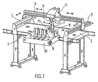
- the workstation is made up of a table 1, carrying an endless moving belt 2 and transversely to each end, a rail 3.
- a traveling crane 4 which itself supports a mobile carriage 5.
- the carriage movable longitudinally on the crane and transversely by the rails 3, is therefore able to cover the entire surface of the workstation.
- Under the carriage 5 is attached to a pivoting lever 6 on which a clamp 7 which itself carries gun 8 intended for the installation of points on the frame, as also shown in Figure 2.
- a positioning cylinder 9 makes it possible to give the clamp, and consequently with the pistol, the inclination sought by relative to band 2 on which is immobilized temporarily frame 14 to be closed.
- a rack 10 On the side of the table 1 is arranged a rack 10, supporting, stored next to each other, a certain number of pistols 8 preloaded with flexible tips.
- the rack is accessible to the gripper 7 carried by the carriage 5, and it is advantageously arranged in front from table 1 and at conveyor belt 2.
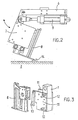
- Figure 3 illustrates more precisely how ensured the attachment of the gun 8 to the clamp 7.
- the latter has two lateral sides 11 forming a vice, between which houses the pistol 8. These sides can open away from each other, side pins 12 providing guidance during this spacing.
- a lever 13 is articulated, actuator of the pistol trigger. Automatic air supply to the pistol is provided with a seal placed on the side of the sealing pliers.
- a first assumption is that the gun has not supplied as it is empty, this being confirmed by counting the peaks posed in relation to the capacity gun.
- the carriage 5 and its pivoting lever 6 are then move, to deposit the empty pistol on the rack 10 and take another full one, then for return to the top of frame 14 at the location of the last tip, to continue the laying cycle.
- a second hypothesis is that there is an anomaly of gun operation, detected by counting raised tips, which do not correspond to the total of tips stored at the start in the pistol. This last can go back to try a pose again, but in the event of further failure the pistol is renewed at rack 10 and replaced by another, as in the case previous.
- the machine thus makes it possible to obtain an hourly rate high of poses of points.
Landscapes
- Engineering & Computer Science (AREA)
- Mechanical Engineering (AREA)
- Life Sciences & Earth Sciences (AREA)
- Forests & Forestry (AREA)
- Automatic Assembly (AREA)
- Portable Nailing Machines And Staplers (AREA)
- Control And Safety Of Cranes (AREA)
- Sewing Machines And Sewing (AREA)
- Automobile Manufacture Line, Endless Track Vehicle, Trailer (AREA)
- Biological Depolymerization Polymers (AREA)
- Soil Working Implements (AREA)
- Guiding Agricultural Machines (AREA)
- Coating Apparatus (AREA)
- Manipulator (AREA)
Abstract
Description
L'invention se situe dans le domaine technique de la fermeture automatisée des cadres et porte plus précisément sur une machine automatique à poser des pointes flexibles. On connait par le DE 4405661 une machine à poser des clous à l'aide d'un système d'enfoncement, les clous provenant d'un magasin de distribution, un détecteur étant apte à signaler l'absence de clous dans le magasin .The invention lies in the technical field of automated closing of the frames and door more precisely on an automatic machine for laying flexible tips. We know from DE 4405661 a machine to install nails to using a driving system, the nails coming from a distribution store, a detector being able to signal the absence of nails in the store.
On connaít aussi divers types de machines adaptées aux cadres dont l'une permet de poser automatiquement une pluralité de pointes flexibles sur les baguettes du cadre pour en assurer la fermeture par un carton. Pour cela, au dessus d'un poste de travail, avantageusement un convoyeur à bande sans fin, un chariot peut se déplacer longitudinalement sur des rails. Il porte un ou plusieurs pistolets, d'agrafage. Chaque pistolet est équipé d'un chargeur de pointes flexibles qu'il convient évidemment de remplacer où de regarnir, en cas d'enrayement ou quand les pointes sont épuisées. Cela implique donc une manipulation manuelle, avec un arrêt provisoire de la machine. Il est aussi possible d'utiliser un dispositif de rechargement automatique des chargeurs, mais cela conduit à des mécanismes lourds et coûteux. En outre ceux-ci ne solutionnent pas les problèmes liés aux incidents de fonctionnement des pistolets. De plus ces machines n'utilisent qu'un ou plusieurs pistolets, chacun d'eux ayant une ou plusieurs pointes à poser à un ou plusieurs endroits déterminés. L'utilisateur doit donc assurer un contrôle visuel et constant de la présence ou de l'absence de pointes. En cas d'absence de pointe il doit déterminer quel pistolet est défaillant, puis arrêter la machine et le remplacer. On encoure le risque, en plus de pertes de productivité, d'obtenir un produit non conforme.We also know various types of machines adapted to frames, one of which automatically sets a plurality of flexible tips on the frame strips to ensure the closure by a carton. For this, at above a work station, preferably a conveyor endless belt, a carriage can move longitudinally on rails. He wears one or more pistols, stapling. Each pistol is equipped with a flexible tip charger that should obviously be replace where to replenish, in case of jamming or when the spikes are exhausted. So this involves manipulation manual, with a temporary stop of the machine. It is also possible to use a recharging device automatic chargers, but this leads to heavy and expensive mechanisms. In addition these do not do not solve problems related to incidents of gun operation. In addition, these machines use only one or more pistols, each of them having one or more points to be placed in one or more places determined. The user must therefore ensure control visual and constant of the presence or absence of tips. If there is no peak, he must determine which gun is faulty, then stop the machine and replace. There is a risk, in addition to loss of productivity, to obtain a non-conforming product.
En vue d'éviter ces inconvénients l'invention propose une solution qui consiste à disposer au voisinage du poste de travail, un râtelier de stockage de pistolets préremplis de pointes flexibles, que la machine viendra chercher au fur et à mesure du dégarnissage du contenu des pistolets au lieu d'utiliser le ou les mêmes pistolets et de les regarnir de pointes.In order to avoid these drawbacks, the invention proposes a solution which consists in having in the vicinity of the station of work, a rack for the storage of pre-filled pistols flexible tips, which the machine will pick up as and as the contents of the pistols are stripped instead use the same gun (s) and refill them with tips.
L'invention a donc pour objet principal une machine automatique à poser des pointes flexibles sur un cadre comportant un chariot mobile porteur d'un pistolet de pose, qui est déplaçable au dessus d'un poste de travail formé d'une table portant une bande sans fin, ledit pistolet renfermant un magasin rempli de pointes à poser et la machine comportant un détecteur de pointes, caractérisée en ce que la machine est équipée d'un râtelier pour le stockage de plusieurs pistolets préremplie de pointes, râtelier qui est accessible à une pince de préhension d'un pistolet, pince portée par ledit chariot, et en ce que le détecteur est monté sur le pistolet pour être en mesure de constater l'absence d'une pointe dans le cadre à l'endroit de la pose, et commande la manoeuvre de la pince en direction du râtelier.The main object of the invention is therefore a machine automatic to place flexible tips on a frame comprising a mobile carriage carrying a laying gun, which is movable above a trained workstation of a table carrying an endless band, said pistol containing a store full of drop-in points and the machine comprising a tip detector, characterized in that the machine is equipped with a rack for the storage of several pre-filled guns with spikes, rack which is accessible to a gripper of a pistol, gripper carried by said carriage, and in that the detector is mounted on the pistol to be able to notice the absence of a point in the frame at the place of installation, and order the operation of the clamp in the direction of the rack.
Des caractéristiques particulières et avantages de
l'invention ressortiront de la description qui va suivre
d'un exemple non limitatif de réalisation dans lequel il est
fait référence aux dessins annexés qui représentent :
Sur la vue d'ensemble de la machine à la figure 1, on
voit que le poste de travail est formé d'une table 1,
portant une bande mobile sans fin 2 et transversalement à
chaque extrémité, un rail 3. Sur ces rails se déplace un
pont roulant 4 qui lui-même supporte un chariot mobile 5. Le
chariot déplaçable longitudinalement sur le pont roulant et
transversalement par les rails 3, est donc apte à couvrir
toute la surface du poste de travail. Sous le chariot 5 est
accroché un levier pivotant 6 sur lequel s'articule une
pince 7 qui elle-même porte pistolet 8 destiné à la pose des
pointes sur le cadre, comme le montre également la figure 2.
Un vérin de positionnement 9 permet de donner à la pince, et
par conséquent au pistolet, l'inclinaison recherchée par
rapport à la bande 2 sur laquelle est immobilisée
temporairement le cadre 14 à fermer.On the overview of the machine in Figure 1, we
sees that the workstation is made up of a table 1,
carrying an
Sur le côté de la table 1 est disposé un râtelier 10,
supportant, rangés les uns à côté des autres, un certain
nombre de pistolets 8 préchargés de pointes flexibles. Le
râtelier est accessible à la pince de préhension 7 portée
par le chariot 5, et il est avantageusement disposé en avant
de la table 1 et au niveau de la bande transporteuse 2.On the side of the table 1 is arranged a
La figure 3 illustre plus précisément comment est
assuré l'accrochage du pistolet 8 à la pince 7. Celle-ci
dispose de deux flancs latéraux 11 formant étau, entre
lesquels vient se loger le pistolet 8. Ces flancs peuvent
s'ouvrir en s'écartant l'un de l'autre, des pions latéraux
12 assurant un guidage lors de cet écartement. Sur un côté
d'un des flancs, s'articule un levier 13, actionneur de la
gâchette du pistolet. Une alimentation automatique d'air au
pistolet est prévue avec un joint placé sur le côté de la
pince pour l'étanchéité.Figure 3 illustrates more precisely how
ensured the attachment of the
On voit à la figure 2 le pistolet 8 incliné et en
appui contre une moulure de cadre 14. La pince tenant le
pistolet possède un petit vérin disposé à l'aplomb de la
pointe et est muni d'un détecteur 15. Le vérin rabat la
pointe sur le carton, en constatant sa présence.We see in Figure 2 the
Si le détecteur (15) constate l'absence d'une pointe
dans le cadre à l'endroit considéré, c'est-à-dire l'endroit
de la pose, une première hypothèse est que le pistolet n'a
pas fourni de pointe car il est vide, ceci étant confirmé
par le comptage des pointes posées par rapport à la capacité
du pistolet. Le chariot 5 et son levier pivotant 6 se
déplacent alors, pour aller déposer le pistolet vide sur le
râtelier 10 et en reprendre un autre plein, puis pour
revenir au dessus du cadre 14 à l'emplacement de la dernière
pointe, afin de poursuivre le cycle de pose.If the detector (15) notices the absence of a tip
in the frame at the location considered, i.e. the location
of the pose, a first assumption is that the gun has
not supplied as it is empty, this being confirmed
by counting the peaks posed in relation to the capacity
gun. The carriage 5 and its
Une seconde hypothèse est qu'il y a une anomalie de
fonctionnement du pistolet, décelée par le comptage des
pointes posées, qui ne correspondent pas au total des
pointes emmagasinées au départ dans le pistolet. Ce dernier
peut revenir en arrière pour essayer à nouveau une pose,
mais en cas de nouvel échec le pistolet est reconduit au
râtelier 10 et remplacé par un autre, comme dans le cas
précédent.A second hypothesis is that there is an anomaly of
gun operation, detected by counting
raised tips, which do not correspond to the total of
tips stored at the start in the pistol. This last
can go back to try a pose again,
but in the event of further failure the pistol is renewed at
Toutes ces manoeuvres sont évidemment gérées par ordinateur, et les informations "pistolet vide" ou "pistolet enrayé" s'affichent sur l'écran de la console de commande.All these maneuvers are obviously managed by computer, and the information "empty gun" or "gun displayed "appear on the display of the control console.
La machine permet ainsi d'obtenir une cadence horaire élevée de poses de pointes.The machine thus makes it possible to obtain an hourly rate high of poses of points.
Claims (4)
- An automatic machine for setting flexible tacks on a frame, comprising a moveable carriage (5) carrying a setting gun (8) which is displaceable above a workstation formed from a table (1) carrying an endless belt (2), the said gun containing a magazine filled with tacks to be set, and the machine comprising a tack detector (15), characterized in that the machine is equipped with a rack (10) for the storage of a plurality of guns (8) prefilled with tacks, the said rack being accessible to a gripper (7) for gripping a gun, and the said gripper being carried by the said carriage (5), and in that the detector (15) is mounted on the gun, so as to be capable of detecting the absence of a tack in the frame at the setting location, and controls the manoeuvre of the gripper in the direction of the rack.
- An automatic machine according to claim 1, characterized in that the gripper (7) has two vice-forming lateral flanks (11), between which the gun (8) is accommodated.
- An automatic machine according to claim 2, characterized in that studs (12) ensure the guidance of the lateral flanks (11) during the spacing-apart of the latter.
- An automatic machine according to claim 1, characterized in that an automatic supply of air to the gun (8) is provided in the region of the gripper (7) by means of a seal.
Applications Claiming Priority (3)
| Application Number | Priority Date | Filing Date | Title |
|---|---|---|---|
| FR0100298 | 2001-01-11 | ||
| FR0100298A FR2819210B1 (en) | 2001-01-11 | 2001-01-11 | AUTOMATIC MACHINE FOR LAYING FLEXIBLE POINTS ON A FRAME |
| PCT/FR2001/004156 WO2002055273A1 (en) | 2001-01-11 | 2001-12-21 | Automated machine for setting flexible nailing points on a frame |
Publications (2)
| Publication Number | Publication Date |
|---|---|
| EP1355769A1 EP1355769A1 (en) | 2003-10-29 |
| EP1355769B1 true EP1355769B1 (en) | 2004-08-04 |
Family
ID=8858679
Family Applications (1)
| Application Number | Title | Priority Date | Filing Date |
|---|---|---|---|
| EP01995759A Expired - Lifetime EP1355769B1 (en) | 2001-01-11 | 2001-12-21 | Automated machine for setting flexible nailing points on a frame |
Country Status (7)
| Country | Link |
|---|---|
| US (1) | US7010851B2 (en) |
| EP (1) | EP1355769B1 (en) |
| AT (1) | ATE272470T1 (en) |
| DE (1) | DE60104725D1 (en) |
| ES (1) | ES2225643T3 (en) |
| FR (1) | FR2819210B1 (en) |
| WO (1) | WO2002055273A1 (en) |
Cited By (1)
| Publication number | Priority date | Publication date | Assignee | Title |
|---|---|---|---|---|
| CN111536412A (en) * | 2020-04-28 | 2020-08-14 | 广东工业大学 | Automatic special liquid adding machine for LNG (liquefied Natural gas) of automobile |
Families Citing this family (11)
| Publication number | Priority date | Publication date | Assignee | Title |
|---|---|---|---|---|
| US7000658B1 (en) * | 2004-01-29 | 2006-02-21 | Harry Soukiassian | Precision adjustable woodworking platform |
| CA2537683A1 (en) * | 2006-02-24 | 2007-08-24 | Luc Williams | Aluminium railings |
| US7954681B2 (en) * | 2007-10-02 | 2011-06-07 | Illinois Tool Works Inc. | Single tool nailing bridge system |
| CN103158124A (en) * | 2011-12-09 | 2013-06-19 | 苏州工业园区高登威科技有限公司 | Machine platform |
| CN103158125A (en) * | 2011-12-09 | 2013-06-19 | 苏州工业园区高登威科技有限公司 | Machine platform |
| CN103158123A (en) * | 2011-12-09 | 2013-06-19 | 苏州工业园区高登威科技有限公司 | Machine platform |
| US9757830B2 (en) * | 2014-12-04 | 2017-09-12 | Ronald P. Allen | Fencing assembly apparatus |
| EP3348368B1 (en) * | 2017-01-13 | 2021-02-03 | Illinois Tool Works, Inc. | Driving module with improved magazine |
| CN108928642B (en) * | 2018-08-17 | 2020-07-10 | 珠海格力智能装备有限公司 | Supporting mechanism |
| CN109732714B (en) * | 2019-01-07 | 2021-08-03 | 深圳市诺亚创盟家具有限公司 | Environment-friendly energy-saving type sofa lean production line lifting adjusting system |
| CN110282416A (en) * | 2019-05-07 | 2019-09-27 | 重庆市盈科物联网信息技术有限公司 | A kind of intelligent machine inspection rack |
Family Cites Families (23)
| Publication number | Priority date | Publication date | Assignee | Title |
|---|---|---|---|---|
| US2743445A (en) * | 1953-03-17 | 1956-05-01 | Swingline Inc | Flexible cartridge or refill for stapling machines |
| US3556316A (en) * | 1967-03-03 | 1971-01-19 | American Mach & Foundry | Quick-change supply system |
| US3590463A (en) * | 1969-03-03 | 1971-07-06 | R K Lebond Machine Tool Co The | Tool changing method |
| US4026453A (en) * | 1976-03-31 | 1977-05-31 | Western Coat Pad Company | Variable work station for pneumatic stapling apparatus |
| IT1135119B (en) * | 1980-01-23 | 1986-08-20 | Jagenberg Werke Ag | PROCEDURE AND DEVICE FOR THE CHANGE OF LABEL CASSETTE-LOADERS IN LABELING MACHINES |
| US4486928A (en) * | 1981-07-09 | 1984-12-11 | Magnavox Government And Industrial Electronics Company | Apparatus for tool storage and selection |
| US4510684A (en) * | 1981-12-08 | 1985-04-16 | Zymark Corporation | Robot tool system |
| US4520550A (en) * | 1983-05-27 | 1985-06-04 | Automated Robotic Systems, Inc. | Robot tool changer |
| US4660274A (en) * | 1985-11-29 | 1987-04-28 | Goumas Peter G | Robot tool changing apparatus |
| US4941577A (en) * | 1988-07-21 | 1990-07-17 | Space Industries Partnership, L.P. | Portable robotic tool rack |
| JP2916021B2 (en) * | 1991-04-18 | 1999-07-05 | オムロン株式会社 | Needleless detector for automatic stapler |
| US5123158A (en) * | 1991-04-26 | 1992-06-23 | Dixon Automatic Tool, Inc. | Automatic assembly machine with coordinately movable fastener driving gun and locating template |
| JPH05212704A (en) * | 1991-06-12 | 1993-08-24 | Matsuda Rojisuteikusu Service Kk | Stapling or nailing device by robot |
| JPH06238608A (en) * | 1993-02-16 | 1994-08-30 | Kinoshita Komuten:Kk | Nailing robot for producing housing panel |
| US5427297A (en) * | 1993-11-09 | 1995-06-27 | Tymianski; Marek | Feeding system for multiple riveting machine |
| DE4405661C2 (en) * | 1994-02-22 | 1998-01-29 | Fraunhofer Ges Forschung | Method and device for mechanical joining of non-metallic workpieces |
| US5463807A (en) * | 1994-09-08 | 1995-11-07 | Scovill Fasteners Inc. | Attaching machine for attaching fasteners |
| US5524807A (en) * | 1994-12-02 | 1996-06-11 | Bullard; Robert | Fastener tool |
| US5667126A (en) * | 1995-03-03 | 1997-09-16 | Boucek; Robert V. | Tool for actuating a pair of fastener ejecting guns |
| IT1278986B1 (en) * | 1995-03-10 | 1997-12-02 | Crea Srl | MACHINE AND PROCEDURE FOR THE PLANTING OF INSERTS IN SHEET PIECES |
| US5716310A (en) * | 1995-11-01 | 1998-02-10 | Excellon Automation Company | Tool change apparatus |
| FR2748225B1 (en) * | 1996-05-03 | 1998-07-31 | Renault Automation | DEVICE FOR STORING TOOLS OF A MACHINE TOOL |
| US5950902A (en) * | 1998-06-10 | 1999-09-14 | Moore, Sr.; George Carlton | Corner bead fastening tool |
-
2001
- 2001-01-11 FR FR0100298A patent/FR2819210B1/en not_active Expired - Fee Related
- 2001-12-21 ES ES01995759T patent/ES2225643T3/en not_active Expired - Lifetime
- 2001-12-21 WO PCT/FR2001/004156 patent/WO2002055273A1/en not_active Application Discontinuation
- 2001-12-21 DE DE60104725T patent/DE60104725D1/en not_active Expired - Lifetime
- 2001-12-21 AT AT01995759T patent/ATE272470T1/en not_active IP Right Cessation
- 2001-12-21 US US10/250,910 patent/US7010851B2/en not_active Expired - Fee Related
- 2001-12-21 EP EP01995759A patent/EP1355769B1/en not_active Expired - Lifetime
Cited By (2)
| Publication number | Priority date | Publication date | Assignee | Title |
|---|---|---|---|---|
| CN111536412A (en) * | 2020-04-28 | 2020-08-14 | 广东工业大学 | Automatic special liquid adding machine for LNG (liquefied Natural gas) of automobile |
| CN111536412B (en) * | 2020-04-28 | 2022-05-20 | 广东工业大学 | Automatic special liquid adding machine for LNG (liquefied Natural gas) of automobile |
Also Published As
| Publication number | Publication date |
|---|---|
| FR2819210A1 (en) | 2002-07-12 |
| FR2819210B1 (en) | 2003-03-28 |
| DE60104725D1 (en) | 2004-09-09 |
| EP1355769A1 (en) | 2003-10-29 |
| WO2002055273A1 (en) | 2002-07-18 |
| US20040144445A1 (en) | 2004-07-29 |
| US7010851B2 (en) | 2006-03-14 |
| ATE272470T1 (en) | 2004-08-15 |
| ES2225643T3 (en) | 2005-03-16 |
Similar Documents
| Publication | Publication Date | Title |
|---|---|---|
| EP1355769B1 (en) | Automated machine for setting flexible nailing points on a frame | |
| EP3237123B1 (en) | Device for separating and singulating heterogeneous postal items | |
| ATE456529T1 (en) | DEVICE FOR HANDLING OBJECTS SUCH AS CARTONS | |
| FR2628021A1 (en) | POWDER ENERGY SEALING APPARATUS | |
| FR2914913A1 (en) | DELIVERY INSTALLATION OF OBJECTS, IN PARTICULAR FOR PHARMACY. | |
| EP3552720B1 (en) | Mail sorting installation with a tray conveyor with retractable edge and shuttle robot for handling trays | |
| EP3858144A1 (en) | Kimchi stuffing adding device, spraying mechanism for kimchi stuffing adding device, and dumping lifter for kimchi stuffing adding device | |
| FR2899213A1 (en) | Object e.g. medicine box, delivering installation e.g. cabinet, for pharmaceutical side room, has drawers with parts each withdrawn magnetically by corresponding electromagnet when electromagnet is activated for displacing selected drawer | |
| US4343390A (en) | Caser unit for containers | |
| EP2354052A1 (en) | Distribution device | |
| JP5497573B2 (en) | Operating device | |
| US20220234128A1 (en) | Welding rod dispenser | |
| CA3010518A1 (en) | Connection device for sheaths by internal gluing, corresponding adhesive rolls and connection methods | |
| CA1320226C (en) | Flat object pile handling device | |
| EP3797650B1 (en) | Storage furniture with storage element and method of use | |
| KR102180671B1 (en) | a cap sealing apparatus | |
| FR2761500A1 (en) | SEMI-AUTOMATIC MACHINE FOR ATTACHING AN ANTI-THEFT DEVICE ON AN ARTICLE, ESPECIALLY FABRIC | |
| KR100391971B1 (en) | robot apparatus for opening envelope | |
| EP3307659A1 (en) | Unstacking device having a viewing system | |
| FR2981242A1 (en) | Piglet identification station, has automatic execution unit for executing controlled crimping around ears of piglets based on identification loops that are formed by male part and female part and automatically transmitted by storage unit | |
| JP3149757B2 (en) | Plate removal equipment | |
| JPS588714Y2 (en) | Can lid automatic feeding device | |
| FR2987772A1 (en) | Distribution line for distribution of flat object i.e. folded flat case, has grip with reception space for objects, where series of objects is selected by suction from space, and reference setting unit for referencing objects in box | |
| USRE24929E (en) | Drapery hook dispensing and inserting apparatus | |
| FR2825342A1 (en) | Labeling machine for supermarket merchandise has rail receiving slide shoe to allow retraction of head into sealable casing |
Legal Events
| Date | Code | Title | Description |
|---|---|---|---|
| PUAI | Public reference made under article 153(3) epc to a published international application that has entered the european phase |
Free format text: ORIGINAL CODE: 0009012 |
|
| 17P | Request for examination filed |
Effective date: 20030715 |
|
| AK | Designated contracting states |
Kind code of ref document: A1 Designated state(s): AT BE CH CY DE DK ES FI FR GB GR IE IT LI LU MC NL PT SE TR |
|
| AX | Request for extension of the european patent |
Extension state: AL LT LV MK RO SI |
|
| RIN1 | Information on inventor provided before grant (corrected) |
Inventor name: CASSESE, PHILIPPE Inventor name: CASSESE, PIERRE Inventor name: CASSESE, JEAN Inventor name: CASSESE, ALAIN |
|
| GRAP | Despatch of communication of intention to grant a patent |
Free format text: ORIGINAL CODE: EPIDOSNIGR1 |
|
| GRAS | Grant fee paid |
Free format text: ORIGINAL CODE: EPIDOSNIGR3 |
|
| GRAA | (expected) grant |
Free format text: ORIGINAL CODE: 0009210 |
|
| AK | Designated contracting states |
Kind code of ref document: B1 Designated state(s): AT BE CH CY DE DK ES FI FR GB GR IE IT LI LU MC NL PT SE TR |
|
| PG25 | Lapsed in a contracting state [announced via postgrant information from national office to epo] |
Ref country code: IE Free format text: LAPSE BECAUSE OF FAILURE TO SUBMIT A TRANSLATION OF THE DESCRIPTION OR TO PAY THE FEE WITHIN THE PRESCRIBED TIME-LIMIT Effective date: 20040804 Ref country code: CY Free format text: LAPSE BECAUSE OF FAILURE TO SUBMIT A TRANSLATION OF THE DESCRIPTION OR TO PAY THE FEE WITHIN THE PRESCRIBED TIME-LIMIT Effective date: 20040804 Ref country code: FI Free format text: LAPSE BECAUSE OF FAILURE TO SUBMIT A TRANSLATION OF THE DESCRIPTION OR TO PAY THE FEE WITHIN THE PRESCRIBED TIME-LIMIT Effective date: 20040804 Ref country code: AT Free format text: LAPSE BECAUSE OF FAILURE TO SUBMIT A TRANSLATION OF THE DESCRIPTION OR TO PAY THE FEE WITHIN THE PRESCRIBED TIME-LIMIT Effective date: 20040804 Ref country code: TR Free format text: LAPSE BECAUSE OF FAILURE TO SUBMIT A TRANSLATION OF THE DESCRIPTION OR TO PAY THE FEE WITHIN THE PRESCRIBED TIME-LIMIT Effective date: 20040804 |
|
| REG | Reference to a national code |
Ref country code: GB Ref legal event code: FG4D Free format text: NOT ENGLISH |
|
| REG | Reference to a national code |
Ref country code: CH Ref legal event code: EP |
|
| REG | Reference to a national code |
Ref country code: IE Ref legal event code: FG4D Free format text: FRENCH |
|
| REF | Corresponds to: |
Ref document number: 60104725 Country of ref document: DE Date of ref document: 20040909 Kind code of ref document: P |
|
| GBT | Gb: translation of ep patent filed (gb section 77(6)(a)/1977) | ||
| PG25 | Lapsed in a contracting state [announced via postgrant information from national office to epo] |
Ref country code: GR Free format text: LAPSE BECAUSE OF FAILURE TO SUBMIT A TRANSLATION OF THE DESCRIPTION OR TO PAY THE FEE WITHIN THE PRESCRIBED TIME-LIMIT Effective date: 20041104 Ref country code: SE Free format text: LAPSE BECAUSE OF FAILURE TO SUBMIT A TRANSLATION OF THE DESCRIPTION OR TO PAY THE FEE WITHIN THE PRESCRIBED TIME-LIMIT Effective date: 20041104 Ref country code: DK Free format text: LAPSE BECAUSE OF FAILURE TO SUBMIT A TRANSLATION OF THE DESCRIPTION OR TO PAY THE FEE WITHIN THE PRESCRIBED TIME-LIMIT Effective date: 20041104 |
|
| PG25 | Lapsed in a contracting state [announced via postgrant information from national office to epo] |
Ref country code: DE Free format text: LAPSE BECAUSE OF FAILURE TO SUBMIT A TRANSLATION OF THE DESCRIPTION OR TO PAY THE FEE WITHIN THE PRESCRIBED TIME-LIMIT Effective date: 20041105 |
|
| PG25 | Lapsed in a contracting state [announced via postgrant information from national office to epo] |
Ref country code: LU Free format text: LAPSE BECAUSE OF NON-PAYMENT OF DUE FEES Effective date: 20041221 |
|
| PG25 | Lapsed in a contracting state [announced via postgrant information from national office to epo] |
Ref country code: MC Free format text: LAPSE BECAUSE OF NON-PAYMENT OF DUE FEES Effective date: 20041231 |
|
| LTIE | Lt: invalidation of european patent or patent extension |
Effective date: 20040804 |
|
| REG | Reference to a national code |
Ref country code: ES Ref legal event code: FG2A Ref document number: 2225643 Country of ref document: ES Kind code of ref document: T3 |
|
| REG | Reference to a national code |
Ref country code: IE Ref legal event code: FD4D |
|
| PLBE | No opposition filed within time limit |
Free format text: ORIGINAL CODE: 0009261 |
|
| STAA | Information on the status of an ep patent application or granted ep patent |
Free format text: STATUS: NO OPPOSITION FILED WITHIN TIME LIMIT |
|
| 26N | No opposition filed |
Effective date: 20050506 |
|
| PG25 | Lapsed in a contracting state [announced via postgrant information from national office to epo] |
Ref country code: CH Free format text: LAPSE BECAUSE OF NON-PAYMENT OF DUE FEES Effective date: 20051231 Ref country code: LI Free format text: LAPSE BECAUSE OF NON-PAYMENT OF DUE FEES Effective date: 20051231 |
|
| PG25 | Lapsed in a contracting state [announced via postgrant information from national office to epo] |
Ref country code: NL Free format text: LAPSE BECAUSE OF NON-PAYMENT OF DUE FEES Effective date: 20060701 |
|
| REG | Reference to a national code |
Ref country code: CH Ref legal event code: PL |
|
| NLV4 | Nl: lapsed or anulled due to non-payment of the annual fee |
Effective date: 20060701 |
|
| PG25 | Lapsed in a contracting state [announced via postgrant information from national office to epo] |
Ref country code: PT Free format text: LAPSE BECAUSE OF NON-PAYMENT OF DUE FEES Effective date: 20050104 |
|
| PGFP | Annual fee paid to national office [announced via postgrant information from national office to epo] |
Ref country code: IT Payment date: 20101127 Year of fee payment: 10 |
|
| PGFP | Annual fee paid to national office [announced via postgrant information from national office to epo] |
Ref country code: ES Payment date: 20111229 Year of fee payment: 11 |
|
| PG25 | Lapsed in a contracting state [announced via postgrant information from national office to epo] |
Ref country code: IT Free format text: LAPSE BECAUSE OF NON-PAYMENT OF DUE FEES Effective date: 20121221 |
|
| REG | Reference to a national code |
Ref country code: ES Ref legal event code: FD2A Effective date: 20140306 |
|
| PG25 | Lapsed in a contracting state [announced via postgrant information from national office to epo] |
Ref country code: ES Free format text: LAPSE BECAUSE OF NON-PAYMENT OF DUE FEES Effective date: 20121222 |
|
| PGFP | Annual fee paid to national office [announced via postgrant information from national office to epo] |
Ref country code: GB Payment date: 20141223 Year of fee payment: 14 |
|
| PGFP | Annual fee paid to national office [announced via postgrant information from national office to epo] |
Ref country code: FR Payment date: 20141230 Year of fee payment: 14 |
|
| PGFP | Annual fee paid to national office [announced via postgrant information from national office to epo] |
Ref country code: BE Payment date: 20141231 Year of fee payment: 14 |
|
| PG25 | Lapsed in a contracting state [announced via postgrant information from national office to epo] |
Ref country code: BE Free format text: LAPSE BECAUSE OF NON-PAYMENT OF DUE FEES Effective date: 20151231 |
|
| GBPC | Gb: european patent ceased through non-payment of renewal fee |
Effective date: 20151221 |
|
| REG | Reference to a national code |
Ref country code: FR Ref legal event code: ST Effective date: 20160831 |
|
| PG25 | Lapsed in a contracting state [announced via postgrant information from national office to epo] |
Ref country code: GB Free format text: LAPSE BECAUSE OF NON-PAYMENT OF DUE FEES Effective date: 20151221 |
|
| PG25 | Lapsed in a contracting state [announced via postgrant information from national office to epo] |
Ref country code: FR Free format text: LAPSE BECAUSE OF NON-PAYMENT OF DUE FEES Effective date: 20151231 |