EP1355084A1 - Wheel balance weight and process for manufacturing the same - Google Patents
Wheel balance weight and process for manufacturing the same Download PDFInfo
- Publication number
- EP1355084A1 EP1355084A1 EP03008924A EP03008924A EP1355084A1 EP 1355084 A1 EP1355084 A1 EP 1355084A1 EP 03008924 A EP03008924 A EP 03008924A EP 03008924 A EP03008924 A EP 03008924A EP 1355084 A1 EP1355084 A1 EP 1355084A1
- Authority
- EP
- European Patent Office
- Prior art keywords
- weight
- zinc
- wheel
- wheel balance
- balance weight
- Prior art date
- Legal status (The legal status is an assumption and is not a legal conclusion. Google has not performed a legal analysis and makes no representation as to the accuracy of the status listed.)
- Granted
Links
- 238000004519 manufacturing process Methods 0.000 title claims abstract description 37
- 238000000034 method Methods 0.000 title claims description 12
- 230000008569 process Effects 0.000 title claims description 8
- HCHKCACWOHOZIP-UHFFFAOYSA-N Zinc Chemical compound [Zn] HCHKCACWOHOZIP-UHFFFAOYSA-N 0.000 claims abstract description 81
- 239000011701 zinc Substances 0.000 claims abstract description 81
- 229910052725 zinc Inorganic materials 0.000 claims abstract description 81
- 229910045601 alloy Inorganic materials 0.000 claims abstract description 41
- 239000000956 alloy Substances 0.000 claims abstract description 41
- 238000009434 installation Methods 0.000 claims abstract description 24
- 230000002093 peripheral effect Effects 0.000 claims description 27
- 239000000853 adhesive Substances 0.000 claims description 22
- 230000001070 adhesive effect Effects 0.000 claims description 22
- JEIPFZHSYJVQDO-UHFFFAOYSA-N iron(III) oxide Inorganic materials O=[Fe]O[Fe]=O JEIPFZHSYJVQDO-UHFFFAOYSA-N 0.000 claims description 13
- 230000002265 prevention Effects 0.000 claims description 13
- 238000003825 pressing Methods 0.000 claims description 8
- RYGMFSIKBFXOCR-UHFFFAOYSA-N Copper Chemical compound [Cu] RYGMFSIKBFXOCR-UHFFFAOYSA-N 0.000 claims description 5
- ATJFFYVFTNAWJD-UHFFFAOYSA-N Tin Chemical compound [Sn] ATJFFYVFTNAWJD-UHFFFAOYSA-N 0.000 claims description 5
- XAGFODPZIPBFFR-UHFFFAOYSA-N aluminium Chemical compound [Al] XAGFODPZIPBFFR-UHFFFAOYSA-N 0.000 claims description 5
- 229910052802 copper Inorganic materials 0.000 claims description 5
- 239000010949 copper Substances 0.000 claims description 5
- 229910052782 aluminium Inorganic materials 0.000 claims description 4
- 238000005266 casting Methods 0.000 claims description 4
- 239000012535 impurity Substances 0.000 claims description 4
- 239000011248 coating agent Substances 0.000 claims description 2
- 238000000576 coating method Methods 0.000 claims description 2
- 229910001297 Zn alloy Inorganic materials 0.000 description 10
- 238000005520 cutting process Methods 0.000 description 5
- 239000007769 metal material Substances 0.000 description 4
- 239000004925 Acrylic resin Substances 0.000 description 3
- 229920000178 Acrylic resin Polymers 0.000 description 3
- 230000008901 benefit Effects 0.000 description 3
- 239000000463 material Substances 0.000 description 3
- 230000007797 corrosion Effects 0.000 description 2
- 238000005260 corrosion Methods 0.000 description 2
- 241001163841 Albugo ipomoeae-panduratae Species 0.000 description 1
- 230000009471 action Effects 0.000 description 1
- 239000002390 adhesive tape Substances 0.000 description 1
- 230000002411 adverse Effects 0.000 description 1
- 238000005452 bending Methods 0.000 description 1
- 230000015556 catabolic process Effects 0.000 description 1
- 238000006388 chemical passivation reaction Methods 0.000 description 1
- 238000010273 cold forging Methods 0.000 description 1
- 238000006731 degradation reaction Methods 0.000 description 1
- 230000000593 degrading effect Effects 0.000 description 1
- 230000000694 effects Effects 0.000 description 1
- 230000005484 gravity Effects 0.000 description 1
- 230000001771 impaired effect Effects 0.000 description 1
- 229910052751 metal Inorganic materials 0.000 description 1
- 239000002184 metal Substances 0.000 description 1
- 239000000203 mixture Substances 0.000 description 1
- 230000004048 modification Effects 0.000 description 1
- 238000012986 modification Methods 0.000 description 1
- 230000002035 prolonged effect Effects 0.000 description 1
- 238000004080 punching Methods 0.000 description 1
- 238000005096 rolling process Methods 0.000 description 1
- 239000007779 soft material Substances 0.000 description 1
Images


Classifications
-
- F—MECHANICAL ENGINEERING; LIGHTING; HEATING; WEAPONS; BLASTING
- F16—ENGINEERING ELEMENTS AND UNITS; GENERAL MEASURES FOR PRODUCING AND MAINTAINING EFFECTIVE FUNCTIONING OF MACHINES OR INSTALLATIONS; THERMAL INSULATION IN GENERAL
- F16F—SPRINGS; SHOCK-ABSORBERS; MEANS FOR DAMPING VIBRATION
- F16F15/00—Suppression of vibrations in systems; Means or arrangements for avoiding or reducing out-of-balance forces, e.g. due to motion
- F16F15/32—Correcting- or balancing-weights or equivalent means for balancing rotating bodies, e.g. vehicle wheels
- F16F15/324—Correcting- or balancing-weights or equivalent means for balancing rotating bodies, e.g. vehicle wheels the rotating body being a vehicle wheel
- F16F15/328—Multiple weights on adhesive strip
Definitions
- the present invention relates to a wheel balance weight.
- a wheel balance weight which is installed to an inner peripheral surface of a rim in a wheel of a vehicle.
- the wheel is equipped with a wheel balance weight, which can cancel the imbalance.
- the installation position of the wheel balance weight to the wheel and the mass of the wheel balance weight are determined by measuring the imbalance of the wheel assembly with a special purpose measuring apparatus.
- a wheel balance weight which is installed to an inner peripheral surface of a rim in the wheel by bonding a substantially plate-shaped weight, having a predetermined mass, by means of an adhesive tape, etc.
- the weight When the conventional wheel balance weight is manufactured, the weight is formed as a flat plate shape. When it is installed to the wheel, the weight is curved along the inner peripheral surface of the rim in the wheel. Moreover, since the curvature of the conventional wheel balance weight depends on the curvature of the wheels to which it is installed, it is determined appropriately.
- the weight has been formed of lead, which is one of soft materials.
- the weight, which is formed of lead can be readily processed, and can be readily curved with a manual labor.
- the present invention has been developed in view of the aforementioned circumstances. It is therefore an object of the present invention to provide a wheel balance weight, which puts a less load onto environment when it is abolished.
- the inventors of the present invention repeatedly investigated the materials of the weight. As a result, they found out that it is possible to achieve the object by making a weight which is composed of zinc or a zinc-based alloy. Thus, they completed the present invention.
- a wheel balance weight according to the present invention is characterized in that it comprises:
- the weight is composed of zinc or a zinc-based alloy which puts a less load onto environment. Therefore, even when the present wheel balance weight is abolished, the surrounding environments are inhibited from being polluted. Moreover, zinc or a zinc-based alloy exhibits a relatively low temperature so that it can be readily processed. Hence, it is possible to manufacture the present wheel balance weight at reduced costs and install it to wheels with ease.
- a manufacturing process according to the present invention is adapted for manufacturing the present wheel balance weight, and is characterized in that it comprises the steps of:
- the present wheel balance weight which comprises the weight being composed of zinc or a zinc-based alloy.
- zinc or a zinc-based alloy puts a less load onto environment, and can be readily processed. Therefore, in accordance with the present manufacturing process, it is possible to manufacture the present wheel balance weight, which puts a less load onto environment, with ease.
- a wheel balance weight according to the present invention comprises a weight and installation means.
- the weight is composed of at least one member selected from the group consisting of zinc and a zinc-based alloy, is formed as a substantially strip shape having a substantially uniform thickness, and has opposite surfaces and at least a groove. The groove is formed in at least one of the opposite surfaces of the weight, and crosses in the width-wise direction of the weight.
- the installation means is adapted for installing the weight to a rim in a wheel.
- the weight is composed of zinc or a zinc-based alloy which puts a less load onto environment. Therefore, even when the present wheel balance weight is abolished, the surrounding environments are inhibited from being polluted.
- zinc or a zinc-based alloy exhibits a relatively low temperature so that it can be readily processed. Hence, it is possible to manufacture the present wheel balance weight at reduced costs and install it to wheels with ease.
- zinc or a zinc-based alloy constitutes the weight.
- Zinc herein refers to pure zinc.
- the zinc-based alloy herein refers to alloys in which zinc makes a major component substantially.
- the zinc-based alloy refers to zinc alloys whose zinc content is 39.5% by weight or more when the entirety is taken as 100% by weight.
- the zinc content can further preferably be 45% by weight or more, furthermore preferably be 50% by weight or more, moreover preferably be 90% by weight or more.
- the weight can preferably be composed of a zinc-based alloy which comprises tin in an amount of less than 50% by weight, copper in an amount of less than 5% by weight, aluminum in an amount of less than 5% by weight, and the balance of zinc and inevitable impurities.
- the content of tin can further preferably be from 0 to 50% by weight, furthermore preferably be from 0 to 0.01% by weight.
- the content of copper can further preferably be from 0 to 5% by weight, furthermore preferably be from 0 to 1% by weight.
- the content of aluminum can further preferably be from 0 to 4.5% by weight, furthermore preferably be from 3.5 to 4.5% by weight.
- the content of inevitable impurities can be less than 1.5% by weight, further preferably be less than 0.5% by weight.
- the weight when the weight is composed of zinc or the zinc-based alloy, the weight exhibits corrosion resistance of itself by the formation of passive films or the sacrificial rust prevention action.
- the passive films are composed of dense oxide films.
- the weight has at least a groove, which is formed in at least one the opposite surfaces of the weight and which crosses in the width-wise direction. Since the weight has the groove, the thickness of the weight is reduced partially at the portion in which the groove is formed. In other words, the weight exhibits a lowered rigidity at the portion in which the groove is formed than at the other portions which are free from the groove or which have a larger thickness. Accordingly, when the present wheel balance weight is curved along a curved inner peripheral surface of a rim in a wheel in order to install the present wheel balance weight to the wheel, the weight can be bent at the portion in which the groove is formed. Thus, a curved shape is formed which goes along the inner peripheral surface of the rim in the wheel. Consequently, when the present wheel balance weight is installed to the wheel, it is possible to carry out the installation by curving the weight with a less force.
- the groove can be formed in the opposite top surface of the weight, or can be formed in the opposite bottom surface thereof.
- the groove can be formed in both of the opposite top and bottom surfaces.
- the opposite top surface of the weight herein means one of the opposite surfaces of the weight which faces radially inwardly the axial center of the wheel when the present wheel balance weight is installed to the wheel
- the opposite bottom surface of the weight herein means the other one of the opposite surfaces of the weight which faces the wheel radially outwardly, or which contacts with the inner peripheral surface of the rim in the wheel, when the present wheel balance weight is installed to the wheel.
- the groove can preferably be formed in the opposite bottom surface of the weight.
- the groove is formed in the opposite bottom surface of the weight, it is possible to readily curve the weight along the inner peripheral surface of the rim in the wheel in installing the present wheel balance weight to the wheel.
- the weight is curved, it is compressed on the opposite top surface side, and is extended on the opposite bottom surface side.
- the width of the groove is widened when the weight is curved.
- the width of the groove is widened, the length of the weight is prolonged on the opposite bottom-surface side of the weight. This phenomenon implies that the weight is not adversely affected by the ductility of zinc or the zinc-based alloy which makes the weight, and that the weight can be curved with a reduced force as well.
- the groove is formed in the opposite bottom surface of the weight, it is possible to make the opposite top surface of the wheel smooth or free from irregularities.
- the weight is formed substantially as a strip shape having a substantially uniform thickness.
- the thickness of the weight herein refers to the thickness of the portions of the weight which are free from the groove.
- the thickness of the weight is not limited in particular. Namely, the thickness can be a thickness which gives a desired mass to the weight.
- the thickness of the weight is substantially uniform, it is possible to adjust the mass of the weight with ease. For example, when the dimensions of the weight are adjusted in the width-wise and longitudinal directions, it is possible to give a desired mass to the weight.
- the present wheel balance weight is installed to wheels with improved installation property. Namely, since the present wheel balance weight hardly requires excessive installation spaces in the thickness-wise direction when it is installed to wheels, it can be installed to a variety of wheels. Specifically, along with the recent trend of developing high-performance vehicle, the performance of the brake system has been improved as the power output is improved. As one of the improvements on the brake system performance, it has been intended to diametrically enlarge brakes. The diametric enlargement of brakes results in the decrement of the space between the inner peripheral surface of wheels and the outer peripheral surface of brakes (i.e., the installation space for wheel balance weights) within wheels. However, since the weight of the present wheel balance weight has a substantially uniform thickness, it is possible to install the present wheel balance weight without being interfered by brakes even when it is disposed at radially outwardly with respect to brakes.
- the installation means is not limited in particular as far as it can install the weight to a rim in a wheel.
- the installation means can be the same means as a variety of installation means which have been used to install conventional wheel balance weights. Specifically, it is possible to name a clip which hooks the weight at peripheral ends of a rim in a wheel, and a double-sided tape which bonds the weight with a rim in a wheel.
- the installation means can preferably be a double-sided tape which has opposite adhesive surfaces, which are disposed back to back with each other. One of the adhesive surfaces is to be bonded onto the weight. The other one of the adhesive surfaces is to be bonded onto a rim in a wheel.
- the installation means is such a double-sided tape, it is possible to install the present wheel balance weight to an inner peripheral surface of a rim in a wheel so that the appearance of the wheel is not impaired.
- a less expensive double-sided tape is used as the installation means, it is possible to reduce the material costs of the present wheel balance weight.
- such a double-sided tape enables the present wheel balance weight to produce advantage in that no special devices are needed when the present wheel balance weight is installed to wheels.
- the cross sectional shape of the groove is not limited in particular, either.
- the cross sectional shape of the groove can be shapes which enable the weight to curve along an inner peripheral surface of a rim in a wheel when the present wheel balance is installed to the wheel.
- the cross sectional shape of the groove refers to the cross sectional shape in the perpendicular direction with resect to the extending direction of the groove.
- the cross sectional shape of the groove it is possible to name such shapes as a substantially letter "V" shape (see Fig. 2), a substantially letter "U” shape (see Fig. 9), and a squarely dented shape (see Fig. 10).
- the cross sectional shape of the groove can further preferably be such that the width at the opening is greater than the width at the bottom.
- the weight can preferably be provided with a rust prevention film on the opposite top and bottom surfaces at least.
- a rust prevention film When the weight is provided with a rust prevention film, the weight is inhibited from rusting.
- the weight is inhibited from degrading the appearance. The appearance degradation is caused by the white rust which is generated when the weight being composed of zinc or the zinc-based alloy is oxidized.
- the rust prevention film is not limited in particular.
- the rust prevention film can preferably be an acrylic resin film 5 as illustrated in Fig. 11, because such an acrylic resin film 5 can upgrade the appearance of the weight.
- the acrylic resin film 5 can further preferably be a metallic color film.
- the weight can preferably be curved so as to go along an inner peripheral surface of a rim in a wheel.
- the weight is curved so as to go along an inner peripheral surface of rim in a wheel” herein designates that the weight is curved at portions in which no groove is formed.
- the weight of the present wheel balance weight is curved so as to go along an inner peripheral surface of a rim in a wheel, it is possible to install the present wheel balance weight to the inner peripheral surface with ease.
- an identification mark to the opposite top surface of the weight of the present wheel balance weight.
- the opposite top surface is marked with a mass of the weight, it is possible to readily identify and select a weight which has a desired mass. It is not limited, either, in terms of the way to give the identification mark to the opposite top surface of the weight.
- a process for manufacturing a wheel balance weight according to the present invention comprises a weight forming step and a double-sided tape applying step.
- a weight is formed.
- the resulting weight is composed of at least one member selected from the group consisting of zinc and a zinc-based alloy, is formed as a substantially strip shape having a substantially uniform thickness, and has opposite surfaces and at least a groove.
- the groove is formed in at least one of the opposite surfaces of the weight, and crosses in the width-wise direction of the weight.
- a double-sided tape, having opposite adhesive surfaces is applied to the weight so as to adhere one of the opposite adhesive surfaces onto one of the opposite surfaces of the weight.
- the present wheel balance weight which comprises the weight being composed of zinc or the zinc-based alloy.
- zinc or the zinc-based alloy puts a less load onto environment, and can be readily processed. Therefore, in accordance with the present manufacturing process, it is possible to manufacture the present wheel balance weight, which puts a less load onto environment, with ease.
- the weight forming step and the double-sided tape applying step are not limited in particular.
- the weight forming step and the double-sided tape applying step it is possible to use means which have been used in manufacturing conventional wheel balance weights. Except for zinc or the zinc-based alloy making the weight, materials used in the present manufacturing process are not limited, either.
- the weight forming step can preferably be a step of manufacturing the weight by casting zinc or the zinc-based alloy. Specifically, when the weight is formed by casting, it is possible to form the weight having a desired shape with ease. Moreover, since the weight is composed of the zinc-based alloy, it is possible to manufacture the weight by pouring a molten metal, in which raw metallic materials are solved, into a mold having cavities with a desired shape. Thus, it is possible to readily manufacture the weight having a desired shape.
- the weight forming step can preferably be a step of forming the weight by pressing a plate-shaped member being composed of zinc or the zinc-based member. Since the weight is formed by pressing, the formed weight is improved in terms of the dimensional accuracy. As a result, it is possible to readily cancel the imbalance in wheels with the present wheel balance weight. Specifically, when the dimensional accuracy is upgraded, it is easy to find the center of gravity in the present wheel balance weight. Accordingly, it is possible to install the present wheel balance to wheels with enhanced installation accuracy. In addition, when the entire weight is subjected to pressing forming, the weight is compressed to enlarge the density. When the density is enlarged, it is possible to reduce the size of the weight.
- the press forming in the weight forming step is not limited in particular as far as it is a method in which the weight can be formed by compressing a plate-shaped or wire-shaped member.
- the press forming in the weight forming step is not limited in particular as far as it is a method in which the weight can be formed by compressing a plate-shaped or wire-shaped member.
- such means as cold forging, punching, cutting and stamping.
- the way to form the groove in the weight is not limited in particular, either.
- a mold in the casting, a mold can be provided with a protrusion which has been formed in advance to correspond to the groove, and the weight having the groove can be cast with the mold; and the groove can be formed by pressing a plate-shaped zinc or zinc-based alloy plate to dent it partially.
- one of the opposite adhesive surfaces of a double-sided tape can preferably be bonded onto one of the opposite surfaces of the weight.
- one of the opposite adhesive surfaces of a double-sided tape is bonded onto one of the opposite surfaces of the weight, it is possible to readily manufacture the present wheel balance whose weight is assembled with a wheel by using the double-sided tape.
- the present manufacturing process can preferably further comprise a film forming step, in which a rust prevention film is formed on the opposite surfaces at least, before carrying out the double-sided tape applying step.
- a film forming step in which a rust prevention film is formed on the opposite surfaces at least, before carrying out the double-sided tape applying step.
- the present manufacturing step can preferably further comprise a pre-treating step, in which the opposite surfaces of the weight cleansed, before carrying out the rust prevention film forming step.
- a pre-treating step in which the opposite surfaces of the weight cleansed, before carrying out the rust prevention film forming step.
- the present manufacturing process can preferably further comprises a step of giving an identification mark to the opposite top surface of the weight.
- the way to give an identification mark to the opposite top surface of the weight is not limited in particular, either.
- the present manufacturing step can preferably further comprise a weight cutting step in which the weight is cut to a predetermined length.
- a weight cutting step in which the weight is cut to a predetermined length.
- the weight cutting step can be carried out at any time as far as it is carried out after the weight forming step. However, the cutting step can further preferably be carried out after carrying out a groove forming step.
- the weight cutting step is carried out after a groove forming step, it is possible to cut the weight, which is composed of zinc or the zinc-based alloy, with ease. Specifically, it is possible to cut the weight at the groove whose thickness is thinner than the other portions.
- Example No. 1 a wheel balance weight as illustrated in Figs. 1 through 4 was manufactured.
- the manufacturing method of the wheel balance weight of Example No. 1 will be hereinafter described with reference to Figs. 1 through 4.
- metallic materials such as metallic zinc, metallic tin, metallic copper and metallic aluminum
- the metallic materials were weighed by a predetermined amount, respectively.
- the metallic materials were charged into a crucible, and were heated.
- the metallic materials were melted to prepare a molten alloy.
- the molten alloy contained zinc in an amount of 95% by weight, tin in an amount of 0.01% by weight, copper in an amount of 1% by weight, aluminum in an amount of 3.84% by weight, and the inevitable impurities in an amount of less than 0.15% by weight.
- the molten alloy was poured into a mold to manufacture a strip-shaped weight 2.
- a plurality of grooves 21 were formed in one of the opposite surfaces of the weight 2.
- the grooves 21 crossed in the width-wise direction of the weight 2.
- the grooves 21 formed in the weight 2 had a letter "V"-shaped cross section when they were cut in the longitudinal direction of the weight 2 (or viewed in the direction perpendicular to the longitudinal direction of the weight 2).
- the weight 2 was curved.
- the weight 2 was curbed by such means as pressing and rolling.
- the weight 2 was curved with a die so that it substantially conformed to a curved shape of an inner peripheral surface of a rim in a wheel when it was installed to the wheel.
- the weight 2 was curved so that the opposite surface with the grooves 21 formed faced inwardly in the radial direction of the wheel.
- the other curving method was tried in which a curved portion had been provided in a mold in advance and a weight was formed with the mold.
- One of the opposite adhesive surfaces of a double-sided tape 2 was adhered onto the other one of the opposite surfaces of the curved weight 2 in which no groove 21 was formed, or onto the opposite bottom surface of the curved weight 2 which was to face a rim in a wheel radially outwardly. Note that the weight 2 was inhibited from adhering to places other than a wheel when it was handled, because the other one of the opposite adhesive surfaces of the double-sided tape 3 was covered with a separator paper 31.
- the wheel balance weight 1 of Example No. 1 was manufactured.
- Example No. 1 The wheel balance weight 1 of Example No. 1 was actually installed to a wheel by the following procedure.
- Fig. 5 illustrates how the wheel balance weight 1 was installed to an inner peripheral surface of a rim in a wheel 4.
- the separator paper 31 was removed from the wheel balance weight 1 of Example No. 1 to expose the other opposite adhesive surface of the double-sided tape 3. Subsequently, the exposed opposite adhesive surface was bonded to a predetermined position in an inner peripheral surface of a rim in the wheel 4 to install the wheel balance weight 1 to the wheel 4. In this instance, it was possible to snugly fit the contacting portions of the weight 2 to the curved shape of the wheel 4 by pressing the weight 2 onto the rim in the wheel 4.
- the weight 2 was curved more than the curvature of the inner peripheral surface of the rim in the wheel 4. Accordingly, when the wheel balance weight 1 was installed to the wheel 4, the curved weight 2 was pressed to snugly fit to the curved inner peripheral surface of the rim in the wheel 4. In this instance, the letter "V"-shaped grooves 21, which were formed in the opposite top surface of the weight 2, were contracted so that the weight 2 was fitted snugly to the wheel 4.
- Example No. 2 a wheel balance weight 1 as illustrated in Fig. 6 was manufactured.
- the wheel balance weight 1 is provided with a plate-shaped weight 2 in which grooves 21 having a letter "U"-shaped cross section were formed in one of the opposite surfaces.
- the weight 2 was manufactured by press working.
- a zinc alloy plate which had the same alloy composition as that of the weight 2 of the wheel balance weight 1 of Example No. 1 was first cut to a strip shape. Then, the strip-shaped zinc alloy plate was pressed by a punch which had a predetermined shape to manufacture the weight 2 which was provided with the grooves 21 in one of the opposite surfaces of the strip-shaped zinc alloy plate.
- the grooves 21 herein had a letter "U"-shaped cross section, and crossed in the width-wise direction of the strip-shaped weight 2.
- Example No. 2 was manufactured.
- Fig. 6 illustrates the resulting wheel balance weight 1 of Example No. 2.
- the wheel balance weight 1 of Example No. 2 could be installed to a wheel in the same manner as the wheel balance weight 1 of Example No. 1.
- a wheel balance weight 1 of Example No. 3 is a modified version of the wheel balance weight 1 of Example No. 2. Except that the grooves 21 had a letter "V"-shaped cross section, and that the portions of the weight 2 disposed between the respective grooves 21 were curved independently, the wheel balance weight 1 of Example No. 3 was the same as the wheel balance weight 1 of Example No. 2.
- a zinc alloy plate was cut to a strip shape in the same manner as Example No. 2. Then, a punch having a predetermined shape was pressed onto one of the opposite surfaces of the strip-shaped zinc alloy plate to form the grooves 21 which crossed in the width-wise direction of the weight 2 and which had a letter "V"-shaped cross section. Thereafter, the portions of the strip-shaped zinc plate disposed between the respective grooves 21 were curved independently by press forming. Finally, the strip-shaped zinc plate was cut to a predetermined length to manufacture the weight 2.
- Fig. 7 illustrates the resulting wheel balance weight 1 of Example No. 3.
- the wheel balance weight 1 of Example No. 3 could be installed to a wheel in the same manner as the wheel balance weight 1 of Example No. 1.
- Example No. 4 was the same as the wheel balance weight 1 of Example No. 3.
- a zinc alloy plate was cut to a strip shape in the same manner as Example No. 3. Then, a punch having a predetermined shape was pressed onto one of the opposite surfaces of the strip-shaped zinc alloy plate to form the grooves 21 which crossed in the width-wise direction of the weight 2 and which had a letter "V"-shaped cross section. Thereafter, the portions of the strip-shaped zinc plate disposed between the respective grooves 21 were curved independently by press forming. Finally, the strip-shaped zinc plate was cut to a predetermined length to manufacture the weight 2.
- Example No. 4 note that the punch, which was pressed onto one of the opposite surfaces of the zinc alloy plate, was formed so that it had different shapes at the central portion than at the opposite ends in the leading end surface. Specifically, the resulting grooves 21 had a larger width at the central portion than at the opposite ends. Moreover, the grooves 21 were formed so that the width varied from wide to narrow in the width-wise direction outwardly from the central portion to the opposite ends.
- the deformation magnitude of the texture at the central portion in the zinc alloy plate differed from the deformation magnitudes of the textures at the opposite ends therein. Accordingly, when the texture was moved by a plastic deformation from the central portion to the opposite ends, the textures at the opposite ends could absorb the texture, which was moved from the central portion. As a result, it was possible to inhibit the burrs, flashes, and so forth, which would have protruded in the width-wise direction, from taking place.
- one of the opposite adhesive surfaces of a double-sided tape 2 was adhered onto one of the opposite surfaces of the weight 2 in which the grooves 21 were formed, or onto the opposite bottom surface of the weight 2 which was to face a rim in a wheel radially outwardly.
- Fig. 8 illustrates the resulting wheel balance weight 1 of Example No. 4.
- Example No. 4 In the same manner as the wheel balance weight 1 of Example Nos. 1 through 3, it was possible to install the wheel balance weight 1 of Example No. 4 by pressing the other one of the opposite adhesive surfaces of the double-sided tape 2 onto a predetermined position in an inner peripheral surface of a rim in a wheel. Note that, prior to the installation of the wheel balance weight 1 of Example No. 4 to a wheel, the wheel balance weight 1 was cut to adjust the mass of the wheel balance weight 1 to a desired mass. Specifically, the wheel balance weight 1 was cut by repeatedly bending the weight 2 back and forth at one of the grooves 21 until the weight 2 broke at the groove 21.
- Example No. 4 When the wheel balance weight 1 of Example No. 4 was pressed onto an inner peripheral surface of a rim in a wheel to install it to the wheel, the weight 2 was subjected to a stress, which expanded the weight 2 in the longitudinal direction, on the opposite bottom surface side, and another stress, which compressed the weight 2 in the longitudinal direction, on the opposite top surface side.
- the width of the grooves 21 was enlarged on the opposite bottom surface side.
- the weight 2 was curved so as to snugly fit to the curvature of the inner peripheral surface of the rim in the wheel. Simultaneously therewith, the weight 2 was adhered and fastened to the inner peripheral surface of the rim in the wheel.
- a wheel balance weight includes a weight and an installation member.
- the weight is composed of at least one member selected from the group consisting of zinc and a zinc-based alloy, is formed as a substantially strip shape having a substantially uniform thickness, and has opposite surfaces and at least a groove. The groove is formed in at least one of the opposite surfaces of the weight, and crosses in the width-wise direction of the weight.
- the installation member is adapted for installing the weight to a rim in a wheel. Since the weight is composed of zinc or a zinc-based alloy, environments are inhibited from being polluted when the wheel balance weight is abolished. Moreover, it is possible to manufacture the wheel balance weight at reduced costs and install it to wheels with ease.
Landscapes
- Engineering & Computer Science (AREA)
- General Engineering & Computer Science (AREA)
- Physics & Mathematics (AREA)
- Acoustics & Sound (AREA)
- Aviation & Aerospace Engineering (AREA)
- Mechanical Engineering (AREA)
- Forging (AREA)
- Golf Clubs (AREA)
- Tires In General (AREA)
- Testing Of Balance (AREA)
Abstract
Description
- The present invention relates to a wheel balance weight. In particular, it relates to a wheel balance weight which is installed to an inner peripheral surface of a rim in a wheel of a vehicle.
- In a wheel-assembled state; namely: in a state where a tire of an automobile, or the like, is assembled with a wheel, there arises a drawback in that, as the imbalance enlarges in the peripheral direction around the rotary shaft of the wheel assembly as well as in the direction of the rotary shaft of the wheel assembly, the vibrations, noises, and the like, generate when driving a vehicle.
- The vibrations, noises, and so on, result from the imbalance in the wheel. Accordingly, the wheel is equipped with a wheel balance weight, which can cancel the imbalance. The installation position of the wheel balance weight to the wheel and the mass of the wheel balance weight are determined by measuring the imbalance of the wheel assembly with a special purpose measuring apparatus.
- As one of the conventional wheel balance weights, there has been, for example, a wheel balance weight, which is installed to an inner peripheral surface of a rim in the wheel by bonding a substantially plate-shaped weight, having a predetermined mass, by means of an adhesive tape, etc.
- When the conventional wheel balance weight is manufactured, the weight is formed as a flat plate shape. When it is installed to the wheel, the weight is curved along the inner peripheral surface of the rim in the wheel. Moreover, since the curvature of the conventional wheel balance weight depends on the curvature of the wheels to which it is installed, it is determined appropriately.
- In the conventional wheel balance weight, the weight has been formed of lead, which is one of soft materials. The weight, which is formed of lead, can be readily processed, and can be readily curved with a manual labor.
- However, it has been known that lead puts a large load onto environment when it is abolished.
- The present invention has been developed in view of the aforementioned circumstances. It is therefore an object of the present invention to provide a wheel balance weight, which puts a less load onto environment when it is abolished.
- In order to carry out the object, the inventors of the present invention repeatedly investigated the materials of the weight. As a result, they found out that it is possible to achieve the object by making a weight which is composed of zinc or a zinc-based alloy. Thus, they completed the present invention.
- For example, a wheel balance weight according to the present invention is characterized in that it comprises:
- a weight being composed of at least one member selected from the group consisting of zinc and a zinc-based alloy, being formed as a substantially strip shape having a substantially uniform thickness, and having opposite surfaces and at least a groove, the groove being formed in at least one of the opposite surfaces of the weight and crossing in the width-wise direction thereof; and
- installation means for installing the weight to a rim in a wheel.
-
- In the present wheel balance weight, the weight is composed of zinc or a zinc-based alloy which puts a less load onto environment. Therefore, even when the present wheel balance weight is abolished, the surrounding environments are inhibited from being polluted. Moreover, zinc or a zinc-based alloy exhibits a relatively low temperature so that it can be readily processed. Hence, it is possible to manufacture the present wheel balance weight at reduced costs and install it to wheels with ease.
- A manufacturing process according to the present invention is adapted for manufacturing the present wheel balance weight, and is characterized in that it comprises the steps of:
- forming a weight being composed of at least one member selected from the group consisting of zinc and a zinc-based alloy, being formed as a substantially strip shape having a substantially uniform thickness, and having opposite surfaces and at least a groove, the groove being formed in at least one of the opposite surfaces of the weight and crossing in the width-wise direction thereof; and
- applying a double-sided tape, having opposite adhesive surfaces, to the weight so as to adhere one of the opposite adhesive surfaces onto one of the opposite surfaces of the weight.
-
- In accordance with the present process for manufacturing the present wheel balance weight, it is possible to manufacture the present wheel balance weight which comprises the weight being composed of zinc or a zinc-based alloy. Specifically, zinc or a zinc-based alloy puts a less load onto environment, and can be readily processed. Therefore, in accordance with the present manufacturing process, it is possible to manufacture the present wheel balance weight, which puts a less load onto environment, with ease.
- A more complete appreciation of the present invention and many of its advantages will be readily obtained as the same becomes better understood by reference to the following detailed description when considered in connection with the accompanying drawings and detailed specification, all of which forms a part of the disclosure:
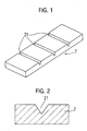
- Fig. 1 is a perspective view for illustrating a strip-shaped weight in a wheel balance weight of Example No. 1 according to the present invention;
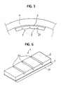
- Fig. 2 is a drawing for illustrating a cross section of the weight which is provided with a groove in the wheel balance weight of Example No. 1;
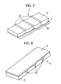
- Fig. 3 is a perspective view for illustrating the curved weight in the wheel balance weight of Example No. 1;
- Fig. 4 is a perspective view for illustrating the completed wheel balance weight of Example No. 1;
- Fig. 5 is a schematic drawing for illustrating the wheel balance weight of Example No. 1 which is installed to a rim in a wheel;
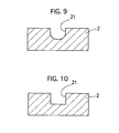
- Fig. 6 is a perspective view for illustrating a completed wheel balance weight of Example No. 2 according to the present invention;
- Fig. 7 is a perspective view for illustrating a completed wheel balance weight of Example No. 3 according to the present invention;
- Fig. 8 is a perspective view for illustrating a completed wheel balance weight of Example No. 4 according to the present invention;
- Fig. 9 is a drawing for illustrating a cross section of a weight which is provided with a letter "U"-shaped groove;
- Fig. 10 is a drawing for illustrating a cross section of a weight which is provided with a square-shaped dented groove; and
- Fig. 11 is a drawing for illustrating a cross section of a weight which is provided with a rust prevention film.
-
- Having generally described the present invention, a further understanding can be obtained by reference to the specific preferred embodiments which are provided herein for the purpose of illustration only and not intended to limit the scope of the appended claims.
- A wheel balance weight according to the present invention comprises a weight and installation means. The weight is composed of at least one member selected from the group consisting of zinc and a zinc-based alloy, is formed as a substantially strip shape having a substantially uniform thickness, and has opposite surfaces and at least a groove. The groove is formed in at least one of the opposite surfaces of the weight, and crosses in the width-wise direction of the weight. The installation means is adapted for installing the weight to a rim in a wheel. In the present wheel balance weight, the weight is composed of zinc or a zinc-based alloy which puts a less load onto environment. Therefore, even when the present wheel balance weight is abolished, the surrounding environments are inhibited from being polluted. Moreover, zinc or a zinc-based alloy exhibits a relatively low temperature so that it can be readily processed. Hence, it is possible to manufacture the present wheel balance weight at reduced costs and install it to wheels with ease.
- In the present wheel balance weight, zinc or a zinc-based alloy constitutes the weight. Zinc herein refers to pure zinc. The zinc-based alloy herein refers to alloys in which zinc makes a major component substantially. Specifically, the zinc-based alloy refers to zinc alloys whose zinc content is 39.5% by weight or more when the entirety is taken as 100% by weight. The zinc content can further preferably be 45% by weight or more, furthermore preferably be 50% by weight or more, moreover preferably be 90% by weight or more.
- Further, the weight can preferably be composed of a zinc-based alloy which comprises tin in an amount of less than 50% by weight, copper in an amount of less than 5% by weight, aluminum in an amount of less than 5% by weight, and the balance of zinc and inevitable impurities. The content of tin can further preferably be from 0 to 50% by weight, furthermore preferably be from 0 to 0.01% by weight. The content of copper can further preferably be from 0 to 5% by weight, furthermore preferably be from 0 to 1% by weight. The content of aluminum can further preferably be from 0 to 4.5% by weight, furthermore preferably be from 3.5 to 4.5% by weight. The content of inevitable impurities can be less than 1.5% by weight, further preferably be less than 0.5% by weight. When the weight is composed of the zinc-based alloy including these components, it is possible to secure processability which is required for the weight of the present wheel balance weight.
- Furthermore, when the weight is composed of zinc or the zinc-based alloy, the weight exhibits corrosion resistance of itself by the formation of passive films or the sacrificial rust prevention action. The passive films are composed of dense oxide films. Thus, the weight is inhibited from corroding. Accordingly, the weight is hardly suffered from the mass variation or damages which result from the corrosion. As a result, the longevity of the present wheel balance weight can be extended.
- Moreover, the weight has at least a groove, which is formed in at least one the opposite surfaces of the weight and which crosses in the width-wise direction. Since the weight has the groove, the thickness of the weight is reduced partially at the portion in which the groove is formed. In other words, the weight exhibits a lowered rigidity at the portion in which the groove is formed than at the other portions which are free from the groove or which have a larger thickness. Accordingly, when the present wheel balance weight is curved along a curved inner peripheral surface of a rim in a wheel in order to install the present wheel balance weight to the wheel, the weight can be bent at the portion in which the groove is formed. Thus, a curved shape is formed which goes along the inner peripheral surface of the rim in the wheel. Consequently, when the present wheel balance weight is installed to the wheel, it is possible to carry out the installation by curving the weight with a less force.
- Regarding the surface of the weight in which the groove is formed, it is not limited in particular. Namely, the groove can be formed in the opposite top surface of the weight, or can be formed in the opposite bottom surface thereof. In addition, the groove can be formed in both of the opposite top and bottom surfaces. Note that the opposite top surface of the weight herein means one of the opposite surfaces of the weight which faces radially inwardly the axial center of the wheel when the present wheel balance weight is installed to the wheel, and the opposite bottom surface of the weight herein means the other one of the opposite surfaces of the weight which faces the wheel radially outwardly, or which contacts with the inner peripheral surface of the rim in the wheel, when the present wheel balance weight is installed to the wheel.
- However, the groove can preferably be formed in the opposite bottom surface of the weight. When the groove is formed in the opposite bottom surface of the weight, it is possible to readily curve the weight along the inner peripheral surface of the rim in the wheel in installing the present wheel balance weight to the wheel. In particular, when the weight is curved, it is compressed on the opposite top surface side, and is extended on the opposite bottom surface side. Since the groove is formed in the opposite bottom surface of the weight, the width of the groove is widened when the weight is curved. When the width of the groove is widened, the length of the weight is prolonged on the opposite bottom-surface side of the weight. This phenomenon implies that the weight is not adversely affected by the ductility of zinc or the zinc-based alloy which makes the weight, and that the weight can be curved with a reduced force as well.
- Further, when the groove is formed in the opposite bottom surface of the weight, it is possible to make the opposite top surface of the wheel smooth or free from irregularities. Thus, it is possible not only to upgrade the appearance of the present wheel balance weight, but also to effect an advantage in that finger tips of operators are inhibited from being hurt by such irregularities during the installation of the present wheel balance weight to wheels.
- The weight is formed substantially as a strip shape having a substantially uniform thickness. The thickness of the weight herein refers to the thickness of the portions of the weight which are free from the groove. Here, the thickness of the weight is not limited in particular. Namely, the thickness can be a thickness which gives a desired mass to the weight. When the thickness of the weight is substantially uniform, it is possible to adjust the mass of the weight with ease. For example, when the dimensions of the weight are adjusted in the width-wise and longitudinal directions, it is possible to give a desired mass to the weight.
- Moreover, when the thickness of the weight is substantially uniform, the present wheel balance weight is installed to wheels with improved installation property. Namely, since the present wheel balance weight hardly requires excessive installation spaces in the thickness-wise direction when it is installed to wheels, it can be installed to a variety of wheels. Specifically, along with the recent trend of developing high-performance vehicle, the performance of the brake system has been improved as the power output is improved. As one of the improvements on the brake system performance, it has been intended to diametrically enlarge brakes. The diametric enlargement of brakes results in the decrement of the space between the inner peripheral surface of wheels and the outer peripheral surface of brakes (i.e., the installation space for wheel balance weights) within wheels. However, since the weight of the present wheel balance weight has a substantially uniform thickness, it is possible to install the present wheel balance weight without being interfered by brakes even when it is disposed at radially outwardly with respect to brakes.
- In addition, the installation means is not limited in particular as far as it can install the weight to a rim in a wheel. For example, the installation means can be the same means as a variety of installation means which have been used to install conventional wheel balance weights. Specifically, it is possible to name a clip which hooks the weight at peripheral ends of a rim in a wheel, and a double-sided tape which bonds the weight with a rim in a wheel.
- However, the installation means can preferably be a double-sided tape which has opposite adhesive surfaces, which are disposed back to back with each other. One of the adhesive surfaces is to be bonded onto the weight. The other one of the adhesive surfaces is to be bonded onto a rim in a wheel. When the installation means is such a double-sided tape, it is possible to install the present wheel balance weight to an inner peripheral surface of a rim in a wheel so that the appearance of the wheel is not impaired. Moreover, since such a less expensive double-sided tape is used as the installation means, it is possible to reduce the material costs of the present wheel balance weight. In addition, such a double-sided tape enables the present wheel balance weight to produce advantage in that no special devices are needed when the present wheel balance weight is installed to wheels.
- The cross sectional shape of the groove is not limited in particular, either. For example, the cross sectional shape of the groove can be shapes which enable the weight to curve along an inner peripheral surface of a rim in a wheel when the present wheel balance is installed to the wheel. Note that the cross sectional shape of the groove refers to the cross sectional shape in the perpendicular direction with resect to the extending direction of the groove. As for the cross sectional shape of the groove, it is possible to name such shapes as a substantially letter "V" shape (see Fig. 2), a substantially letter "U" shape (see Fig. 9), and a squarely dented shape (see Fig. 10). The cross sectional shape of the groove can further preferably be such that the width at the opening is greater than the width at the bottom.
- The weight can preferably be provided with a rust prevention film on the opposite top and bottom surfaces at least. When the weight is provided with a rust prevention film, the weight is inhibited from rusting. Moreover, when the weight is provided with a rust prevention film, the weight is inhibited from degrading the appearance. The appearance degradation is caused by the white rust which is generated when the weight being composed of zinc or the zinc-based alloy is oxidized. The rust prevention film is not limited in particular. However, the rust prevention film can preferably be an
acrylic resin film 5 as illustrated in Fig. 11, because such anacrylic resin film 5 can upgrade the appearance of the weight. In addition, theacrylic resin film 5 can further preferably be a metallic color film. - The weight can preferably be curved so as to go along an inner peripheral surface of a rim in a wheel. "The weight is curved so as to go along an inner peripheral surface of rim in a wheel" herein designates that the weight is curved at portions in which no groove is formed. When the weight of the present wheel balance weight is curved so as to go along an inner peripheral surface of a rim in a wheel, it is possible to install the present wheel balance weight to the inner peripheral surface with ease.
- Moreover, it is preferable to give an identification mark to the opposite top surface of the weight of the present wheel balance weight. For example, when the opposite top surface is marked with a mass of the weight, it is possible to readily identify and select a weight which has a desired mass. It is not limited, either, in terms of the way to give the identification mark to the opposite top surface of the weight.
- A process for manufacturing a wheel balance weight according to the present invention comprises a weight forming step and a double-sided tape applying step. In the weight forming step, a weight is formed. The resulting weight is composed of at least one member selected from the group consisting of zinc and a zinc-based alloy, is formed as a substantially strip shape having a substantially uniform thickness, and has opposite surfaces and at least a groove. The groove is formed in at least one of the opposite surfaces of the weight, and crosses in the width-wise direction of the weight. In the double-sided tape applying step, a double-sided tape, having opposite adhesive surfaces, is applied to the weight so as to adhere one of the opposite adhesive surfaces onto one of the opposite surfaces of the weight.
- In accordance with the present manufacturing, it is possible to manufacture the present wheel balance weight which comprises the weight being composed of zinc or the zinc-based alloy. Specifically, zinc or the zinc-based alloy puts a less load onto environment, and can be readily processed. Therefore, in accordance with the present manufacturing process, it is possible to manufacture the present wheel balance weight, which puts a less load onto environment, with ease.
- In the present manufacturing process, the weight forming step and the double-sided tape applying step are not limited in particular. As for the weight forming step and the double-sided tape applying step, it is possible to use means which have been used in manufacturing conventional wheel balance weights. Except for zinc or the zinc-based alloy making the weight, materials used in the present manufacturing process are not limited, either.
- For example, the weight forming step can preferably be a step of manufacturing the weight by casting zinc or the zinc-based alloy. Specifically, when the weight is formed by casting, it is possible to form the weight having a desired shape with ease. Moreover, since the weight is composed of the zinc-based alloy, it is possible to manufacture the weight by pouring a molten metal, in which raw metallic materials are solved, into a mold having cavities with a desired shape. Thus, it is possible to readily manufacture the weight having a desired shape.
- Moreover, the weight forming step can preferably be a step of forming the weight by pressing a plate-shaped member being composed of zinc or the zinc-based member. Since the weight is formed by pressing, the formed weight is improved in terms of the dimensional accuracy. As a result, it is possible to readily cancel the imbalance in wheels with the present wheel balance weight. Specifically, when the dimensional accuracy is upgraded, it is easy to find the center of gravity in the present wheel balance weight. Accordingly, it is possible to install the present wheel balance to wheels with enhanced installation accuracy. In addition, when the entire weight is subjected to pressing forming, the weight is compressed to enlarge the density. When the density is enlarged, it is possible to reduce the size of the weight.
- Here, the press forming in the weight forming step is not limited in particular as far as it is a method in which the weight can be formed by compressing a plate-shaped or wire-shaped member. For example, it is possible to name such means as cold forging, punching, cutting and stamping.
- The way to form the groove in the weight is not limited in particular, either. For instance, it is possible to name the following methods: in the casting, a mold can be provided with a protrusion which has been formed in advance to correspond to the groove, and the weight having the groove can be cast with the mold; and the groove can be formed by pressing a plate-shaped zinc or zinc-based alloy plate to dent it partially.
- In the double-sided tape applying step, one of the opposite adhesive surfaces of a double-sided tape can preferably be bonded onto one of the opposite surfaces of the weight. When one of the opposite adhesive surfaces of a double-sided tape is bonded onto one of the opposite surfaces of the weight, it is possible to readily manufacture the present wheel balance whose weight is assembled with a wheel by using the double-sided tape.
- Further, the present manufacturing process can preferably further comprise a film forming step, in which a rust prevention film is formed on the opposite surfaces at least, before carrying out the double-sided tape applying step. Thus, it is possible to manufacture the present wheel balance weight which is provided with a rust prevention film.
- Furthermore, the present manufacturing step can preferably further comprise a pre-treating step, in which the opposite surfaces of the weight cleansed, before carrying out the rust prevention film forming step. When the pre-treating step is carried out, it is possible to inhibit the resulting rust prevention coating from coming off which is often caused by dirt.
- Moreover, the present manufacturing process can preferably further comprises a step of giving an identification mark to the opposite top surface of the weight. The way to give an identification mark to the opposite top surface of the weight is not limited in particular, either.
- In addition, the present manufacturing step can preferably further comprise a weight cutting step in which the weight is cut to a predetermined length. When the weight is cut to a predetermined length, it is possible to give a desired mass to the weight.
- The weight cutting step can be carried out at any time as far as it is carried out after the weight forming step. However, the cutting step can further preferably be carried out after carrying out a groove forming step. When the weight cutting step is carried out after a groove forming step, it is possible to cut the weight, which is composed of zinc or the zinc-based alloy, with ease. Specifically, it is possible to cut the weight at the groove whose thickness is thinner than the other portions.
- Except for the above-described specific arrangements, the arrangements of the present manufacturing process are same as those of the present wheel balance weight. Therefore, the same specific arrangements will not be described herein in detail.
- The present invention will be hereinafter described in detail with reference to specific examples.
- In Example No. 1, a wheel balance weight as illustrated in Figs. 1 through 4 was manufactured. The manufacturing method of the wheel balance weight of Example No. 1 will be hereinafter described with reference to Figs. 1 through 4.
- First of all, metallic materials, such as metallic zinc, metallic tin, metallic copper and metallic aluminum, were weighed by a predetermined amount, respectively. Then, the metallic materials were charged into a crucible, and were heated. Thus, the metallic materials were melted to prepare a molten alloy. According to an weight analysis, the molten alloy contained zinc in an amount of 95% by weight, tin in an amount of 0.01% by weight, copper in an amount of 1% by weight, aluminum in an amount of 3.84% by weight, and the inevitable impurities in an amount of less than 0.15% by weight.
- Subsequently, the molten alloy was poured into a mold to manufacture a strip-shaped
weight 2. Note that a plurality ofgrooves 21 were formed in one of the opposite surfaces of theweight 2. Thegrooves 21 crossed in the width-wise direction of theweight 2. Thegrooves 21 formed in theweight 2 had a letter "V"-shaped cross section when they were cut in the longitudinal direction of the weight 2 (or viewed in the direction perpendicular to the longitudinal direction of the weight 2). - Thereafter, the
weight 2 was curved. For example, theweight 2 was curbed by such means as pressing and rolling. Theweight 2 was curved with a die so that it substantially conformed to a curved shape of an inner peripheral surface of a rim in a wheel when it was installed to the wheel. In this instance, theweight 2 was curved so that the opposite surface with thegrooves 21 formed faced inwardly in the radial direction of the wheel. Additionally, the other curving method was tried in which a curved portion had been provided in a mold in advance and a weight was formed with the mold. By both of the die, which curved the portions disposed between thegrooves 21 independently, and the mold, which curved the resulting weight entirely, it was possible to manufacture thecurved weight 2. - One of the opposite adhesive surfaces of a double-
sided tape 2 was adhered onto the other one of the opposite surfaces of thecurved weight 2 in which nogroove 21 was formed, or onto the opposite bottom surface of thecurved weight 2 which was to face a rim in a wheel radially outwardly. Note that theweight 2 was inhibited from adhering to places other than a wheel when it was handled, because the other one of the opposite adhesive surfaces of the double-sided tape 3 was covered with aseparator paper 31. - In accordance with the above-described steps, the
wheel balance weight 1 of Example No. 1 was manufactured. - The
wheel balance weight 1 of Example No. 1 was actually installed to a wheel by the following procedure. Here, Fig. 5 illustrates how thewheel balance weight 1 was installed to an inner peripheral surface of a rim in awheel 4. - First of all, the
separator paper 31 was removed from thewheel balance weight 1 of Example No. 1 to expose the other opposite adhesive surface of the double-sided tape 3. Subsequently, the exposed opposite adhesive surface was bonded to a predetermined position in an inner peripheral surface of a rim in thewheel 4 to install thewheel balance weight 1 to thewheel 4. In this instance, it was possible to snugly fit the contacting portions of theweight 2 to the curved shape of thewheel 4 by pressing theweight 2 onto the rim in thewheel 4. - In the
wheel balance weight 1 of Example No. 1, theweight 2 was curved more than the curvature of the inner peripheral surface of the rim in thewheel 4. Accordingly, when thewheel balance weight 1 was installed to thewheel 4, thecurved weight 2 was pressed to snugly fit to the curved inner peripheral surface of the rim in thewheel 4. In this instance, the letter "V"-shapedgrooves 21, which were formed in the opposite top surface of theweight 2, were contracted so that theweight 2 was fitted snugly to thewheel 4. - In Example No. 2, a
wheel balance weight 1 as illustrated in Fig. 6 was manufactured. Thewheel balance weight 1 is provided with a plate-shapedweight 2 in whichgrooves 21 having a letter "U"-shaped cross section were formed in one of the opposite surfaces. - In the
wheel balance weight 1 of Example No. 2, theweight 2 was manufactured by press working. - Specifically, a zinc alloy plate which had the same alloy composition as that of the
weight 2 of thewheel balance weight 1 of Example No. 1 was first cut to a strip shape. Then, the strip-shaped zinc alloy plate was pressed by a punch which had a predetermined shape to manufacture theweight 2 which was provided with thegrooves 21 in one of the opposite surfaces of the strip-shaped zinc alloy plate. Thegrooves 21 herein had a letter "U"-shaped cross section, and crossed in the width-wise direction of the strip-shapedweight 2. - Subsequently, one of the opposite adhesive surfaces of a double-
sided tape 2 was adhered onto the other one of the opposite surfaces of theweight 2 in which nogroove 21 was formed. - In accordance with the above-described steps, the
wheel balance weight 1 of Example No. 2 was manufactured. Fig. 6 illustrates the resultingwheel balance weight 1 of Example No. 2. - The
wheel balance weight 1 of Example No. 2 could be installed to a wheel in the same manner as thewheel balance weight 1 of Example No. 1. - A
wheel balance weight 1 of Example No. 3 is a modified version of thewheel balance weight 1 of Example No. 2. Except that thegrooves 21 had a letter "V"-shaped cross section, and that the portions of theweight 2 disposed between therespective grooves 21 were curved independently, thewheel balance weight 1 of Example No. 3 was the same as thewheel balance weight 1 of Example No. 2. - Specifically, a zinc alloy plate was cut to a strip shape in the same manner as Example No. 2. Then, a punch having a predetermined shape was pressed onto one of the opposite surfaces of the strip-shaped zinc alloy plate to form the
grooves 21 which crossed in the width-wise direction of theweight 2 and which had a letter "V"-shaped cross section. Thereafter, the portions of the strip-shaped zinc plate disposed between therespective grooves 21 were curved independently by press forming. Finally, the strip-shaped zinc plate was cut to a predetermined length to manufacture theweight 2. - Subsequently, one of the opposite adhesive surfaces of a double-
sided tape 2 was adhered onto the other one of the opposite surfaces of theweight 2 in which nogroove 21 was formed. - In accordance with the above-described steps, the
wheel balance weight 1 of Example No. 3 was manufactured. Fig. 7 illustrates the resultingwheel balance weight 1 of Example No. 3. - The
wheel balance weight 1 of Example No. 3 could be installed to a wheel in the same manner as thewheel balance weight 1 of Example No. 1. - Except that the
grooves 21 are formed in the opposite bottom surface of theweight 2, thewheel balance weight 1 of Example No. 4 was the same as thewheel balance weight 1 of Example No. 3. - Specifically, a zinc alloy plate was cut to a strip shape in the same manner as Example No. 3. Then, a punch having a predetermined shape was pressed onto one of the opposite surfaces of the strip-shaped zinc alloy plate to form the
grooves 21 which crossed in the width-wise direction of theweight 2 and which had a letter "V"-shaped cross section. Thereafter, the portions of the strip-shaped zinc plate disposed between therespective grooves 21 were curved independently by press forming. Finally, the strip-shaped zinc plate was cut to a predetermined length to manufacture theweight 2. - In Example No. 4, note that the punch, which was pressed onto one of the opposite surfaces of the zinc alloy plate, was formed so that it had different shapes at the central portion than at the opposite ends in the leading end surface. Specifically, the resulting
grooves 21 had a larger width at the central portion than at the opposite ends. Moreover, thegrooves 21 were formed so that the width varied from wide to narrow in the width-wise direction outwardly from the central portion to the opposite ends. - In the thus manufactured
weight 2 which was provided with thegrooves 21 formed by the punch, there arose no burrs, flashes, and the like, on the width-wise opposite end surfaces. Specifically, the deformation magnitude of the texture at the central portion in the zinc alloy plate differed from the deformation magnitudes of the textures at the opposite ends therein. Accordingly, when the texture was moved by a plastic deformation from the central portion to the opposite ends, the textures at the opposite ends could absorb the texture, which was moved from the central portion. As a result, it was possible to inhibit the burrs, flashes, and so forth, which would have protruded in the width-wise direction, from taking place. - Subsequently, one of the opposite adhesive surfaces of a double-
sided tape 2 was adhered onto one of the opposite surfaces of theweight 2 in which thegrooves 21 were formed, or onto the opposite bottom surface of theweight 2 which was to face a rim in a wheel radially outwardly. - In accordance with the above-described steps, the
wheel balance weight 1 of Example No. 4 was manufactured. Fig. 8 illustrates the resultingwheel balance weight 1 of Example No. 4. - In the same manner as the
wheel balance weight 1 of Example Nos. 1 through 3, it was possible to install thewheel balance weight 1 of Example No. 4 by pressing the other one of the opposite adhesive surfaces of the double-sided tape 2 onto a predetermined position in an inner peripheral surface of a rim in a wheel. Note that, prior to the installation of thewheel balance weight 1 of Example No. 4 to a wheel, thewheel balance weight 1 was cut to adjust the mass of thewheel balance weight 1 to a desired mass. Specifically, thewheel balance weight 1 was cut by repeatedly bending theweight 2 back and forth at one of thegrooves 21 until theweight 2 broke at thegroove 21. - When the
wheel balance weight 1 of Example No. 4 was pressed onto an inner peripheral surface of a rim in a wheel to install it to the wheel, theweight 2 was subjected to a stress, which expanded theweight 2 in the longitudinal direction, on the opposite bottom surface side, and another stress, which compressed theweight 2 in the longitudinal direction, on the opposite top surface side. - Due to the stresses, the width of the
grooves 21 was enlarged on the opposite bottom surface side. When the width of thegrooves 21 was thus enlarged at the opening, theweight 2 was curved so as to snugly fit to the curvature of the inner peripheral surface of the rim in the wheel. Simultaneously therewith, theweight 2 was adhered and fastened to the inner peripheral surface of the rim in the wheel. - In accordance with the above-described arrangements, it was possible to install the
wheel balance weight 1 of Example No. 4 to the rim in the wheel with ease. - Having now fully described the present invention, it will be apparent to one of ordinary skill in the art that many changes and modifications can be made thereto without departing from the spirit or scope of the present invention as set forth herein including the appended claims.
- A wheel balance weight includes a weight and an installation member. The weight is composed of at least one member selected from the group consisting of zinc and a zinc-based alloy, is formed as a substantially strip shape having a substantially uniform thickness, and has opposite surfaces and at least a groove. The groove is formed in at least one of the opposite surfaces of the weight, and crosses in the width-wise direction of the weight. The installation member is adapted for installing the weight to a rim in a wheel. Since the weight is composed of zinc or a zinc-based alloy, environments are inhibited from being polluted when the wheel balance weight is abolished. Moreover, it is possible to manufacture the wheel balance weight at reduced costs and install it to wheels with ease.
Claims (13)
- A wheel balance weight, comprising:a weight being composed of at least one member selected from the group consisting of zinc and a zinc-based alloy, being formed as a substantially strip shape having a substantially uniform thickness, and having opposite surfaces and at least a groove, the groove being formed in at least one of the opposite surfaces of the weight and crossing in the width-wise direction thereof; andinstallation means for installing the weight to a rim in a wheel.
- The wheel balance weight according to claim 1, wherein said installation means is a double-sided tape having opposite adhesive surfaces, one of the opposite adhesive surfaces to be bonded onto the weight, the other one of the opposite adhesive surfaces to be bonded onto the rim in the wheel.
- The wheel balance weight according to claim 1, wherein said weight has a rust prevention film on the opposite surfaces at least.
- The wheel balance weight according to claim 1, wherein the zinc-based alloy comprises zinc in an amount of 39.5% by weight or more when the entirety is taken as 100% by weight.
- The wheel balance weight according to claim 1, wherein the zinc-based alloy comprises tin in an amount of less than 50% by weight, copper in an amount of less than 5% by weight, aluminum in an amount of less than 5% by weight, and the balance of zinc and inevitable impurities.
- The wheel balance weight according to claim 1, wherein the groove is formed in one of the opposite surfaces of said weight which faces a wheel radially outwardly when the wheel balance weight is installed to the wheel.
- The wheel balance weight according to claim 1, wherein the groove has such a cross sectional shape that the width at the opening is greater than the width at the bottom when being viewed in the direction perpendicular to the longitudinal direction of the weight.
- The wheel balance weight according to claim 1, wherein said weight is curved so as to go along an inner peripheral surface of a rim in a wheel.
- A process for manufacturing a wheel balance weight, comprising the steps of:forming a weight being composed of at least one member selected from the group consisting of zinc and a zinc-based alloy, being formed as a substantially strip shape having a substantially uniform thickness, and having opposite surfaces and at least a groove, the groove being formed in at least one of the opposite surfaces of the weight and crossing in the width-wise direction thereof; andapplying a double-sided tape, having opposite adhesive surfaces, to the weight so as to adhere one of the opposite adhesive surfaces onto one of the opposite surfaces of the weight.
- The process according to claim 9, wherein, in said weight forming step, the weight is manufactured by casting at least one member selected from the group consisting of zinc and a zinc-based alloy.
- The process according to claim 9, wherein, in said weight forming step, the weight is formed by pressing a plate-shaped member being composed of at least one member selected from the group consisting of zinc and a zinc-based alloy.
- The process according to claim 9, wherein, in said weight forming step, at least a groove is formed in at least one of the opposite surfaces of the weight to cross in the width-wise direction thereof.
- The process according to claim 9 further comprising a step of coating a rust prevention film on the surfaces at least before carrying out said double-sided tape applying step.
Applications Claiming Priority (2)
| Application Number | Priority Date | Filing Date | Title |
|---|---|---|---|
| JP2002115264 | 2002-04-17 | ||
| JP2002115264A JP3730933B2 (en) | 2002-04-17 | 2002-04-17 | Wheel balance weight and manufacturing method thereof |
Publications (2)
| Publication Number | Publication Date |
|---|---|
| EP1355084A1 true EP1355084A1 (en) | 2003-10-22 |
| EP1355084B1 EP1355084B1 (en) | 2010-03-17 |
Family
ID=28672650
Family Applications (1)
| Application Number | Title | Priority Date | Filing Date |
|---|---|---|---|
| EP03008924A Revoked EP1355084B1 (en) | 2002-04-17 | 2003-04-16 | Wheel balance weight and process for manufacturing the same |
Country Status (4)
| Country | Link |
|---|---|
| US (1) | US6874856B2 (en) |
| EP (1) | EP1355084B1 (en) |
| JP (1) | JP3730933B2 (en) |
| DE (1) | DE60331705D1 (en) |
Cited By (8)
| Publication number | Priority date | Publication date | Assignee | Title |
|---|---|---|---|---|
| WO2004007993A1 (en) * | 2002-07-15 | 2004-01-22 | Plombco Inc. | Zinc based material wheel balancing weight |
| WO2006092241A1 (en) * | 2005-02-28 | 2006-09-08 | Bbs Motorsport & Engineering Gmbh | Balance weight |
| EP1983216A1 (en) | 2007-04-19 | 2008-10-22 | Taiho Kogyo Co., Ltd. | Wheel balance weight |
| EP1967757A4 (en) * | 2005-12-28 | 2011-12-07 | Taiho Kogyo Co Ltd | WHEEL BALANCING MASS |
| EP2610523A1 (en) * | 2011-12-30 | 2013-07-03 | WEGMANN automotive GmbH & Co. KG | Balancing weight for automated robot handling |
| EP2642157A1 (en) * | 2012-03-23 | 2013-09-25 | WEGMANN automotive GmbH & Co. KG | Apparatus and method for transport of balancing weights |
| EP2894371A1 (en) | 2014-01-08 | 2015-07-15 | Wegmann Automotive GmbH & Co. KG | Manually operated balancing weight dispenser |
| EP2988017A1 (en) * | 2014-08-21 | 2016-02-24 | WEGMANN automotive GmbH & Co. KG | Split self-adhesive balancing weight for a vehicle wheel |
Families Citing this family (20)
| Publication number | Priority date | Publication date | Assignee | Title |
|---|---|---|---|---|
| USD770925S1 (en) * | 1920-10-06 | 2016-11-08 | Wegmann Automotive Gmbh & Co. Kg | Tire balancing weight |
| US7055914B1 (en) * | 2002-07-15 | 2006-06-06 | Hennessy Industries, Inc. | Vehicle wheel balance weights |
| FR2844322B1 (en) * | 2002-09-10 | 2006-02-10 | Fonderie De Gentilly | ZINC OR ZINC ALLOY BALANCING DEVICE FOR WHEEL, SET OF SUCH DEVICES, WHEEL EQUIPPED WITH SUCH A DEVICE AND METHOD OF MANUFACTURE |
| AT501373B1 (en) * | 2004-09-01 | 2007-02-15 | Banner Gmbh | balance weight |
| US20060273652A1 (en) * | 2005-05-11 | 2006-12-07 | Conceptual Plastic Creations, Llc | Balance weight |
| GB2441977B (en) * | 2006-06-13 | 2008-05-28 | Escape Fitness Ltd | An exercise device |
| US20090243370A1 (en) * | 2008-03-31 | 2009-10-01 | Hennessy Industries, Inc. | Wheel weight |
| JP2011021066A (en) * | 2009-07-13 | 2011-02-03 | Toho Kogyo Kk | Method for producing roll tape for balance weight |
| JP5431211B2 (en) | 2010-03-05 | 2014-03-05 | 東豊工業株式会社 | Sticky wheel balance weight and manufacturing method thereof |
| ES2527728T3 (en) * | 2011-06-27 | 2015-01-29 | Wegmann Automotive Gmbh & Co. Kg | Balancing weight with activatable adhesive medium |
| USD754012S1 (en) * | 2014-01-30 | 2016-04-19 | Wegmann Automotive Gmbh & Co. Kg | Tire balancers (weights) |
| USD770923S1 (en) * | 2014-10-06 | 2016-11-08 | Wegmann Automotive Gmbh & Co. Kg | Tire balancing weights |
| USD770926S1 (en) * | 2014-10-06 | 2016-11-08 | Wegmann Automotive Gmbh & Co. Kg | Tire balancing weight |
| USD770922S1 (en) * | 2014-10-06 | 2016-11-08 | Wegmann Automotive Gmbh & Co. Kg | Tire balancing weight |
| USD770924S1 (en) * | 2014-10-06 | 2016-11-08 | Wegmann Automotive Gmbh & Co. Kg | Tire balancing weight |
| EP3203110B1 (en) * | 2016-02-02 | 2018-09-26 | WEGMANN automotive GmbH & Co. KG | Self-adhesive balancing weight for a vehicle wheel |
| KR101714404B1 (en) * | 2016-10-14 | 2017-03-09 | 김낙현 | Balance weight for tire wheel |
| JP1593261S (en) * | 2016-12-27 | 2017-12-18 | ||
| KR102022220B1 (en) * | 2019-06-14 | 2019-11-04 | 소우섭 | Complex type attachable wheel balance weight and method of the weight |
| KR102026057B1 (en) * | 2019-08-19 | 2019-09-26 | 소우섭 | Complex type attachable wheel balance weight and method of the weight |
Citations (4)
| Publication number | Priority date | Publication date | Assignee | Title |
|---|---|---|---|---|
| WO1999055924A1 (en) | 1998-04-27 | 1999-11-04 | Itri Limited | Tin alloy wheel balancing weights |
| JP2001173723A (en) * | 1999-12-20 | 2001-06-26 | Hitachi Powdered Metals Co Ltd | Balance weight for wheel |
| EP1128176A2 (en) * | 2000-02-23 | 2001-08-29 | Schenck RoTec GmbH | Strand of mutually connected metallic balancing weights |
| DE10102321A1 (en) | 2000-07-18 | 2002-02-14 | Franken Ind Werke Ernst Stenz | Balancing weight, especially for compensating imbalance of vehicle wheels, consists of zinc or a zinc based alloy |
Family Cites Families (11)
| Publication number | Priority date | Publication date | Assignee | Title |
|---|---|---|---|---|
| US2029132A (en) * | 1932-12-13 | 1936-01-28 | Chrysler Corp | Wheel balance |
| US2122064A (en) * | 1934-08-01 | 1938-06-28 | James W Hume | Wheel balancer |
| US2459568A (en) * | 1944-04-10 | 1949-01-18 | Lyon George Albert | Method of making wheel balancing weights |
| US2640727A (en) * | 1950-02-01 | 1953-06-02 | Raymond A Kennedy | Balancing weight |
| US2950142A (en) * | 1955-07-22 | 1960-08-23 | Lyon George Albert | Wheel balancing weight assembly |
| US3273941A (en) * | 1964-10-28 | 1966-09-20 | Donald Gottwald | Resiliently mounted wheel balancing weights |
| US3960409A (en) * | 1974-11-25 | 1976-06-01 | Perfect Equipment Corporation | Wheel balancing weight |
| US4300803A (en) * | 1979-09-14 | 1981-11-17 | Plumbium Manufacturing Corporation | Adhesive vehicle wheel weight and method |
| US6364421B1 (en) * | 1998-12-09 | 2002-04-02 | Perfect Equipment Company Llc | Wheel balancing weights |
| US6413626B1 (en) * | 2000-06-08 | 2002-07-02 | 3M Innovative Properties Company | Wheel weight/tape article and a method of using |
| JP3890983B2 (en) * | 2002-01-10 | 2007-03-07 | 東豊工業株式会社 | Wheel balance weight and manufacturing method thereof |
-
2002
- 2002-04-17 JP JP2002115264A patent/JP3730933B2/en not_active Expired - Fee Related
-
2003
- 2003-03-25 US US10/395,060 patent/US6874856B2/en not_active Expired - Fee Related
- 2003-04-16 EP EP03008924A patent/EP1355084B1/en not_active Revoked
- 2003-04-16 DE DE60331705T patent/DE60331705D1/en not_active Expired - Lifetime
Patent Citations (4)
| Publication number | Priority date | Publication date | Assignee | Title |
|---|---|---|---|---|
| WO1999055924A1 (en) | 1998-04-27 | 1999-11-04 | Itri Limited | Tin alloy wheel balancing weights |
| JP2001173723A (en) * | 1999-12-20 | 2001-06-26 | Hitachi Powdered Metals Co Ltd | Balance weight for wheel |
| EP1128176A2 (en) * | 2000-02-23 | 2001-08-29 | Schenck RoTec GmbH | Strand of mutually connected metallic balancing weights |
| DE10102321A1 (en) | 2000-07-18 | 2002-02-14 | Franken Ind Werke Ernst Stenz | Balancing weight, especially for compensating imbalance of vehicle wheels, consists of zinc or a zinc based alloy |
Non-Patent Citations (1)
| Title |
|---|
| PATENT ABSTRACTS OF JAPAN vol. 2000, no. 23 10 February 2001 (2001-02-10) * |
Cited By (15)
| Publication number | Priority date | Publication date | Assignee | Title |
|---|---|---|---|---|
| WO2004007993A1 (en) * | 2002-07-15 | 2004-01-22 | Plombco Inc. | Zinc based material wheel balancing weight |
| WO2006092241A1 (en) * | 2005-02-28 | 2006-09-08 | Bbs Motorsport & Engineering Gmbh | Balance weight |
| EP1967757A4 (en) * | 2005-12-28 | 2011-12-07 | Taiho Kogyo Co Ltd | WHEEL BALANCING MASS |
| EP1983216A1 (en) | 2007-04-19 | 2008-10-22 | Taiho Kogyo Co., Ltd. | Wheel balance weight |
| EP2610523A1 (en) * | 2011-12-30 | 2013-07-03 | WEGMANN automotive GmbH & Co. KG | Balancing weight for automated robot handling |
| WO2013139648A1 (en) * | 2012-03-23 | 2013-09-26 | Wegmann Automotive Gmbh & Co. Kg | Apparatus and method for transport of balancing weights |
| EP2642157A1 (en) * | 2012-03-23 | 2013-09-25 | WEGMANN automotive GmbH & Co. KG | Apparatus and method for transport of balancing weights |
| CN104471282A (en) * | 2012-03-23 | 2015-03-25 | 威格曼汽车有限两合公司 | Apparatus and method for transport of balancing weights |
| CN104471282B (en) * | 2012-03-23 | 2016-05-04 | 威格曼汽车有限两合公司 | For the device and method of transportation balance restructuring part |
| US9840388B2 (en) | 2012-03-23 | 2017-12-12 | Wegmann Automotive Gmbh & Co. Kg | Apparatus and method for transport of balancing weights |
| US10569983B2 (en) | 2012-03-23 | 2020-02-25 | Wegmann Automotive Gmbh | Apparatus and method for transport of balancing weights |
| EP2894371A1 (en) | 2014-01-08 | 2015-07-15 | Wegmann Automotive GmbH & Co. KG | Manually operated balancing weight dispenser |
| WO2015104208A1 (en) | 2014-01-08 | 2015-07-16 | Wegmann Automotive Gmbh & Co. Kg | Manually operated balancing weight dispenser |
| EP2988017A1 (en) * | 2014-08-21 | 2016-02-24 | WEGMANN automotive GmbH & Co. KG | Split self-adhesive balancing weight for a vehicle wheel |
| WO2016026776A3 (en) * | 2014-08-21 | 2016-11-24 | Wegmann Automotive Gmbh & Co. Kg | Split self-adhesive balancing weight for a vehicle wheel |
Also Published As
| Publication number | Publication date |
|---|---|
| JP2003314618A (en) | 2003-11-06 |
| JP3730933B2 (en) | 2006-01-05 |
| DE60331705D1 (en) | 2010-04-29 |
| US20030197421A1 (en) | 2003-10-23 |
| US6874856B2 (en) | 2005-04-05 |
| EP1355084B1 (en) | 2010-03-17 |
Similar Documents
| Publication | Publication Date | Title |
|---|---|---|
| US6874856B2 (en) | Wheel balance weight and process for manufacturing the same | |
| EP1327795B1 (en) | Wheel balance weight and process for manufacturing the same | |
| EP0994274B1 (en) | Wheel balance weight | |
| EP1248014B1 (en) | Wheel balance weight | |
| US6260929B1 (en) | Wheel balance weight and a method of manufacturing the same | |
| US20110012419A1 (en) | Wheel balance weight | |
| WO1999064762A1 (en) | Disc brake backing plate and method of manufacturing same | |
| US20050104439A1 (en) | Wheel weight with body having recess and clip secured therein | |
| EP1983216B1 (en) | Wheel balance weight | |
| GB2063722A (en) | Method for manufacturing vehicle wheels and wheels obtained thereby | |
| JP3503007B2 (en) | Wheel balance weight and method of manufacturing the same | |
| JPH11257437A5 (en) | ||
| JP2004084714A (en) | Manufacturing method of wheel balance weight for two-wheel motorcycle, and wheel balance weight for two-wheel motorcycle | |
| JP3066654U (en) | Wheel balance weight | |
| JP2002372103A (en) | Wheel balance weight | |
| JP3245383B2 (en) | Balancing weight | |
| JP2001173723A (en) | Balance weight for wheel | |
| JP3909970B2 (en) | Wheel balancing weight and manufacturing method thereof | |
| JP3046046U (en) | Balance weight member | |
| JP2002168295A (en) | Balance weight | |
| EP0175846A2 (en) | A wheel balance weight | |
| JP2002061714A (en) | Wheel balance weight | |
| JP3066945U (en) | Wheel balance weight | |
| JP2007255470A (en) | Stuck type balance weight member | |
| EP1456556A1 (en) | Wear indicator for braking pads for a disc brake |
Legal Events
| Date | Code | Title | Description |
|---|---|---|---|
| PUAI | Public reference made under article 153(3) epc to a published international application that has entered the european phase |
Free format text: ORIGINAL CODE: 0009012 |
|
| AK | Designated contracting states |
Kind code of ref document: A1 Designated state(s): AT BE BG CH CY CZ DE DK EE ES FI FR GB GR HU IE IT LI LU MC NL PT RO SE SI SK TR |
|
| AX | Request for extension of the european patent |
Extension state: AL LT LV MK |
|
| 17P | Request for examination filed |
Effective date: 20030926 |
|
| 17Q | First examination report despatched |
Effective date: 20040203 |
|
| AKX | Designation fees paid |
Designated state(s): DE FR GB |
|
| 17Q | First examination report despatched |
Effective date: 20040203 |
|
| GRAP | Despatch of communication of intention to grant a patent |
Free format text: ORIGINAL CODE: EPIDOSNIGR1 |
|
| GRAS | Grant fee paid |
Free format text: ORIGINAL CODE: EPIDOSNIGR3 |
|
| GRAA | (expected) grant |
Free format text: ORIGINAL CODE: 0009210 |
|
| AK | Designated contracting states |
Kind code of ref document: B1 Designated state(s): DE FR GB |
|
| REG | Reference to a national code |
Ref country code: GB Ref legal event code: FG4D |
|
| REF | Corresponds to: |
Ref document number: 60331705 Country of ref document: DE Date of ref document: 20100429 Kind code of ref document: P |
|
| PLBI | Opposition filed |
Free format text: ORIGINAL CODE: 0009260 |
|
| PLAX | Notice of opposition and request to file observation + time limit sent |
Free format text: ORIGINAL CODE: EPIDOSNOBS2 |
|
| 26 | Opposition filed |
Opponent name: WEGMANN AUTOMOTIVE GMBH & CO. KG Effective date: 20101215 |
|
| PLBB | Reply of patent proprietor to notice(s) of opposition received |
Free format text: ORIGINAL CODE: EPIDOSNOBS3 |
|
| PLCK | Communication despatched that opposition was rejected |
Free format text: ORIGINAL CODE: EPIDOSNREJ1 |
|
| APBM | Appeal reference recorded |
Free format text: ORIGINAL CODE: EPIDOSNREFNO |
|
| APBP | Date of receipt of notice of appeal recorded |
Free format text: ORIGINAL CODE: EPIDOSNNOA2O |
|
| APAH | Appeal reference modified |
Free format text: ORIGINAL CODE: EPIDOSCREFNO |
|
| APBQ | Date of receipt of statement of grounds of appeal recorded |
Free format text: ORIGINAL CODE: EPIDOSNNOA3O |
|
| PLAB | Opposition data, opponent's data or that of the opponent's representative modified |
Free format text: ORIGINAL CODE: 0009299OPPO |
|
| R26 | Opposition filed (corrected) |
Opponent name: WEGMANN AUTOMOTIVE GMBH & CO. KG Effective date: 20101215 |
|
| PGFP | Annual fee paid to national office [announced via postgrant information from national office to epo] |
Ref country code: DE Payment date: 20130508 Year of fee payment: 11 Ref country code: GB Payment date: 20130410 Year of fee payment: 11 |
|
| PGFP | Annual fee paid to national office [announced via postgrant information from national office to epo] |
Ref country code: FR Payment date: 20130625 Year of fee payment: 11 |
|
| REG | Reference to a national code |
Ref country code: DE Ref legal event code: R103 Ref document number: 60331705 Country of ref document: DE Ref country code: DE Ref legal event code: R064 Ref document number: 60331705 Country of ref document: DE |
|
| APBU | Appeal procedure closed |
Free format text: ORIGINAL CODE: EPIDOSNNOA9O |
|
| RDAF | Communication despatched that patent is revoked |
Free format text: ORIGINAL CODE: EPIDOSNREV1 |
|
| RDAG | Patent revoked |
Free format text: ORIGINAL CODE: 0009271 |
|
| STAA | Information on the status of an ep patent application or granted ep patent |
Free format text: STATUS: PATENT REVOKED |
|
| 27W | Patent revoked |
Effective date: 20131119 |
|
| GBPR | Gb: patent revoked under art. 102 of the ep convention designating the uk as contracting state |
Effective date: 20131119 |
|
| REG | Reference to a national code |
Ref country code: DE Ref legal event code: R107 Ref document number: 60331705 Country of ref document: DE Effective date: 20140417 |