EP1355075B1 - Verbund-Bremsscheibe für eine Fahrzeug-Scheibenbremse - Google Patents
Verbund-Bremsscheibe für eine Fahrzeug-Scheibenbremse Download PDFInfo
- Publication number
- EP1355075B1 EP1355075B1 EP03004698A EP03004698A EP1355075B1 EP 1355075 B1 EP1355075 B1 EP 1355075B1 EP 03004698 A EP03004698 A EP 03004698A EP 03004698 A EP03004698 A EP 03004698A EP 1355075 B1 EP1355075 B1 EP 1355075B1
- Authority
- EP
- European Patent Office
- Prior art keywords
- brake
- projection
- brake disc
- wall
- disc
- Prior art date
- Legal status (The legal status is an assumption and is not a legal conclusion. Google has not performed a legal analysis and makes no representation as to the accuracy of the status listed.)
- Expired - Lifetime
Links
Images
Classifications
-
- F—MECHANICAL ENGINEERING; LIGHTING; HEATING; WEAPONS; BLASTING
- F16—ENGINEERING ELEMENTS AND UNITS; GENERAL MEASURES FOR PRODUCING AND MAINTAINING EFFECTIVE FUNCTIONING OF MACHINES OR INSTALLATIONS; THERMAL INSULATION IN GENERAL
- F16D—COUPLINGS FOR TRANSMITTING ROTATION; CLUTCHES; BRAKES
- F16D65/00—Parts or details
- F16D65/02—Braking members; Mounting thereof
- F16D65/12—Discs; Drums for disc brakes
- F16D65/123—Discs; Drums for disc brakes comprising an annular disc secured to a hub member; Discs characterised by means for mounting
-
- F—MECHANICAL ENGINEERING; LIGHTING; HEATING; WEAPONS; BLASTING
- F16—ENGINEERING ELEMENTS AND UNITS; GENERAL MEASURES FOR PRODUCING AND MAINTAINING EFFECTIVE FUNCTIONING OF MACHINES OR INSTALLATIONS; THERMAL INSULATION IN GENERAL
- F16D—COUPLINGS FOR TRANSMITTING ROTATION; CLUTCHES; BRAKES
- F16D65/00—Parts or details
- F16D65/02—Braking members; Mounting thereof
- F16D65/10—Drums for externally- or internally-engaging brakes
-
- F—MECHANICAL ENGINEERING; LIGHTING; HEATING; WEAPONS; BLASTING
- F16—ENGINEERING ELEMENTS AND UNITS; GENERAL MEASURES FOR PRODUCING AND MAINTAINING EFFECTIVE FUNCTIONING OF MACHINES OR INSTALLATIONS; THERMAL INSULATION IN GENERAL
- F16D—COUPLINGS FOR TRANSMITTING ROTATION; CLUTCHES; BRAKES
- F16D65/00—Parts or details
- F16D65/02—Braking members; Mounting thereof
- F16D2065/13—Parts or details of discs or drums
- F16D2065/1304—Structure
- F16D2065/1316—Structure radially segmented
-
- F—MECHANICAL ENGINEERING; LIGHTING; HEATING; WEAPONS; BLASTING
- F16—ENGINEERING ELEMENTS AND UNITS; GENERAL MEASURES FOR PRODUCING AND MAINTAINING EFFECTIVE FUNCTIONING OF MACHINES OR INSTALLATIONS; THERMAL INSULATION IN GENERAL
- F16D—COUPLINGS FOR TRANSMITTING ROTATION; CLUTCHES; BRAKES
- F16D65/00—Parts or details
- F16D65/02—Braking members; Mounting thereof
- F16D2065/13—Parts or details of discs or drums
- F16D2065/134—Connection
- F16D2065/1376—Connection inner circumference
-
- F—MECHANICAL ENGINEERING; LIGHTING; HEATING; WEAPONS; BLASTING
- F16—ENGINEERING ELEMENTS AND UNITS; GENERAL MEASURES FOR PRODUCING AND MAINTAINING EFFECTIVE FUNCTIONING OF MACHINES OR INSTALLATIONS; THERMAL INSULATION IN GENERAL
- F16D—COUPLINGS FOR TRANSMITTING ROTATION; CLUTCHES; BRAKES
- F16D65/00—Parts or details
- F16D65/02—Braking members; Mounting thereof
- F16D2065/13—Parts or details of discs or drums
- F16D2065/134—Connection
- F16D2065/1392—Connection elements
Definitions
- the invention relates to a composite brake disc for a vehicle disc brake with a brake disk pot on which a brake disc friction ring or a driver carrying the friction ring or rings away from the Friction ring level is attached via a suitable projection, to which the itself extending substantially parallel to the brake disc axis of rotation annular projection viewed in the radial direction preferably within the possibly slightly weakened in this attachment area Wall of the brake disc pot is and rivets or similar fasteners provided between the pot wall and the projection are.
- a suitable projection to which the itself extending substantially parallel to the brake disc axis of rotation annular projection viewed in the radial direction preferably within the possibly slightly weakened in this attachment area Wall of the brake disc pot is and rivets or similar fasteners provided between the pot wall and the projection are.
- Composite brake discs per se are at least in the printed version
- the technique known and drawn in different embodiments characterized by the advantage that the brake disc friction ring on the one hand, on which is known to the friction linings of the disc brake for Concern be brought, and the so-called brake disk pot on the other hand, with which the disc brake on a wheel or the like.
- the brake disc friction ring on the one hand on which is known to the friction linings of the disc brake for Concern be brought, and the so-called brake disk pot on the other hand, with which the disc brake on a wheel or the like.
- a Weight savings can be achieved, and on the other hand is thus an advantageous Decoupling between the friction ring and the brake disc hub possible.
- At least on mass-produced passenger cars due to the required deceleration from partially high speeds high Requirements are made on the brake disc, such have Composite brake discs not yet enforced.
- the joining area bw. the joint between the Projection and the brake disk pot as a press or shrink fit form, but increase additional, substantially in the radial direction (with respect to the brake disc axis of rotation) provided connecting elements, which are, for example, to rivets, but also to screws or The like can act, the security of this network.
- these fasteners may be arranged to perform the function of Do not disturb the projection inner wall as the contact surface of a drum brake.
- the fasteners as a whole are for this in the radial direction as far outside, i. from the brake disc rotation axis arranged away the brake pads of the drum brake when Actuating the same, i. when applied to the inner wall of the projection, can not come into contact with these fasteners.
- this can be a head part or the like.
- the connecting elements be sunk at least substantially in the wall of the projection, so For example, a rivet head or a screw head or the like, so that the Brake element or the brake lining of the drum brake to the projection wall can be created without this - if the brake disc and thus the brake drum rotates - in contact with the connecting elements get.
- the connecting element still has a certain residual wall thickness of the Projection is required, so can a headboard or the like.
- the fasteners mechanically removed after the connection has been made or be formed, that the rotation axis facing inner wall the projection in each case easily as a contact surface of a drum brake can act.
- the pot wall i. the wall or the Mantel of the brake disk hub in the so-called. Attachment area in which the Connection with the so-called. Projection of the friction ring or said Friction ring driver is made to be at least slightly weakened can, to create a certain elasticity, but this is no feature required for the function of the present invention.
- the so-called projection does not have to be over its entire axial length a closed circular ring or closed circular cylinder form, but can certainly at least partially in the circumferential direction juxtaposed and separated from each other Projections or tongues or the like., Which is why the projection in previous text was described as "substantially annular”. It should also be mentioned that the substantially annular projection in Although radial direction preferably viewed within the wall or the Jacket of the brake disk pot is, but alternatively also in the radial direction from the outside can rest against the pot wall.
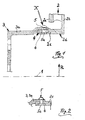
- Figure 1 shows a partial section of a composite brake disc according to the invention and Figure 2 in the form of a section X of Figure 1 shows a slight modification thereof.
- the so-called projection branches off from one of the friction rings of the brake disk, alternatively, however, the so-called projection can also be a component of a so-called driver, on which in turn the friction ring or a plurality of friction rings is fastened ,
- the reference numeral 1 is now the axis of rotation of the composite brake disc referred to, consisting of a friction ring 2 and a brake disc pot. 3 is composed.
- this joint 4 is characterized formed that from the inner periphery of the friction ring 2 with respect to the Rotary axis 1 circular cylindrical and thus to this parallel projection 2c protrudes, on which the brake disk cup 3 with a ring section his coat 3a rests.
- the joint 4, i. the connection between the jacket 3a of the brake disk hub 3 and the projection 2c the friction ring 2 formed as a press or shrink fit.
- all the exemplary embodiments are a ventilated friction ring 2 with a front annular disc 2a and a rear annular disc 2b, however, the present invention also in a massive (single) friction ring is implemented.
- the lead 2c from the rear (right) washer 2b to a sufficiently wide Friction surface 2 d to create on the inner wall of this projection 2 c, which then especially for a duo-servo parking brake, generally for one Drum brake, can be used.
- this depression 6, which in a further development as with respect to the axis of rotation 1 circumferential groove can be formed, a Range of increased elasticity, as well as a range of increased elasticity on Jacket 3a of the brake disk hub 3 is present near the joint 4, where the Jacket 3a has a reduced wall thickness. Because of these elasticities In particular, thermal stresses can be different Thermal expansion coefficients of the individual components of the composite brake disc result, at least partially compensated, as well as this principle already in the cited DE 100 32 972 A1 is described.
- the brake disk hub 3 in a high-strength light metal alloy (eg. AlSi7Mg), while the friction ring 2 with the projection 2c in a suitable casting material can be executed.
- a high-strength light metal alloy eg. AlSi7Mg
- the friction ring 2 with the projection 2c in a suitable casting material can be executed.
- the lead 2c is a component of a driver carrying the friction ring (s)
- a suitable steel in question It is still on it pointed out that a variety of details in particular constructive nature quite different from the embodiment shown be designed can, without leaving the content of the claims.
Description
Claims (4)
- Verbund-Bremsscheibe für eine Fahrzeug-Scheibenbremse mit einem Bremsscheibentopf (3), an dem ein Bremsscheiben-Reibring (2) oder ein den oder die Reibringe tragender Mitnehmer abseits der Reibring-Ebene über einen geeigneten Vorsprung (2c) befestigt ist, wozu der sich parallel zur Bremsscheiben-Drehachse (1) erstreckende im wesentliche ringförmige Vorsprung (2c) in Radialrichtung (R) betrachtet bevorzugt innerhalb der Wand (Mantel 3a) des Bremsscheibentopfes liegt und Nieten oder ähnliche Verbindungselemente (5) zwischen der Topfwand (Mantel 3a) und dem Vorsprung (2c) vorgesehen sind,
dadurch gekennzeichnet, dass die Verbindungselemente (5) in Radialrichtung (R) derart weit außen liegen, dass die der Drehachse (1) zugewandte Innenwand (2d) des Vorsprungs (2c) als Anlauffläche einer Trommelbremse fungieren kann. - Verbund-Bremsscheibe nach Anspruch 1,
dadurch gekennzeichnet, dass ein Kopfteil (5a) oder dgl. der Verbindungselemente (5) zumindest im wesentlichen in der Wand des Vorsprungs (2c) versenkt ist. - Verbund-Bremsscheibe nach Anspruch 1 oder 2,
dadurch gekennzeichnet, dass ein Kopfteil (5a) oder dgl. der Verbindungselemente (5) nach Herstellen der Verbindung soweit mechanisch abgetragen oder umgeformt ist, dass die der Drehachse (1) zugewandte Innenwand (2d) des Vorsprungs (2c) als Anlauffläche einer Trommelbremse fungieren kann. - Verbund-Bremsscheibe nach einem der vorangegangenen Ansprüche,
dadurch gekennzeichnet, dass der Bremsscheibentopf (3) in einer höherfesten Leichtmetall-Legierung und der Reibring (2) mit Vorsprung (2c) in einem Gusswerkstoff oder der Mitnehmer mit Vorsprung (2c) in Stahl ausgeführt ist.
Applications Claiming Priority (2)
| Application Number | Priority Date | Filing Date | Title |
|---|---|---|---|
| DE10217616A DE10217616A1 (de) | 2002-04-19 | 2002-04-19 | Verbund-Bremsscheibe für eine Fahrzeug-Scheibenbremse |
| DE10217616 | 2002-04-19 |
Publications (3)
| Publication Number | Publication Date |
|---|---|
| EP1355075A2 EP1355075A2 (de) | 2003-10-22 |
| EP1355075A3 EP1355075A3 (de) | 2004-06-30 |
| EP1355075B1 true EP1355075B1 (de) | 2005-05-25 |
Family
ID=28458936
Family Applications (1)
| Application Number | Title | Priority Date | Filing Date |
|---|---|---|---|
| EP03004698A Expired - Lifetime EP1355075B1 (de) | 2002-04-19 | 2003-03-04 | Verbund-Bremsscheibe für eine Fahrzeug-Scheibenbremse |
Country Status (2)
| Country | Link |
|---|---|
| EP (1) | EP1355075B1 (de) |
| DE (2) | DE10217616A1 (de) |
Cited By (2)
| Publication number | Priority date | Publication date | Assignee | Title |
|---|---|---|---|---|
| DE202016102524U1 (de) | 2016-04-27 | 2016-06-23 | Fritz Winter Eisengiesserei Gmbh & Co. Kg | Bremsscheibe für ein Fahrzeug |
| DE102017207139A1 (de) | 2017-04-27 | 2018-10-31 | Robert Bosch Gmbh | Bremsscheibenanordnung für eine Scheibenbremse eines Kraftfahrzeugs, Verfahren |
Families Citing this family (11)
| Publication number | Priority date | Publication date | Assignee | Title |
|---|---|---|---|---|
| EP1941172A1 (de) * | 2005-10-28 | 2008-07-09 | Brembo Ceramic Brake Systems S.p.A | Feststellbremse |
| DE102007053576B4 (de) * | 2007-11-09 | 2017-08-03 | Dr. Ing. H.C. F. Porsche Aktiengesellschaft | Bremsvorrichtung |
| KR20100035258A (ko) * | 2008-09-26 | 2010-04-05 | 주식회사 데크 | 주차 브레이크용 드럼과 디스크 브레이크용 디스크 로터가 일체로 형성된 dih 구조의 브레이크 디스크 |
| DE102010037123B4 (de) * | 2010-08-23 | 2020-08-06 | Leiber Group Gmbh & Co. Kg Aluminium Umform- Und Bearbeitungstechnik | Bremsanlage mit einem Bremsscheibentopf, einer Trommel sowie mindestens einem Reibring als Bremsscheibe und Verfahren zu einer Herstellung |
| DE102013002300B3 (de) * | 2013-02-08 | 2014-07-17 | Audi Ag | Bremsscheibe für eine Scheibenbremse eines Kraftfahrzeugs |
| DE102015110104A1 (de) | 2015-06-24 | 2016-12-29 | Dr. Ing. H.C. F. Porsche Aktiengesellschaft | Bremsscheibenvorrichtung für ein Fahrzeug |
| US9982732B2 (en) | 2015-08-04 | 2018-05-29 | Gri Engineering & Development, Llc | Vehicle brake rotor and method of making same |
| DE102018212862A1 (de) | 2017-08-02 | 2019-02-07 | Robert Bosch Gmbh | Bremsscheibe und Verfahren zur Herstellung einer Bremsscheibe |
| DE102018009194A1 (de) | 2018-11-22 | 2020-05-28 | Zf Active Safety Gmbh | Bremsscheibe für eine Fahrzeugscheibenbremse |
| DE102019213756A1 (de) | 2019-01-11 | 2020-07-16 | Continental Teves Ag & Co. Ohg | Topfförmiger Verbundbremsrotor für Kraftfahrzeuge |
| GB2583525A (en) * | 2019-05-03 | 2020-11-04 | Eurac Ltd | Brake disks |
Family Cites Families (7)
| Publication number | Priority date | Publication date | Assignee | Title |
|---|---|---|---|---|
| US4854423A (en) * | 1988-07-26 | 1989-08-08 | Kelsey Hayes Company | Hydraulic disc brake drum-in-hat parking brake assembly |
| US5385216A (en) * | 1993-06-04 | 1995-01-31 | The Budd Company | Composite rear brake disc and drum |
| DE4419757A1 (de) * | 1994-06-06 | 1995-12-07 | Teves Gmbh Alfred | Bremsscheibe |
| DE19652464A1 (de) * | 1996-12-17 | 1998-06-18 | Bayerische Motoren Werke Ag | Zusammengesetzte Bremsscheibe |
| EP1128084A3 (de) * | 2000-02-23 | 2003-10-29 | Bayerische Motoren Werke Aktiengesellschaft | Verfahren zur Herstellung einer Bremsscheibe |
| DE10032972B4 (de) * | 2000-07-06 | 2004-04-15 | Bayerische Motoren Werke Ag | Verbund-Bremsscheibe für eine Fahrzeug-Scheibenbremse |
| DE10104039A1 (de) * | 2001-01-31 | 2002-08-01 | Bayerische Motoren Werke Ag | Gebaute Bremsscheibe, insbesondere für ein Kfz |
-
2002
- 2002-04-19 DE DE10217616A patent/DE10217616A1/de not_active Withdrawn
-
2003
- 2003-03-04 EP EP03004698A patent/EP1355075B1/de not_active Expired - Lifetime
- 2003-03-04 DE DE50300567T patent/DE50300567D1/de not_active Expired - Lifetime
Cited By (5)
| Publication number | Priority date | Publication date | Assignee | Title |
|---|---|---|---|---|
| DE202016102524U1 (de) | 2016-04-27 | 2016-06-23 | Fritz Winter Eisengiesserei Gmbh & Co. Kg | Bremsscheibe für ein Fahrzeug |
| DE102016107823A1 (de) | 2016-04-27 | 2017-11-02 | Fritz Winter Eisengiesserei Gmbh & Co. Kg | Bremsscheibe für ein Fahrzeug |
| WO2017186867A1 (de) | 2016-04-27 | 2017-11-02 | Fritz Winter Eisengiesserei Gmbh & Co. Kg | Bremsscheibe für ein fahrzeug |
| DE102017207139A1 (de) | 2017-04-27 | 2018-10-31 | Robert Bosch Gmbh | Bremsscheibenanordnung für eine Scheibenbremse eines Kraftfahrzeugs, Verfahren |
| WO2018197321A1 (de) | 2017-04-27 | 2018-11-01 | Robert Bosch Gmbh | Bremsscheibenanordnung für eine scheibenbremse eines kraftfahrzeugs, verfahren |
Also Published As
| Publication number | Publication date |
|---|---|
| DE50300567D1 (de) | 2005-06-30 |
| DE10217616A1 (de) | 2003-11-06 |
| EP1355075A3 (de) | 2004-06-30 |
| EP1355075A2 (de) | 2003-10-22 |
Similar Documents
| Publication | Publication Date | Title |
|---|---|---|
| DE19581383B4 (de) | Verfahren zur Montage einer verriegelbaren Kupplung für ein hydrodynamisches Getriebe, insbesondere für Kraftfahrzeuge, entsprechende verriegelbare Kupplung und hydrodynamisches Getriebe mit einer solchen verriegelbaren Kupplung | |
| EP3033540B1 (de) | Bremsscheibe für ein fahrzeug | |
| DE10032972B4 (de) | Verbund-Bremsscheibe für eine Fahrzeug-Scheibenbremse | |
| EP2553290B1 (de) | Bremsscheibe | |
| EP1355075B1 (de) | Verbund-Bremsscheibe für eine Fahrzeug-Scheibenbremse | |
| EP3212433B1 (de) | Fahrzeugrad mit einer verbindung zwischen einer radfelge und einer radscheibe und verfahren zu dessen herstellung | |
| DE102008044136A1 (de) | Radträger eines Kraftfahrzeuges | |
| EP1426644B1 (de) | Verbundbremsscheibe für eine Fahrzeug-Scheibenbremse | |
| DE102014017715A1 (de) | Pneumatisch oder elektromechanisch betätigte Scheibenbremse für Nutzfahrzeuge | |
| DE102009010747A1 (de) | Bremsscheibe für ein Fahrzeug sowie Verfahren zum Herstellen einer solchen | |
| DE102017116681B3 (de) | Bremsscheibe | |
| EP3394468B1 (de) | Bremsscheibe für ein fahrzeug | |
| EP3795853B1 (de) | Schienenrad umfassend eine bremsscheibe mit einem segmentierten reibring | |
| DE102016225155A1 (de) | Radlagereinheit und Radträger | |
| EP2507530B1 (de) | Radbaugruppe | |
| DE10254110B4 (de) | Bremsscheibe mit einem Reibring aus einem im wesentlichen nichtmetallischen Werkstoff | |
| DE102010004866A1 (de) | Halteanordnung einer Bremsscheibe an einer Radnabe eines Kraftwagens | |
| DE19858243B4 (de) | Bremsscheibe für Scheibenbremsen | |
| EP1335144B1 (de) | Bremsträgeranordnung | |
| DE102016107823A1 (de) | Bremsscheibe für ein Fahrzeug | |
| DE102019103801A1 (de) | Gebaute Bremsscheibe und Verfahren zur Herstellung einer solchen Bremsscheibe | |
| DE102008031709A1 (de) | Scheibenbremsanordnung für ein Fahrzeug, insbesondere für ein Nutzfahrzeug | |
| DE102021213374B4 (de) | Scheibenbremssystem mit einseitiger Druckbeaufschlagung | |
| EP1162384A2 (de) | Fahrzeug-Bremsscheibe, deren Reibring und Bremsscheibentopf aus unterschiedlichen Werkstoffen besteht | |
| DE19723036A1 (de) | Bremstrommel |
Legal Events
| Date | Code | Title | Description |
|---|---|---|---|
| PUAI | Public reference made under article 153(3) epc to a published international application that has entered the european phase |
Free format text: ORIGINAL CODE: 0009012 |
|
| AK | Designated contracting states |
Kind code of ref document: A2 Designated state(s): AT BE BG CH CY CZ DE DK EE ES FI FR GB GR HU IE IT LI LU MC NL PT RO SE SI SK TR |
|
| AX | Request for extension of the european patent |
Extension state: AL LT LV MK |
|
| PUAL | Search report despatched |
Free format text: ORIGINAL CODE: 0009013 |
|
| AK | Designated contracting states |
Kind code of ref document: A3 Designated state(s): AT BE BG CH CY CZ DE DK EE ES FI FR GB GR HU IE IT LI LU MC NL PT RO SE SI SK TR |
|
| AX | Request for extension of the european patent |
Extension state: AL LT LV MK |
|
| 17P | Request for examination filed |
Effective date: 20040714 |
|
| GRAP | Despatch of communication of intention to grant a patent |
Free format text: ORIGINAL CODE: EPIDOSNIGR1 |
|
| GRAS | Grant fee paid |
Free format text: ORIGINAL CODE: EPIDOSNIGR3 |
|
| AKX | Designation fees paid |
Designated state(s): DE FR GB IT |
|
| GRAA | (expected) grant |
Free format text: ORIGINAL CODE: 0009210 |
|
| AK | Designated contracting states |
Kind code of ref document: B1 Designated state(s): DE FR GB IT |
|
| REG | Reference to a national code |
Ref country code: GB Ref legal event code: FG4D Free format text: NOT ENGLISH |
|
| GBT | Gb: translation of ep patent filed (gb section 77(6)(a)/1977) |
Effective date: 20050525 |
|
| REG | Reference to a national code |
Ref country code: IE Ref legal event code: FG4D Free format text: LANGUAGE OF EP DOCUMENT: GERMAN |
|
| REF | Corresponds to: |
Ref document number: 50300567 Country of ref document: DE Date of ref document: 20050630 Kind code of ref document: P |
|
| ET | Fr: translation filed | ||
| PLBE | No opposition filed within time limit |
Free format text: ORIGINAL CODE: 0009261 |
|
| STAA | Information on the status of an ep patent application or granted ep patent |
Free format text: STATUS: NO OPPOSITION FILED WITHIN TIME LIMIT |
|
| 26N | No opposition filed |
Effective date: 20060228 |
|
| REG | Reference to a national code |
Ref country code: FR Ref legal event code: PLFP Year of fee payment: 14 |
|
| REG | Reference to a national code |
Ref country code: FR Ref legal event code: PLFP Year of fee payment: 15 |
|
| REG | Reference to a national code |
Ref country code: FR Ref legal event code: PLFP Year of fee payment: 16 |
|
| PGFP | Annual fee paid to national office [announced via postgrant information from national office to epo] |
Ref country code: GB Payment date: 20220324 Year of fee payment: 20 Ref country code: DE Payment date: 20220316 Year of fee payment: 20 |
|
| PGFP | Annual fee paid to national office [announced via postgrant information from national office to epo] |
Ref country code: FR Payment date: 20220323 Year of fee payment: 20 |
|
| PGFP | Annual fee paid to national office [announced via postgrant information from national office to epo] |
Ref country code: IT Payment date: 20220331 Year of fee payment: 20 |
|
| REG | Reference to a national code |
Ref country code: DE Ref legal event code: R071 Ref document number: 50300567 Country of ref document: DE |
|
| REG | Reference to a national code |
Ref country code: GB Ref legal event code: PE20 Expiry date: 20230303 |
|
| PG25 | Lapsed in a contracting state [announced via postgrant information from national office to epo] |
Ref country code: GB Free format text: LAPSE BECAUSE OF EXPIRATION OF PROTECTION Effective date: 20230303 |
|
| P01 | Opt-out of the competence of the unified patent court (upc) registered |
Effective date: 20230427 |