EP1355059A2 - Fuel pump - Google Patents
Fuel pump Download PDFInfo
- Publication number
- EP1355059A2 EP1355059A2 EP03009049A EP03009049A EP1355059A2 EP 1355059 A2 EP1355059 A2 EP 1355059A2 EP 03009049 A EP03009049 A EP 03009049A EP 03009049 A EP03009049 A EP 03009049A EP 1355059 A2 EP1355059 A2 EP 1355059A2
- Authority
- EP
- European Patent Office
- Prior art keywords
- fuel
- seal member
- plunger
- pressure
- cylinder
- Prior art date
- Legal status (The legal status is an assumption and is not a legal conclusion. Google has not performed a legal analysis and makes no representation as to the accuracy of the status listed.)
- Granted
Links
- 239000000446 fuel Substances 0.000 title claims abstract description 139
- 239000000463 material Substances 0.000 claims abstract description 12
- 238000005299 abrasion Methods 0.000 claims abstract description 8
- 239000002828 fuel tank Substances 0.000 claims description 9
- 238000002485 combustion reaction Methods 0.000 claims description 7
- 239000004809 Teflon Substances 0.000 claims description 6
- 229920006362 Teflon® Polymers 0.000 claims description 6
- 238000007789 sealing Methods 0.000 claims description 3
- 239000000314 lubricant Substances 0.000 description 30
- 238000002347 injection Methods 0.000 description 3
- 239000007924 injection Substances 0.000 description 3
- RTZKZFJDLAIYFH-UHFFFAOYSA-N Diethyl ether Chemical compound CCOCC RTZKZFJDLAIYFH-UHFFFAOYSA-N 0.000 description 2
- 230000002159 abnormal effect Effects 0.000 description 2
- 238000010276 construction Methods 0.000 description 2
- 239000010409 thin film Substances 0.000 description 2
- YCKRFDGAMUMZLT-UHFFFAOYSA-N Fluorine atom Chemical compound [F] YCKRFDGAMUMZLT-UHFFFAOYSA-N 0.000 description 1
- 239000011248 coating agent Substances 0.000 description 1
- 238000000576 coating method Methods 0.000 description 1
- 230000000694 effects Effects 0.000 description 1
- 238000005516 engineering process Methods 0.000 description 1
- 239000010408 film Substances 0.000 description 1
- 229910052731 fluorine Inorganic materials 0.000 description 1
- 239000011737 fluorine Substances 0.000 description 1
- 239000007788 liquid Substances 0.000 description 1
- 230000001050 lubricating effect Effects 0.000 description 1
- 238000005461 lubrication Methods 0.000 description 1
- 239000000203 mixture Substances 0.000 description 1
- 238000012986 modification Methods 0.000 description 1
- 230000004048 modification Effects 0.000 description 1
- 230000001737 promoting effect Effects 0.000 description 1
- 239000011347 resin Substances 0.000 description 1
- 229920005989 resin Polymers 0.000 description 1
Images



Classifications
-
- F—MECHANICAL ENGINEERING; LIGHTING; HEATING; WEAPONS; BLASTING
- F02—COMBUSTION ENGINES; HOT-GAS OR COMBUSTION-PRODUCT ENGINE PLANTS
- F02M—SUPPLYING COMBUSTION ENGINES IN GENERAL WITH COMBUSTIBLE MIXTURES OR CONSTITUENTS THEREOF
- F02M63/00—Other fuel-injection apparatus having pertinent characteristics not provided for in groups F02M39/00 - F02M57/00 or F02M67/00; Details, component parts, or accessories of fuel-injection apparatus, not provided for in, or of interest apart from, the apparatus of groups F02M39/00 - F02M61/00 or F02M67/00; Combination of fuel pump with other devices, e.g. lubricating oil pump
- F02M63/02—Fuel-injection apparatus having several injectors fed by a common pumping element, or having several pumping elements feeding a common injector; Fuel-injection apparatus having provisions for cutting-out pumps, pumping elements, or injectors; Fuel-injection apparatus having provisions for variably interconnecting pumping elements and injectors alternatively
- F02M63/0225—Fuel-injection apparatus having a common rail feeding several injectors ; Means for varying pressure in common rails; Pumps feeding common rails
-
- F—MECHANICAL ENGINEERING; LIGHTING; HEATING; WEAPONS; BLASTING
- F02—COMBUSTION ENGINES; HOT-GAS OR COMBUSTION-PRODUCT ENGINE PLANTS
- F02M—SUPPLYING COMBUSTION ENGINES IN GENERAL WITH COMBUSTIBLE MIXTURES OR CONSTITUENTS THEREOF
- F02M59/00—Pumps specially adapted for fuel-injection and not provided for in groups F02M39/00 -F02M57/00, e.g. rotary cylinder-block type of pumps
- F02M59/20—Varying fuel delivery in quantity or timing
- F02M59/36—Varying fuel delivery in quantity or timing by variably-timed valves controlling fuel passages to pumping elements or overflow passages
- F02M59/366—Valves being actuated electrically
-
- F—MECHANICAL ENGINEERING; LIGHTING; HEATING; WEAPONS; BLASTING
- F02—COMBUSTION ENGINES; HOT-GAS OR COMBUSTION-PRODUCT ENGINE PLANTS
- F02M—SUPPLYING COMBUSTION ENGINES IN GENERAL WITH COMBUSTIBLE MIXTURES OR CONSTITUENTS THEREOF
- F02M59/00—Pumps specially adapted for fuel-injection and not provided for in groups F02M39/00 -F02M57/00, e.g. rotary cylinder-block type of pumps
- F02M59/44—Details, components parts, or accessories not provided for in, or of interest apart from, the apparatus of groups F02M59/02 - F02M59/42; Pumps having transducers, e.g. to measure displacement of pump rack or piston
- F02M59/442—Details, components parts, or accessories not provided for in, or of interest apart from, the apparatus of groups F02M59/02 - F02M59/42; Pumps having transducers, e.g. to measure displacement of pump rack or piston means preventing fuel leakage around pump plunger, e.g. fluid barriers
-
- F—MECHANICAL ENGINEERING; LIGHTING; HEATING; WEAPONS; BLASTING
- F04—POSITIVE - DISPLACEMENT MACHINES FOR LIQUIDS; PUMPS FOR LIQUIDS OR ELASTIC FLUIDS
- F04B—POSITIVE-DISPLACEMENT MACHINES FOR LIQUIDS; PUMPS
- F04B53/00—Component parts, details or accessories not provided for in, or of interest apart from, groups F04B1/00 - F04B23/00 or F04B39/00 - F04B47/00
- F04B53/04—Draining
-
- F—MECHANICAL ENGINEERING; LIGHTING; HEATING; WEAPONS; BLASTING
- F04—POSITIVE - DISPLACEMENT MACHINES FOR LIQUIDS; PUMPS FOR LIQUIDS OR ELASTIC FLUIDS
- F04B—POSITIVE-DISPLACEMENT MACHINES FOR LIQUIDS; PUMPS
- F04B53/00—Component parts, details or accessories not provided for in, or of interest apart from, groups F04B1/00 - F04B23/00 or F04B39/00 - F04B47/00
- F04B53/16—Casings; Cylinders; Cylinder liners or heads; Fluid connections
- F04B53/162—Adaptations of cylinders
- F04B53/164—Stoffing boxes
Definitions
- the present Invention relates to a fuel pump that supplies pressurized fuel to an internal combustion engine and in particular, to a technology of improving a seal performance of the fuel pump with regard to lubricant and fuel therein.
- a pressure of the fuel supplied from a fuel tank to a fuel injector needs to be pressurized to a sufficiently high pressure (for example, 3-12 Mpa) by a fuel pump.
- a mechanical fuel pump connected to a camshaft is used along with the pump.
- This mechanical fuel pump in general, includes a pump-driving cam mounted to a camshaft for opening and closing an intake valve or an exhaust valve and pressurizes fuel therein by reciprocating a plunger in a cylinder by rotation of the camshaft.
- a Japanese Unexamined Patent Publication No. 8 - 68370 has disclosed the mechanical fuel pump where a seal member contacts an outer surface of a plunger with a lip portion thereof to prevent lubricant for sliding the plunger from mixing with the fuel.
- the fuel pump Since the above earlier fuel pump has one single seal member to prevent mixing the lubricant with the fuel, the fuel pump has the following problems when applied to an engine with a high engine output and a large exhaust amount.
- a plunger-stroke amount needs to increase corresponding to an increase of a fuel-flow amount required for the engine.
- a distance of a sliding movement of a plunger-outer surface to a seal member becomes longer and therefore, durability of the seal member needs to improve further.
- a flow of the lubricant and the fuel is mostly prevented by the seal member.
- a preciously small amount thereof is left as a thin liquid film between the plunger-outer surface and the seal member and when a plunger reciprocates, this preciously small amount thereof passes through the seal member.
- the plunger-stroke amount increases, a region where the lubricant directly contacts the fuel is enlarged, thereby promoting mixing the lubricant with the fuel.
- the lubricant mixed with the fuel bums and therefore, an exhaust gas emission deteriorates or the lubricant is diluted by the fuel mixed, thereby worsening a lubrication performance thereof.
- One aspect of the present invention in view of the foregoing problems, provides a fuel pump where even when a stroke length of a plunger in a fuel pump increases, durability of a seal member does not deteriorate and mixing lubricant with fuel is properly prevented.
- the present invention provides a fuel pump that pressurizes fuel and supplies a pressurized fuel to an internal combustion engine, comprising:
- Fig. 1 is a schematic structural view of a fuel supply apparatus in an internal combustion engine which a fuel pump according to the invention is applied to.
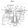
- Fig. 2 is a structural view of a high-pressure-fuel pump of a first embodiment according to the invention.
- Fig. 3 is a fragmentary view of explaining an operation of a first seal member and a second seal member in relation to lubricant and fuel movement in a clearance defined between an inner surface of a cylinder and an outer surface of a plunger.
- Fig. 4 is a structural view of a high-pressure-fuel pump of a second embodiment according to the invention.
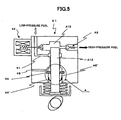
- Fig. 5 is a structural view of a high-pressure-fuel pump of a third embodiment according to the invention.
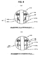
- Fig. 6 is an enlarged view of A-portion in Fig. 5 showing the first seal member for lubricant formed of a seal lip structure.
- Fig. 1 is a schematic structural view of a fuel supply apparatus in an internal combustion engine which a fuel pump according to the invention is applied to.
- Fig. 2 is a structural view of a high-pressure-fuel pump of a first embodiment according to the invention.
- the fuel supply apparatus comprises a fuel tank 2, a low-pressure-fuel pump unit 3, a high-pressure-fuel pump 4, an injector 5, and an engine control unit (ECU) 6.
- ECU engine control unit
- Low-pressure-fuel pump unit 3 and high-pressure fuel pump 4 are connected by a low-pressure-fuel passage 7, and high-pressure-fuel pump 4 and injector 5 are connected through a high-pressure-fuel passage 8.
- Low-pressure-pump unit 3 is disposed in fuel tank 2, including a feed pump 31, a fuel filter 32, and a low-pressure-pressure regulator 33.
- Feed pump 31 discharges fuel in fuel tank 2 and fuel filter 32 percolates the fuel discharged from feed pump 31.
- Low-pressure-pressure regulator 33 bypasses low-pressure-fuel passage 7 and adjusts a pressure of the fuel discharged from feed pump 31 to a certain pressure (low pressure).
- High-pressure-fuel pump 4 pressurizes the fuel adjusted by low-pressure-fuel pump unit 3 to a sufficiently high pressure for supply to injector 5, including, as shown in Fig. 1 and 2, a pump body 41, an electromagnetic control valve 42, and a discharge check valve 43.
- Pump body 41 is mounted to a cylinder head of the engine, including a cylinder 411, a cylindrical plunger 412 slidably inserted into cylinder 411, and a pressure chamber 413 that is defined by an inner wall surface forming an upper closed end of cylinder 411 and a crest surface of plunger 412.
- Plunger 412 is disposed forming a predetermined insert clearance between an outer surface 412a of plunger 412 and an inner surface 411a of cylinder 411 and a bottom end thereof is connected to a lifter 414.
- Lifter 414 is regularly forced against a camshaft 9 (for example, an intake valve-driving or an exhaust valve-driving camshaft) having a pump-driving cam 9a by a return spring 415, Rotation of camshaft 9 causes plunger 412 to reciprocate in the Arrow Y - Y' direction of Fig. 2 and to pressurize fuel introduced to pressure chamber 413.
- camshaft 9 for example, an intake valve-driving or an exhaust valve-driving camshaft
- Pressure chamber 413 is connected to a fuel supply passage 417 through one connection portion 416 and connected to a fuel discharge passage 419 through the other connection portion 418.
- Fuel supply passage 417 is connected to low-pressure-fuel passage 7 and fuel discharge passage 419 is connected to high-pressure-fuel passage 8.
- Connection passage 416 that connects pressure chamber 413 to fuel supply passage 417 is opened and closed by electromagnetic control valve 42.
- a valve body 422 changes from a valve closed position where valve body 422 is seated by spring force of a return spring 421 to a valve opened position to which valve body 422 is moved against return spring 421 by energizing a solenoid 423 of electromagnetic control valve 42.
- Connection passage 418 that connects pressure chamber 413 to fuel discharge passage 419 is opened and closed by discharge check valve 43.
- a valve body 432 changes from a valve closed position where valve body 432 is pushed against connection passage 418 by spring force of return spring 431 of discharge check valve 43 to a valve opened position to which valve body 432 is moved against return spring 431 due to fuel pressure in pressure chamber 413 being higher than fuel pressure in high-pressure-fuel passage 8.
- two independent seal members are disposed in an open end side of cylinder 411 (opposite side to pressure chamber 413) for sealing a clearance between inner surface 411 a of cylinder 411 and outer surface 412a of plunger 412.
- a seal member 44 for lubricant first seal member
- a seal member 45 for fuel second seal member
- a distance L between seal member 44 for lubricant and seal member 45 for fuel is set longer than a stroke amount (length) of plunger 412 reciprocated by rotation of camshaft 9.
- a rigid seal material made of abrasion resistance material (for example, fluorine resin) is preferably used as both seal member 44 and seal member 45 and in the embodiment, heat resistance and abrasion resistance Teflon (registered trade mark) is used only for seal member 45 for fuel (Teflon is used as an entire material of seal member 45 or as a partial coating portion such as a sliding portion).
- Teflon is used only for seal member 45 for fuel is that (1) seal member 45 is under more severe condition due to seal member 45 being exposed directly to high pressure of pressure chamber 413, and (2) a seal material made of Teflon is in general expensive, but a rigid seal material can be used for both seal members 44, 45.
- a space 46 that is defined by inner surface 411a of cylinder 411, outer surface 412a of plunger 412, seal member 44, and seal member 45 is connected to a return passage 60 that returns extra fuel in the pump to fuel tank 2. Thereby the pressure taking place in space 46 can be escaped.
- a first fuel reservoir 48 is defined on the side of pressure chamber 413 of seal member 45 by inner surface 411 a of cylinder 411, outer surface 412a of plunger 412, and seal member 45.
- First fuel reservoir 48 is connected to the return passage 60 through second connection passage 49. This causes the pressure taking place in pressure chamber 413 by reciprocal of plunger 412 to be lowered and not to be conveyed directly to seal member 45, as well as to be returned to fuel tank 2 without the fuel staying In first fuel reservoir 48.
- a second fuel reservoir 50 that has a wider clearance in the diameter direction between cylinder 411 and plunger 412 than the other insert clearance therebetween is defined on a sliding portion of cylinder 411 and plunger 412, being closer to the side of pressure chamber 413 than first fuel reservoir 48.
- Second fuel reservoir 50 is connected to fuel supply passage 417 through a third connection passage 51. This causes the pressure taking place in pressure chamber 413 by reciprocal of plunger 412 to be escaped, as well as the fuel to recirculate.
- Second fuel reservoir 50 is formed by disposing a groove on inner surface 411a of cylinder 411 and/or outer surface 412a of plunger 412.
- injector 5 is disposed for each cylinder of the engine, is controlled to be opened in response to a pulse signal sent from ECU 6 in a predetermined injection timing and injects fuel-pressure adjusted fuel into a combustion chamber of each cylinder. If the fuel pressure becomes high due to failure of fuel supply apparatus 1, the fuel is returned to fuel tank 2 through a relief passage 10 and a relief valve 11. ECU 6 executes a predetermined calculation processing based upon input signals from various sensors including fuel pressure sensor 12 disposed in high-pressure-fuel passage 8 and executes various controls such as a fuel injection control.
- the fuel in fuel tank 2 is adjusted to a predetermined low pressure by low-pressure-fuel pump unit 3 and sent out to low-pressure fuel passage 7.
- electromagnetic valve 42 is controlled to be opened by ECU 6 (power supply to solenoid 423). This causes the fuel sent out to low-pressure fuel passage 7 to be introduced to pressure chamber 413 through fuel supply passage 417. At this moment, the fuel pressure in high-pressure-fuel passage 8 is higher than the fuel pressure introduced to pressure chamber 413 and therefore, discharge check valve 43 is in a closed position.
- electromagnetic valve 42 is controlled to be closed by ECU 6 (to stop power supply to solenoid 423).
- An amount of the fuel discharged from high-pressure-fuel pump 4 is adjusted by adjusting valve-closing timing of electromagnetic valve 42.
- the fuel introduced into pressure chamber 413 is pressurized accompanied by raising plunger 412.
- discharge check valve 43 is opened to discharge the high-pressure fuel, which then, is sent out to injector 5 through high-pressure-fuel passage 8.
- Outer surface 412a of plunger 412 slides with the seal members by reciprocating movement of plunger 412.
- seal performance can improve by using the seal material suitable for each purpose thereof. And also each seal member does not slide being immersed in both lubricant and fuel, thereby making a long life thereof.
- seal member 45 for fuel that is subjected to a direct influence of the pressure occurring in pressure chamber 413 is made of a rigid seal using an abrasion resistance material, durability of seal member 45 can be maintained. Accordingly, if a stroke amount of plunger 412 becomes longer, a good seal performance can be maintained for a long time.
- a distance L between seal member 44 and seal member 45 is longer than a stroke amount of plunger 412, causing the region in which the lubricant and the fuel pulled into space 46 mix directly to be minimized.
- space 46 is connected to the return passage 60 through first connection passage 47 so that the pressure occurring in space 46 escapes to prevent an abnormal pressure from being provided on seal member 44 and seal member 45. Accordingly, durability of seal member 44 and seal member 45 can improve.
- a fuel pump of the embodiment even when applied to an engine with a high output and a large exhaust capacity, a stable, good seal performance of seal members is maintained for a long period of time and mixing lubricant with fuel is minimized.
- space 46 is connected to the return passage 60 through first connection passage 47, but, not limited to the return passage, space 46 may be connected to a passage the pressure of which is lower than in space 46.
- Fig. 4 is a structural view of a high-pressure-fuel pump according to a second embodiment.
- the second embodiment differs in that first and second connection passages 47, 49 are made convergent and are thereafter connected to the return passage (not shown) from the first embodiment and has the same construction with the first embodiment in the other elements and has the same effects with the first embodiment.
- Fig. 5 is a structural view of a high-pressure-fuel pump according to a third embodiment.
- the third embodiment differs in that a seal member having a seal lip structure is used as a seal member 44' for lubricant and there is no first connection passage 47 therein from the first and second embodiments (the same construction in other elements).
- Seal member 44' for lubricant having the seal lip structure comprises, as shown in Fig. 6 (a), a seal lip 441 made of rubber and a hold member 442 for holding the seal lip wherein hold member 442 is fixed into inner surface 411 a of cylinder 411 by pressure and the like, or as shown in Fig. 6 (b), comprises a seal lip 443 with no hold member having a X-type shape lacking one piece thereof wherein seal lip 443 is Inserted into a groove 411b formed in an inner surface of cylinder 411. Ether type thereof may be used.
- a surface of the seal lip (441 or 443), at least a portion thereof sliding with outer surface 412a of plunger 412 is preferably coated with heat resistance and abrasion resistance material such as Teflon.
- Seal lip 441, or 443, as shown in Fig. 6 (a), (b), extends slantingly in the direction of lubricant side (in the direction of pump-driving cam 9a side) and contacts outer surface 412a of plunger 412. Accordingly, the pressure in space 46' defined by inner surface 411 a of cylinder 411, outer surface 412a of plunger 412, seal member 44' having a seal lip structure, and seal member 45 can be easily escaped.
- seal lip 441 or 443 of seal member 44' is temporarily deformed, thereby escaping the pressure to avoid deformation of seal member 45 for fuel. After the pressure is escaped, seal lip 441 or 443 is returned back to the former shape and continues to maintain a stable, good seal performance.
- space 46' is closed up tightly (namely where there is no first connection passage 417), but space 46' may be connected to a passage such as the return passage the pressure of which is lower than in space 46' in the same as in the first and second embodiments.
Landscapes
- Engineering & Computer Science (AREA)
- Mechanical Engineering (AREA)
- General Engineering & Computer Science (AREA)
- Chemical & Material Sciences (AREA)
- Combustion & Propulsion (AREA)
- Fuel-Injection Apparatus (AREA)
Abstract
Description
- The present Invention relates to a fuel pump that supplies pressurized fuel to an internal combustion engine and in particular, to a technology of improving a seal performance of the fuel pump with regard to lubricant and fuel therein.
- In an internal combustion of a cylinder-direct-fuel injection type that directly injects fuel into a cylinder, a pressure of the fuel supplied from a fuel tank to a fuel injector needs to be pressurized to a sufficiently high pressure (for example, 3-12 Mpa) by a fuel pump. Accordingly, a mechanical fuel pump connected to a camshaft is used along with the pump. This mechanical fuel pump, in general, includes a pump-driving cam mounted to a camshaft for opening and closing an intake valve or an exhaust valve and pressurizes fuel therein by reciprocating a plunger in a cylinder by rotation of the camshaft.
- A Japanese Unexamined Patent Publication No. 8 - 68370 has disclosed the mechanical fuel pump where a seal member contacts an outer surface of a plunger with a lip portion thereof to prevent lubricant for sliding the plunger from mixing with the fuel.
- Since the above earlier fuel pump has one single seal member to prevent mixing the lubricant with the fuel, the fuel pump has the following problems when applied to an engine with a high engine output and a large exhaust amount.
- In the engine with the high engine output and the large exhaust amount, a plunger-stroke amount needs to increase corresponding to an increase of a fuel-flow amount required for the engine. As a result, a distance of a sliding movement of a plunger-outer surface to a seal member becomes longer and therefore, durability of the seal member needs to improve further.
- A flow of the lubricant and the fuel is mostly prevented by the seal member. However, a preciously small amount thereof is left as a thin liquid film between the plunger-outer surface and the seal member and when a plunger reciprocates, this preciously small amount thereof passes through the seal member. Accordingly, when the plunger-stroke amount increases, a region where the lubricant directly contacts the fuel is enlarged, thereby promoting mixing the lubricant with the fuel. As a result of mixing the lubricant with the fuel, the lubricant mixed with the fuel bums and therefore, an exhaust gas emission deteriorates or the lubricant is diluted by the fuel mixed, thereby worsening a lubrication performance thereof.
- One aspect of the present invention, in view of the foregoing problems, provides a fuel pump where even when a stroke length of a plunger in a fuel pump increases, durability of a seal member does not deteriorate and mixing lubricant with fuel is properly prevented.
- Therefore, the present invention provides a fuel pump that pressurizes fuel and supplies a pressurized fuel to an internal combustion engine, comprising:
- a cylinder;
- a pressure chamber defined in an end side of the cylinder;
- a plunger that is slidably inserted into the cylinder, the plunger pressurizing the fuel in the pressure chamber by reciprocal thereof;
- a first seal member that seals a clearance between an inner surface of the cylinder and an outer surface of the plunger; and
- a second seal member that is situated closer to the pressure chamber than the first seal member, the second seal member sealing the clearance between the inner surface of the cylinder and the outer surface of the plunger, wherein an abrasion resistance material is used for at least a portion of the second seal member in whose portion the second seal member slides with the plunger.
-
- The other aspects and features of this invention will become understood from the following description with accompanying drawings.
- Fig. 1 is a schematic structural view of a fuel supply apparatus in an internal combustion engine which a fuel pump according to the invention is applied to.
- Fig. 2 is a structural view of a high-pressure-fuel pump of a first embodiment according to the invention.
- Fig. 3 is a fragmentary view of explaining an operation of a first seal member and a second seal member in relation to lubricant and fuel movement in a clearance defined between an inner surface of a cylinder and an outer surface of a plunger.
- Fig. 4 is a structural view of a high-pressure-fuel pump of a second embodiment according to the invention.
- Fig. 5 is a structural view of a high-pressure-fuel pump of a third embodiment according to the invention.
- Fig. 6 is an enlarged view of A-portion in Fig. 5 showing the first seal member for lubricant formed of a seal lip structure.
- Fig. 1 is a schematic structural view of a fuel supply apparatus in an internal combustion engine which a fuel pump according to the invention is applied to. Fig. 2 is a structural view of a high-pressure-fuel pump of a first embodiment according to the invention. As shown in Fig.1, the fuel supply apparatus comprises a
fuel tank 2, a low-pressure-fuel pump unit 3, a high-pressure-fuel pump 4, aninjector 5, and an engine control unit (ECU) 6. Low-pressure-fuel pump unit 3 and high-pressure fuel pump 4 are connected by a low-pressure-fuel passage 7, and high-pressure-fuel pump 4 andinjector 5 are connected through a high-pressure-fuel passage 8. - Low-pressure-pump unit 3 is disposed in
fuel tank 2, including afeed pump 31, afuel filter 32, and a low-pressure-pressure regulator 33.Feed pump 31 discharges fuel infuel tank 2 andfuel filter 32 percolates the fuel discharged fromfeed pump 31. Low-pressure-pressure regulator 33 bypasses low-pressure-fuel passage 7 and adjusts a pressure of the fuel discharged fromfeed pump 31 to a certain pressure (low pressure). - High-pressure-
fuel pump 4 pressurizes the fuel adjusted by low-pressure-fuel pump unit 3 to a sufficiently high pressure for supply toinjector 5, including, as shown in Fig. 1 and 2, apump body 41, anelectromagnetic control valve 42, and adischarge check valve 43. -
Pump body 41 is mounted to a cylinder head of the engine, including acylinder 411, acylindrical plunger 412 slidably inserted intocylinder 411, and apressure chamber 413 that is defined by an inner wall surface forming an upper closed end ofcylinder 411 and a crest surface ofplunger 412. - Plunger 412 is disposed forming a predetermined insert clearance between an
outer surface 412a ofplunger 412 and aninner surface 411a ofcylinder 411 and a bottom end thereof is connected to alifter 414.Lifter 414 is regularly forced against a camshaft 9 (for example, an intake valve-driving or an exhaust valve-driving camshaft) having a pump-drivingcam 9a by areturn spring 415, Rotation of camshaft 9 causesplunger 412 to reciprocate in the Arrow Y - Y' direction of Fig. 2 and to pressurize fuel introduced topressure chamber 413. -
Pressure chamber 413 is connected to afuel supply passage 417 through oneconnection portion 416 and connected to afuel discharge passage 419 through theother connection portion 418.Fuel supply passage 417 is connected to low-pressure-fuel passage 7 andfuel discharge passage 419 is connected to high-pressure-fuel passage 8.Connection passage 416 that connectspressure chamber 413 tofuel supply passage 417 is opened and closed byelectromagnetic control valve 42. Avalve body 422 changes from a valve closed position wherevalve body 422 is seated by spring force of areturn spring 421 to a valve opened position to whichvalve body 422 is moved againstreturn spring 421 by energizing asolenoid 423 ofelectromagnetic control valve 42. - On the other hand,
Connection passage 418 that connectspressure chamber 413 tofuel discharge passage 419 is opened and closed bydischarge check valve 43. Avalve body 432 changes from a valve closed position wherevalve body 432 is pushed againstconnection passage 418 by spring force ofreturn spring 431 ofdischarge check valve 43 to a valve opened position to whichvalve body 432 is moved againstreturn spring 431 due to fuel pressure inpressure chamber 413 being higher than fuel pressure in high-pressure-fuel passage 8. - In the embodiment, two independent seal members are disposed in an open end side of cylinder 411 (opposite side to pressure chamber 413) for sealing a clearance between
inner surface 411 a ofcylinder 411 andouter surface 412a ofplunger 412. One of the two seal members disposed to the side of pump-drivingcam 9a is aseal member 44 for lubricant (first seal member) mainly preventing leakage of the lubricant introduced into the pump for lubricating pump-sliding portions and the other thereof disposed to the side ofpressure chamber 413 is aseal member 45 for fuel (second seal member) mainly preventing leakage of the fuel. - A distance L between
seal member 44 for lubricant andseal member 45 for fuel is set longer than a stroke amount (length) ofplunger 412 reciprocated by rotation of camshaft 9. A rigid seal material made of abrasion resistance material (for example, fluorine resin) is preferably used as bothseal member 44 andseal member 45 and in the embodiment, heat resistance and abrasion resistance Teflon (registered trade mark) is used only forseal member 45 for fuel (Teflon is used as an entire material ofseal member 45 or as a partial coating portion such as a sliding portion). - The reason Teflon is used only for
seal member 45 for fuel is that (1)seal member 45 is under more severe condition due toseal member 45 being exposed directly to high pressure ofpressure chamber 413, and (2) a seal material made of Teflon is in general expensive, but a rigid seal material can be used for bothseal members - A
space 46 that is defined byinner surface 411a ofcylinder 411,outer surface 412a ofplunger 412,seal member 44, andseal member 45 is connected to areturn passage 60 that returns extra fuel in the pump tofuel tank 2. Thereby the pressure taking place inspace 46 can be escaped. - A
first fuel reservoir 48 is defined on the side ofpressure chamber 413 ofseal member 45 byinner surface 411 a ofcylinder 411,outer surface 412a ofplunger 412, andseal member 45.First fuel reservoir 48 is connected to thereturn passage 60 throughsecond connection passage 49. This causes the pressure taking place inpressure chamber 413 by reciprocal ofplunger 412 to be lowered and not to be conveyed directly toseal member 45, as well as to be returned tofuel tank 2 without the fuel staying Infirst fuel reservoir 48. - A
second fuel reservoir 50 that has a wider clearance in the diameter direction betweencylinder 411 andplunger 412 than the other insert clearance therebetween is defined on a sliding portion ofcylinder 411 andplunger 412, being closer to the side ofpressure chamber 413 thanfirst fuel reservoir 48.Second fuel reservoir 50 is connected tofuel supply passage 417 through athird connection passage 51. This causes the pressure taking place inpressure chamber 413 by reciprocal ofplunger 412 to be escaped, as well as the fuel to recirculate.Second fuel reservoir 50 is formed by disposing a groove oninner surface 411a ofcylinder 411 and/orouter surface 412a ofplunger 412. - Back in Fig. 1,
injector 5 is disposed for each cylinder of the engine, is controlled to be opened in response to a pulse signal sent fromECU 6 in a predetermined injection timing and injects fuel-pressure adjusted fuel into a combustion chamber of each cylinder. If the fuel pressure becomes high due to failure offuel supply apparatus 1, the fuel is returned tofuel tank 2 through a relief passage 10 and a relief valve 11. ECU 6 executes a predetermined calculation processing based upon input signals from various sensors includingfuel pressure sensor 12 disposed in high-pressure-fuel passage 8 and executes various controls such as a fuel injection control. - An operation of
fuel supply apparatus 1 as described above will be explained. The fuel infuel tank 2 is adjusted to a predetermined low pressure by low-pressure-fuel pump unit 3 and sent out to low-pressure fuel passage 7. - During an intake stroke wherein
plunger 412 goes down based upon a profile of pump-drivingcam 9a (direction of Arrow Y' in Fig. 2),electromagnetic valve 42 is controlled to be opened by ECU 6 (power supply to solenoid 423). This causes the fuel sent out to low-pressure fuel passage 7 to be introduced topressure chamber 413 throughfuel supply passage 417. At this moment, the fuel pressure in high-pressure-fuel passage 8 is higher than the fuel pressure introduced topressure chamber 413 and therefore,discharge check valve 43 is in a closed position. - On the other hand, during a discharge stroke wherein
plunger 412 goes up based upon the profile of pump-drivingcam 9a (direction of Arrow Y in Fig. 2),electromagnetic valve 42 is controlled to be closed by ECU 6 (to stop power supply to solenoid 423). An amount of the fuel discharged from high-pressure-fuel pump 4 is adjusted by adjusting valve-closing timing ofelectromagnetic valve 42. Afterelectromagnetic valve 42 is closed, the fuel introduced intopressure chamber 413 is pressurized accompanied by raisingplunger 412. When the fuel pressure inpressure chamber 413 is higher than the fuel pressure in high-pressure-fuel passage 8,discharge check valve 43 is opened to discharge the high-pressure fuel, which then, is sent out toinjector 5 through high-pressure-fuel passage 8. - During this discharge stroke, the pressure occurring in
pressure chamber 413 is released tofuel supply passage 417 or the return passage that has a lower pressure respectively throughthird connection passage 51 orsecond connection passage 49. Accordingly, the entirety of the pressure occurred is not transmitted to sealmember 45 passing through the insert clearance betweencylinder 411 andplunger 412. -
Outer surface 412a ofplunger 412 slides with the seal members by reciprocating movement ofplunger 412. However, since two independent seal members that areseal member 44 for lubricant andseal member 45 for fuel are provided, seal performance can improve by using the seal material suitable for each purpose thereof. And also each seal member does not slide being immersed in both lubricant and fuel, thereby making a long life thereof. - Further, since in the embodiment,
seal member 45 for fuel that is subjected to a direct influence of the pressure occurring inpressure chamber 413 is made of a rigid seal using an abrasion resistance material, durability ofseal member 45 can be maintained. Accordingly, if a stroke amount ofplunger 412 becomes longer, a good seal performance can be maintained for a long time. - When
plunger 412 reciprocates, most of the lubricant and the fuel are respectively stopped byseal member 44 for lubricant andseal member 45 for fuel. However, the lubricant is left as a thin film betweenouter surface 412a ofplunger 412 andseal member 44 and on the other hand, the fuel is left as a thin film betweenouter surface 412a ofplunger 412 andseal member 45, Therefore, a very slight amount of the lubricant and the fuel moves from the outside ofspace 46 to the inside thereof accompanied by reciprocal ofplunger 412. - In the embodiment, a distance L between
seal member 44 andseal member 45 is longer than a stroke amount ofplunger 412, causing the region in which the lubricant and the fuel pulled intospace 46 mix directly to be minimized. - During an intake stroke wherein
plunger 412 goes down, as shown in Fig. 3 (a), the fuel is pulled inspace 46, as well as the lubricant and the fuel existing inspace 46 are taken out. During a discharge stroke whereinplunger 412 goes up, as shown in Fig. 3 (b), the lubricant is pulled inspace 46, as well as the lubricant and the fuel existing inspace 46 are taken out. Ifspace 46 is closed up tightly, when an amount of the lubricant and the fuel pulled inspace 46 become larger than an amount thereof taken out fromspace 46 due to variations in seal performance and viscosity change, the pressure inspace 46 rises up to give an abnormal force onseal member 44 andseal member 45 and as a result, as shown in Fig. 3 (c), the seal members are deformed in the outside direction ofspace 46 or broken, thereby damaging seal performance. - In the embodiment, however,
space 46 is connected to thereturn passage 60 throughfirst connection passage 47 so that the pressure occurring inspace 46 escapes to prevent an abnormal pressure from being provided onseal member 44 andseal member 45. Accordingly, durability ofseal member 44 andseal member 45 can improve. - As described above, according to a fuel pump of the embodiment, even when applied to an engine with a high output and a large exhaust capacity, a stable, good seal performance of seal members is maintained for a long period of time and mixing lubricant with fuel is minimized.
- In the above explanation,
space 46 is connected to thereturn passage 60 throughfirst connection passage 47, but, not limited to the return passage,space 46 may be connected to a passage the pressure of which is lower than inspace 46. - Fig. 4 is a structural view of a high-pressure-fuel pump according to a second embodiment. The second embodiment differs in that first and
second connection passages - Fig. 5 is a structural view of a high-pressure-fuel pump according to a third embodiment. The third embodiment differs in that a seal member having a seal lip structure is used as a seal member 44' for lubricant and there is no
first connection passage 47 therein from the first and second embodiments (the same construction in other elements). - Seal member 44' for lubricant having the seal lip structure comprises, as shown in Fig. 6 (a), a
seal lip 441 made of rubber and a hold member 442 for holding the seal lip wherein hold member 442 is fixed intoinner surface 411 a ofcylinder 411 by pressure and the like, or as shown in Fig. 6 (b), comprises aseal lip 443 with no hold member having a X-type shape lacking one piece thereof whereinseal lip 443 is Inserted into agroove 411b formed in an inner surface ofcylinder 411. Ether type thereof may be used. A surface of the seal lip (441 or 443), at least a portion thereof sliding withouter surface 412a ofplunger 412 is preferably coated with heat resistance and abrasion resistance material such as Teflon. -
Seal lip cam 9a side) and contactsouter surface 412a ofplunger 412. Accordingly, the pressure in space 46' defined byinner surface 411 a ofcylinder 411,outer surface 412a ofplunger 412, seal member 44' having a seal lip structure, and sealmember 45 can be easily escaped. - Therefore, when the pressure in space 46' closed rises up,
seal lip seal member 45 for fuel. After the pressure is escaped,seal lip - In the embodiment, it is explained that space 46' is closed up tightly (namely where there is no first connection passage 417), but space 46' may be connected to a passage such as the return passage the pressure of which is lower than in space 46' in the same as in the first and second embodiments.
- This application claims priority to Japanese Patent Application No. 2002-118424 filed April 19, 2002. The entire disclosure of Japanese Patent Application No. 2002 - 118424 is hereby incorporated herein by reference.
- While only selected embodiments have been chosen to illustrate the present invention, it will be apparent to those skilled in the art from this disclosure that various changes and modifications can be made herein without departing from the scope of the invention as defined in the appended claims.
- Furthermore, the foregoing description of the embodiments according to the present invention is provided for illustration only, and not for the purpose of limiting the invention as defined by the appended claims and their equivalents. Moreover, features of the different embodiments may be combined.
Claims (6)
- A fuel pump (4) that pressurizes fuel and supplies a pressurized fuel to an internal combustion engine comprising:a cylinder (411);a pressure chamber (413) defined in an end side of the cylinder (411);a plunger (412) slidably inserted into the cylinder (411), the plunger (412) pressurizing the fuel in the pressure chamber (413) by reciprocal of the plunger (412);a first seal member (44) that seals a clearance between an inner surface (411a) of the cylinder 411 and an outer surface (412a) of the plunger (412); anda second seal member (45) disposed closer to the pressure chamber (413) than the first seal member (44), the second seal member (45) sealing the clearance between the inner surface (411a) of the cylinder (411) and the outer surface (412a) of the plunger (412) wherein at least a sliding portion of the second seal member (45) with the plunger (412) is made of abrasion resistance material.
- A fuel pump (4) according to claim 1, wherein a distance between the first seal member (44) and the second seal member (45) is longer than a stroke amount of the plunger (412).
- A fuel pump (4) according to claim 1 or 2, wherein a space (46) defined by the inner surface (411a) of the cylinder (411), the outer surface (412a) of the plunger (412), the first seal member (44), and the second seal member (45) is connected to a passage a pressure of which is lower than a pressure in the space (46).
- A fuel pump (4) according to claim 3, wherein the passage is a return passage (60) that returns an extra remaining fuel back to a fuel tank (2).
- A fuel pump (4) according to any of claim 1 - 4, wherein the abrasion resistance material is made of Teflon.
- A fuel pump according to any of claim 1 - 5, wherein at least the first seal member (44') out of the first seal member (44') and the second seal member (45) has a seal lip structure where a front end of the first seal member (44') is in contact with the outer surface (412a) of the plunger (412).
Applications Claiming Priority (2)
| Application Number | Priority Date | Filing Date | Title |
|---|---|---|---|
| JP2002118424 | 2002-04-19 | ||
| JP2002118424A JP4010175B2 (en) | 2002-04-19 | 2002-04-19 | Internal combustion engine fuel pump |
Publications (3)
| Publication Number | Publication Date |
|---|---|
| EP1355059A2 true EP1355059A2 (en) | 2003-10-22 |
| EP1355059A3 EP1355059A3 (en) | 2005-06-15 |
| EP1355059B1 EP1355059B1 (en) | 2010-02-17 |
Family
ID=28672696
Family Applications (1)
| Application Number | Title | Priority Date | Filing Date |
|---|---|---|---|
| EP03009049A Expired - Lifetime EP1355059B1 (en) | 2002-04-19 | 2003-04-17 | Fuel pump |
Country Status (3)
| Country | Link |
|---|---|
| EP (1) | EP1355059B1 (en) |
| JP (1) | JP4010175B2 (en) |
| DE (1) | DE60331275D1 (en) |
Cited By (16)
| Publication number | Priority date | Publication date | Assignee | Title |
|---|---|---|---|---|
| US7513506B2 (en) | 2004-04-13 | 2009-04-07 | Nok Corporation | Plunger seal for pump |
| WO2011003789A1 (en) * | 2009-07-08 | 2011-01-13 | Delphi Technologies Holding S.À.R.L. | A pump unit |
| EP1975402A4 (en) * | 2006-01-16 | 2011-04-13 | Nok Corp | HIGH PRESSURE FUEL PUMP AND ASSOCIATED SEALING SYSTEM |
| CN102102610A (en) * | 2009-12-18 | 2011-06-22 | 卡特彼勒公司 | Method of cooling a high pressure plunger |
| ITMI20110959A1 (en) * | 2011-05-27 | 2012-11-28 | Ceme Spa | OSCILLATING CURSOR TYPE ELECTRIC PUMP |
| US8776764B2 (en) | 2011-01-04 | 2014-07-15 | Ford Global Technologies, Llc | Fuel system for a multi-fuel engine |
| WO2015032533A1 (en) * | 2013-09-04 | 2015-03-12 | Continental Automotive Gmbh | High pressure pump |
| US9151289B2 (en) | 2008-08-21 | 2015-10-06 | Cummins Inc. | Fuel pump |
| US9243598B2 (en) | 2014-02-25 | 2016-01-26 | Ford Global Technologies, Llc | Methods for determining fuel bulk modulus in a high-pressure pump |
| EP3001026A1 (en) * | 2014-09-27 | 2016-03-30 | MAN Diesel & Turbo SE | Fuel pump |
| KR20160037780A (en) * | 2014-09-27 | 2016-04-06 | 만 디젤 앤 터보 에스이 | Fuel pump |
| US9458806B2 (en) | 2014-02-25 | 2016-10-04 | Ford Global Technologies, Llc | Methods for correcting spill valve timing error of a high pressure pump |
| US9587578B2 (en) | 2013-12-06 | 2017-03-07 | Ford Global Technologies, Llc | Adaptive learning of duty cycle for a high pressure fuel pump |
| US9874185B2 (en) | 2014-05-21 | 2018-01-23 | Ford Global Technologies, Llc | Direct injection pump control for low fuel pumping volumes |
| GB2610401A (en) * | 2021-09-02 | 2023-03-08 | Delphi Tech Ip Ltd | Pump assembly for a fuel pump |
| WO2023072711A1 (en) * | 2021-10-29 | 2023-05-04 | Renault S.A.S. | High-pressure pump for motor vehicle internal combustion engine |
Families Citing this family (6)
| Publication number | Priority date | Publication date | Assignee | Title |
|---|---|---|---|---|
| JP5020767B2 (en) * | 2007-10-05 | 2012-09-05 | ヤンマー株式会社 | Supply pump |
| JP5724303B2 (en) * | 2010-11-05 | 2015-05-27 | いすゞ自動車株式会社 | DME supply pump seal structure |
| JP2012215097A (en) * | 2011-03-31 | 2012-11-08 | Mazda Motor Corp | High pressure fuel pump structure for spark ignition type engine and control device of the engine |
| JP2013050081A (en) * | 2011-08-31 | 2013-03-14 | Denso Corp | High-pressure pump |
| DE102014220705B4 (en) * | 2014-10-13 | 2016-05-04 | Continental Automotive Gmbh | High-pressure pump for a fuel injection system of an internal combustion engine |
| JP2016142197A (en) * | 2015-02-03 | 2016-08-08 | 株式会社デンソー | Fuel supply device |
Citations (2)
| Publication number | Priority date | Publication date | Assignee | Title |
|---|---|---|---|---|
| EP0903490A1 (en) | 1997-03-25 | 1999-03-24 | Isuzu Motors Limited | Injector |
| WO2001079698A1 (en) | 2000-04-18 | 2001-10-25 | Toyota Jidosha Kabushiki Kaisha | High-pressure fuel pump |
Family Cites Families (6)
| Publication number | Priority date | Publication date | Assignee | Title |
|---|---|---|---|---|
| US3958903A (en) * | 1972-08-14 | 1976-05-25 | Capelli Raymond A | Positive displacement device |
| JPH04353262A (en) * | 1991-05-29 | 1992-12-08 | Nippondenso Co Ltd | Fuel injection device |
| JP3302708B2 (en) * | 1991-09-06 | 2002-07-15 | 日本発条株式会社 | Gas cushion device |
| US5201174A (en) * | 1991-12-02 | 1993-04-13 | Deere & Company | Auxiliary hydraulic pump system |
| JP3603678B2 (en) * | 1999-07-02 | 2004-12-22 | 日産自動車株式会社 | Fuel leakage prevention device for fuel supply device of internal combustion engine |
| JP3424621B2 (en) * | 1999-10-01 | 2003-07-07 | 三菱自動車エンジニアリング株式会社 | In-cylinder fuel injection system for internal combustion engines |
-
2002
- 2002-04-19 JP JP2002118424A patent/JP4010175B2/en not_active Expired - Fee Related
-
2003
- 2003-04-17 EP EP03009049A patent/EP1355059B1/en not_active Expired - Lifetime
- 2003-04-17 DE DE60331275T patent/DE60331275D1/en not_active Expired - Lifetime
Patent Citations (2)
| Publication number | Priority date | Publication date | Assignee | Title |
|---|---|---|---|---|
| EP0903490A1 (en) | 1997-03-25 | 1999-03-24 | Isuzu Motors Limited | Injector |
| WO2001079698A1 (en) | 2000-04-18 | 2001-10-25 | Toyota Jidosha Kabushiki Kaisha | High-pressure fuel pump |
Cited By (30)
| Publication number | Priority date | Publication date | Assignee | Title |
|---|---|---|---|---|
| US7717432B2 (en) | 2004-04-13 | 2010-05-18 | Nok Corporation | Plunger seal for pump |
| US7753376B2 (en) | 2004-04-13 | 2010-07-13 | Nok Corporation | Plunger seal for pump |
| US7513506B2 (en) | 2004-04-13 | 2009-04-07 | Nok Corporation | Plunger seal for pump |
| EP1975402A4 (en) * | 2006-01-16 | 2011-04-13 | Nok Corp | HIGH PRESSURE FUEL PUMP AND ASSOCIATED SEALING SYSTEM |
| US9151289B2 (en) | 2008-08-21 | 2015-10-06 | Cummins Inc. | Fuel pump |
| WO2011003789A1 (en) * | 2009-07-08 | 2011-01-13 | Delphi Technologies Holding S.À.R.L. | A pump unit |
| EP2287462A1 (en) * | 2009-07-08 | 2011-02-23 | Delphi Technologies Holding S.à.r.l. | A pump unit |
| EP2302194A1 (en) * | 2009-07-08 | 2011-03-30 | Delphi Technologies Holding S.à.r.l. | A pump unit |
| US10041457B2 (en) | 2009-07-08 | 2018-08-07 | Delphi Technologies Ip Limited | Pump unit |
| CN102102610A (en) * | 2009-12-18 | 2011-06-22 | 卡特彼勒公司 | Method of cooling a high pressure plunger |
| US8776764B2 (en) | 2011-01-04 | 2014-07-15 | Ford Global Technologies, Llc | Fuel system for a multi-fuel engine |
| ITMI20110959A1 (en) * | 2011-05-27 | 2012-11-28 | Ceme Spa | OSCILLATING CURSOR TYPE ELECTRIC PUMP |
| WO2015032533A1 (en) * | 2013-09-04 | 2015-03-12 | Continental Automotive Gmbh | High pressure pump |
| US9587578B2 (en) | 2013-12-06 | 2017-03-07 | Ford Global Technologies, Llc | Adaptive learning of duty cycle for a high pressure fuel pump |
| US9458806B2 (en) | 2014-02-25 | 2016-10-04 | Ford Global Technologies, Llc | Methods for correcting spill valve timing error of a high pressure pump |
| US9243598B2 (en) | 2014-02-25 | 2016-01-26 | Ford Global Technologies, Llc | Methods for determining fuel bulk modulus in a high-pressure pump |
| US9874185B2 (en) | 2014-05-21 | 2018-01-23 | Ford Global Technologies, Llc | Direct injection pump control for low fuel pumping volumes |
| KR20160037780A (en) * | 2014-09-27 | 2016-04-06 | 만 디젤 앤 터보 에스이 | Fuel pump |
| KR20160037772A (en) * | 2014-09-27 | 2016-04-06 | 만 디젤 앤 터보 에스이 | Fuel pump |
| CN105464870A (en) * | 2014-09-27 | 2016-04-06 | 曼柴油机和涡轮机欧洲股份公司 | Fuel pump |
| CN105464869A (en) * | 2014-09-27 | 2016-04-06 | 曼柴油机和涡轮机欧洲股份公司 | Fuel pump |
| EP3001026A1 (en) * | 2014-09-27 | 2016-03-30 | MAN Diesel & Turbo SE | Fuel pump |
| CN105464870B (en) * | 2014-09-27 | 2019-07-05 | 曼恩能源方案有限公司 | Fuel pump |
| CN105464869B (en) * | 2014-09-27 | 2019-11-05 | 曼恩能源方案有限公司 | Fuel pump |
| KR102244311B1 (en) | 2014-09-27 | 2021-04-26 | 만 에너지 솔루션즈 에스이 | Fuel pump |
| KR102252934B1 (en) | 2014-09-27 | 2021-05-18 | 만 에너지 솔루션즈 에스이 | Fuel pump |
| GB2610401A (en) * | 2021-09-02 | 2023-03-08 | Delphi Tech Ip Ltd | Pump assembly for a fuel pump |
| GB2610401B (en) * | 2021-09-02 | 2023-12-06 | Delphi Tech Ip Ltd | Pump assembly for a fuel pump |
| WO2023072711A1 (en) * | 2021-10-29 | 2023-05-04 | Renault S.A.S. | High-pressure pump for motor vehicle internal combustion engine |
| FR3128742A1 (en) * | 2021-10-29 | 2023-05-05 | Renault S.A.S | High pressure pump for motor vehicle internal combustion engine |
Also Published As
| Publication number | Publication date |
|---|---|
| JP2003314408A (en) | 2003-11-06 |
| EP1355059B1 (en) | 2010-02-17 |
| EP1355059A3 (en) | 2005-06-15 |
| DE60331275D1 (en) | 2010-04-01 |
| JP4010175B2 (en) | 2007-11-21 |
Similar Documents
| Publication | Publication Date | Title |
|---|---|---|
| EP1355059B1 (en) | Fuel pump | |
| EP1707799B1 (en) | Fuel pump having plunger and fuel supply system using the same | |
| US5567134A (en) | High-pressure fuel-feed pump | |
| JP3884897B2 (en) | High pressure pump | |
| JP3199105B2 (en) | High pressure fuel supply pump | |
| US7179060B2 (en) | Variable discharge pump with two pumping plungers and shared shuttle member | |
| JPWO2002055870A1 (en) | High pressure fuel supply pump | |
| US20030136260A1 (en) | High-pressure fuel pump | |
| JP3815324B2 (en) | Fuel pressurizing pump for internal combustion engines | |
| US20060193736A1 (en) | Fuel injection device for an internal combustion engine | |
| US12006901B2 (en) | Fuel pump | |
| CN100473821C (en) | Fuel pump having plunger and fuel supply system using the same | |
| US20060029503A1 (en) | Plunger pump and method of controlling discharge of the pump | |
| JP2006170169A (en) | Fuel supply pump | |
| JP2010180783A (en) | Fuel supply device | |
| JP4241611B2 (en) | Valve device for fuel injection pump | |
| JP2884560B2 (en) | Fuel injection device | |
| JP3738753B2 (en) | High pressure fuel supply device | |
| JP2005337061A (en) | High pressure pump seal structure | |
| JP2005069146A (en) | High pressure fuel pump | |
| JPH10184494A (en) | Fuel pressurization pump for internal combustion engine | |
| WO2023209949A1 (en) | Fuel pump | |
| JP2001295731A (en) | High pressure pump | |
| JPH0693976A (en) | Diaphragm pump | |
| JP2007009750A (en) | Fuel pump seal structure and fuel pump having the seal structure |
Legal Events
| Date | Code | Title | Description |
|---|---|---|---|
| PUAI | Public reference made under article 153(3) epc to a published international application that has entered the european phase |
Free format text: ORIGINAL CODE: 0009012 |
|
| 17P | Request for examination filed |
Effective date: 20030417 |
|
| AK | Designated contracting states |
Kind code of ref document: A2 Designated state(s): AT BE BG CH CY CZ DE DK EE ES FI FR GB GR HU IE IT LI LU MC NL PT RO SE SI SK TR |
|
| AX | Request for extension of the european patent |
Extension state: AL LT LV MK |
|
| PUAL | Search report despatched |
Free format text: ORIGINAL CODE: 0009013 |
|
| AK | Designated contracting states |
Kind code of ref document: A3 Designated state(s): AT BE BG CH CY CZ DE DK EE ES FI FR GB GR HU IE IT LI LU MC NL PT RO SE SI SK TR |
|
| AX | Request for extension of the european patent |
Extension state: AL LT LV MK |
|
| AKX | Designation fees paid |
Designated state(s): DE FR GB |
|
| GRAP | Despatch of communication of intention to grant a patent |
Free format text: ORIGINAL CODE: EPIDOSNIGR1 |
|
| GRAS | Grant fee paid |
Free format text: ORIGINAL CODE: EPIDOSNIGR3 |
|
| GRAA | (expected) grant |
Free format text: ORIGINAL CODE: 0009210 |
|
| AK | Designated contracting states |
Kind code of ref document: B1 Designated state(s): DE FR GB |
|
| REG | Reference to a national code |
Ref country code: GB Ref legal event code: FG4D |
|
| REF | Corresponds to: |
Ref document number: 60331275 Country of ref document: DE Date of ref document: 20100401 Kind code of ref document: P |
|
| PLBE | No opposition filed within time limit |
Free format text: ORIGINAL CODE: 0009261 |
|
| STAA | Information on the status of an ep patent application or granted ep patent |
Free format text: STATUS: NO OPPOSITION FILED WITHIN TIME LIMIT |
|
| 26N | No opposition filed |
Effective date: 20101118 |
|
| PGFP | Annual fee paid to national office [announced via postgrant information from national office to epo] |
Ref country code: FR Payment date: 20110426 Year of fee payment: 9 Ref country code: DE Payment date: 20110413 Year of fee payment: 9 |
|
| PGFP | Annual fee paid to national office [announced via postgrant information from national office to epo] |
Ref country code: GB Payment date: 20110413 Year of fee payment: 9 |
|
| GBPC | Gb: european patent ceased through non-payment of renewal fee |
Effective date: 20120417 |
|
| REG | Reference to a national code |
Ref country code: FR Ref legal event code: ST Effective date: 20121228 |
|
| PG25 | Lapsed in a contracting state [announced via postgrant information from national office to epo] |
Ref country code: GB Free format text: LAPSE BECAUSE OF NON-PAYMENT OF DUE FEES Effective date: 20120417 |
|
| REG | Reference to a national code |
Ref country code: DE Ref legal event code: R119 Ref document number: 60331275 Country of ref document: DE Effective date: 20121101 |
|
| PG25 | Lapsed in a contracting state [announced via postgrant information from national office to epo] |
Ref country code: FR Free format text: LAPSE BECAUSE OF NON-PAYMENT OF DUE FEES Effective date: 20120430 |
|
| PG25 | Lapsed in a contracting state [announced via postgrant information from national office to epo] |
Ref country code: DE Free format text: LAPSE BECAUSE OF NON-PAYMENT OF DUE FEES Effective date: 20121101 |